Loading ...
Loading ...
Loading ...
6
Installation Instructions
STEP 8:
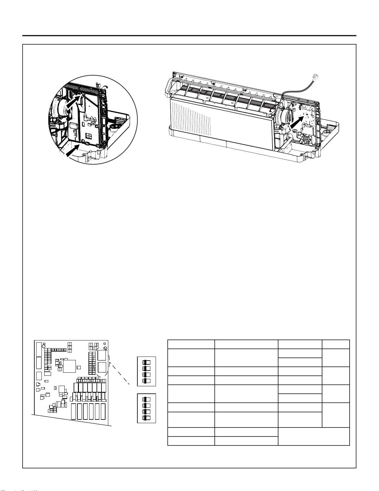
Installation of the UVC Main Board
1. Disconnect the thermistor wire harness from the main board.
2. Remove the two screws at the top and bottom of the white main board cover using a 1/4” driver and save.
3. Remove the main board cover and set aside.
4. Disconnect the indoor fan motor connector.
5. Detach all electrical connectors from the front of the main board.
7KHPDLQERDUGLVVHFXUHGE\DZKLWHUHWDLQLQJSLQ6TXHH]HWKHFRQQHFWRUSURQJVXQWLOLWVOLGHVEDFNDQGUHOHDVHV
the main board.
7. Discharge possible stored energy from the capacitor using high voltage discharge pliers.
8. Unplug remaining connectors on the main board taking note of the connector locations. Connectors are color coded.
5HPRYHDQGGLVFDUGWKHPDLQERDUGIURPWKHFKDVVLV7KLVPDLQERDUGZLOOQRORQJHUEHXVHG
%HIRUHLQVWDOOLQJWKHQHZ89&PDLQERDUGUHIHUWRWKHPLQLPDQXDOIRULQVWUXFWLRQVRQKRZWRFRQ¿JXUHWKHVHWWLQJV
IRU\RXUVSHFL¿FPRGHO
11. Remove the new UVC main board from the kit packaging.
12. Reinstall terminals on the new UVC main board making sure black and brown wires are on their correct terminals.
1/4” screws White retaining pin
S2
S3
2341
ON CIT
2341
ON CIT
Service Board Set-Up
Switch Position Meaning Switch Setting Meaning
S2-1 OFF=heat pump
ON=air conditioner
6 Rႇ N%78
6 Rႇ
S2-2 %786HWWLQJV S2-2=on N%78
S2-3 %786HWWLQJV 6 Rႇ
S2-4 Make-up air module
¿WWHG
6 Rႇ N%78
S2-3=on
S3-1 +HDWSLSHRSWLRQ¿WWHG S2-2=on N%78
S3-2 OFF = 230/208V model
ON = 265V model
S2-3=on
S3-3 Not used
S3-4 Not used
Loading ...
Loading ...
Loading ...