Loading ...
Loading ...
Loading ...
37
ENGLISH
CAUTION
• Request the function settings to the installation specialist during
the outside unit installation.
• When the function is not used, set it to OFF.
• If the temperature of the outside unit installation place is 0°C or
less, we recommend the connection and usage of Sump Heater.
!
Use Sump Heater
It is the function to select when you want to connect and use Sump
Heater.
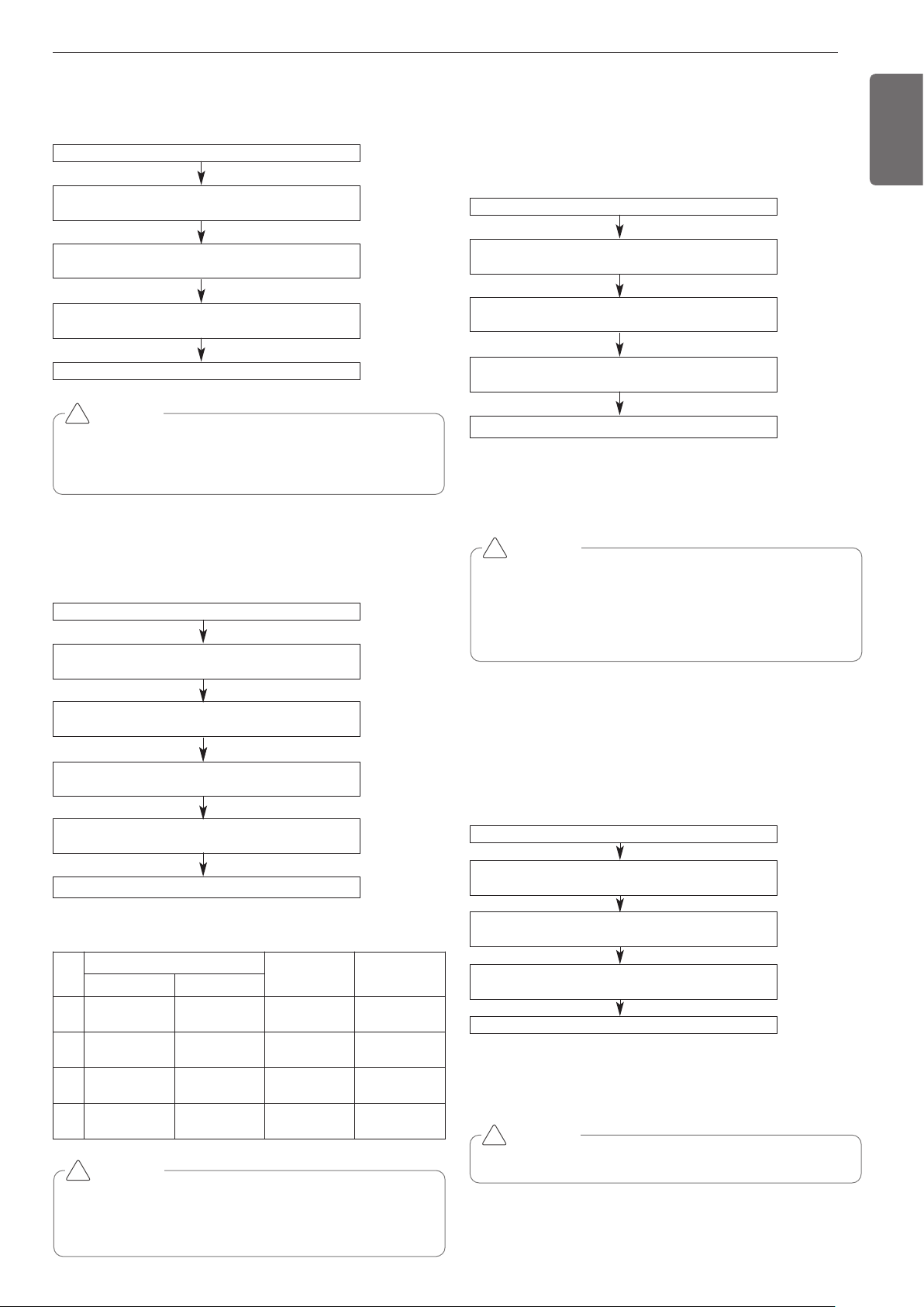
How to set the mode
Mode setting
- ON: Set to control the Sump Heater from the product
- OFF: Set not to control the Sump Heater from the product
Mode setting
- ON: Set to control the Low capacity mode
- OFF: Set not to control
Turn on DIP switch No.5 of the master unit PCB
Use ‘▶‘ and ‘◀‘ button to mark “Func” in the 7 seg-
ment, and press ‘●‘ button.
Use ‘▶‘ and ‘◀‘ button to mark “Fn8” in the 7 seg-
ment, and press ‘●‘ button.
Use ‘▶‘ and ‘◀‘ button to select between “ON” and
“OFF” in the 7 segment, and press ‘●‘ button.
Decide Sump Heater control according to the set mode.
IDU capacity adjusting
If the operation of indoor unit is more than 130%, the air flow is oper-
ated as low in the all indoor units.
How to set the mode
Turn on DIP switch No.5 of the master unit PCB
Use ‘▶‘ and ‘◀‘ button to mark “Func” in the 7 seg-
ment, and press ‘●‘ button.
Use ‘▶‘ and ‘◀‘ button to mark “Fn9” in the 7 seg-
ment, and press ‘●‘ button.
Use ‘▶‘ and ‘◀‘ button to select between “ON” and
“OFF” in the 7 segment, and press ‘●‘ button.
CAUTION
• Ask an authorized technician to setting a function.
!
IDU capacity adjusting mode is set
Setting the outside unit address
How to set the mode
Turn on DIP switch No.5 of the master unit PCB
Use ‘▶‘ and ‘◀‘ button to mark “Func” in the 7 seg-
ment, and press ‘●‘ button.
Use ‘▶‘ and ‘◀‘ button to mark “Fn5” in the 7 seg-
ment, and press ‘●‘ button.
Use ‘▶‘ and ‘◀‘ button to select one among “0” ~
“254” in the 7 segment, and press ‘●‘ button.
Outside unit address is set.
CAUTION
• Request the function settings to the installation specialist during
the outside unit installation.
• If use a function, first install a Central controller.
!
Target pressure adjusting
How to set the mode
Turn on DIP switch No.5 of the master unit PCB
Use ‘▶‘ and ‘◀‘ button to mark “Func” in the 7 seg-
ment, and press ‘●‘ button.
Use ‘▶‘ and ‘◀‘ button to mark “Fn7” in the 7 seg-
ment, and press ‘●‘ button.
Select the Option using ‘▶’, ‘◀’ Button :
“op1” ~ “op4” Push the ‘●’ button
Decide target pressure according to the set mode.
Select the Option using ‘▶’, ‘◀’ Button :
“HEAT” , “COOL” Push the ‘●’ button
CAUTION
• Ask an authorized technician to setting a function.
• If do not use a function, set an off-mode.
• Change a power consumption or capacity.
!
Setting
mod
e
Purpose
Condensing
temperature
variation
Evaporating
temperature
variation
“Heat” “Cool”
op1
Increase
capacity
Increase
capacity
-3°C(26.6°F) +2°C(35.6°F)
op2
Decrease power
consumption
Increase
capacity
-1.5°C(29.3°F) -2°C(28.4°F)
op3
Decrease power
consumption
Decrease power
consumption
+2.5°C(36.5°F) -4°C(24.8°F)
op4
Decrease power
consumption
Decrease power
consumption
+4.5°C(40.1°F) -6°C(21.2°F)
Loading ...
Loading ...
Loading ...