Loading ...
Loading ...
Loading ...
10
ENGLISH
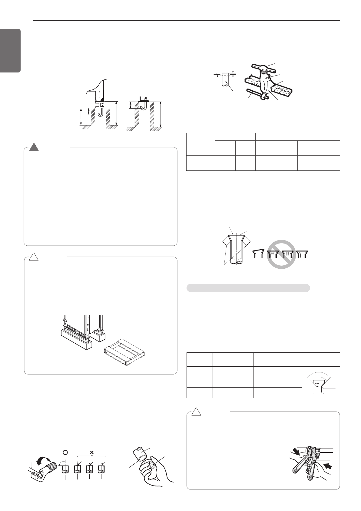
Unit: mm(inch)
200(7-7/8)
75(2-61/64)
75(2-61/64)
200(7-7/8)
100(3-15/16)
Ⓐ The corner part must be fixed firmly. Otherwise, the support for the
installation may be bent.
Ⓑ Get and use M10 Anchor bolt.
Ⓒ Put Cushion Pad between the outside unit and ground support for
the vibration protection in wide area.
Ⓓ Space for pipes and wiring (Pipes and wirings for bottom side)
Ⓔ H-beam support
Ⓕ Concrete support
CAUTION
• Be sure to remove the Pallet(Wood Support) of the bottom
side of the outside unit Base Pan before fixing the bolt. It
may cause the unstable state of the outdoor settlement,
and may cause freezing of the heat exchanger resulting in
abnormal operations.
• Be sure to remove the Pallet(Wood Support) of the bottom
side of the outside unit before welding. Not removing Pal-
let(Wood Support) causes hazard of fire during welding.
WARNING
• Install where it can sufficiently support the weight of the out-
side unit .
If the support strength is not enough, the outside unit may
drop and hurt people.
• Install where the outside unit may not fall in strong wind or
earthquake.
If there is a fault in the supporting conditions, the outside unit
may fall and hurt people.
• Please take extra cautions on the supporting strength of the
ground, water outlet treatment(treatment of the water flowing
out of the outside unit in operation), and the passages of the
pipe and wiring, when making the ground support.
• Do not use tube or pipe for water outlet in the Base pan. Use
drainage instead for water outlet. The tube or pipe may freeze
and the water may not be drained.
Pallet(Wood Support)
- Remove before Installation
!
!
Main cause of gas leakage is defect in flaring work. Carry out correct
flaring work in the following procedure.
Cut the pipes and the cable
- Use the accessory piping kit or the pipes purchased locally.
- Measure the distance between the indoor and the outside unit .
- Cut the pipes a little longer than measured distance.
- Cut the cable 1.5m(4.92ft) longer than the pipe length.
Pipe
Reamer
Point down
Copper
tube
90
Slanted Uneven Rough
Preparation of Piping
Burrs removal
- Completely remove all burrs from the cut cross section of pipe/tube.
- Put the end of the copper tube/pipe to downward direction as you re-
move burrs in order to avoid to let burrs drop in the tubing.
Flaring work
- Carry out flaring work using flaring tool as shown below.
Firmly hold copper tube in a bar(or die) as indicated dimension in the
table above.
Check
- Compare the flared work with figure below.
- If flare is noted to be defective, cut off the flared section and do flar-
ing work again.
Bar
Copper pipe
Clamp handle
Red arrow mark
Cone
Yoke
Handle
Bar
"A"
Inclined
Inside is shining without scratches.
Smooth all round
Even length
all round
Surface
damaged
Cracked Uneven
thickness
= Improper flaring =
Flare shape and flare nut tightening torque
Precautions when connecting pipes
- See the following table for flare part machining dimensions.
- When connecting the flare nuts, apply refrigerant oil to the inside and
outside of the flares and turn them three or four times at first. (Use
ester oil or ether oil.)
-
See the following table for tightening torque.(Applying too much torque may
cause the flares to crack.)
- After all the piping has been connected, use nitrogen to perform a
gas leak check.
CAUTION
• Always use a charge hose for service port connection.
•
After tightening the cap, check that no refrigerant leaks are present
.
• When loosening a flare nut, always use two wrenches in
combination, When connecting the piping,
always use a spanner and torque wrench
in combination to tighten the flare nut.
• When connecting a flare nut, coat the
flare(inner and outer faces) with oil for
R410A(PVE) and hand tighten the nut
3 to 4 turns as the initial tightening.
Union
!
Indoor unit
[kW(Btu/h)]
Pipe [mm(inch)] "A" [mm(inch)]
Gas Liquid Gas Liquid
<5.6 (19,100) 12.7(1/2) 6.35(1/4) 0.5~0.8 (0.02~0.03) 0~0.5 (0~0.02)
<16.0 (54,600) 15.88(5/8) 9.52(3/8) 0.8~1.0 (0.03~0.04) 0.5~0.8 (0.02~0.03)
<22.4 (76,400) 19.05(3/4) 9.52(3/8) 1.0~1.3 (0.04~0.05) 0.5~0.8 (0.02~0.03)
pipe size
[mm(inch)]
Tightening Torque
N·m(lbs ·ft)
A [mm(inch)] Flare shape
Ø9.52(3/8) 38±4(28±3.0) 12.8(0.5)~13.2(0.52)
90
2
45
2
A
R=0.4~0.8
Ø12.7(1/2) 55±6(41±4.4) 16.2(0.64)~16.6(0.65)
Ø15.88(5/8) 75±7(55±5.2) 19.3(0.76)~19.7(0.78
Loading ...
Loading ...
Loading ...