Loading ...
Loading ...
Loading ...
23
ENGLISH
NOTE
!
If the ambient temperature differs between the time when pressure is applied
and when the pressure drop is checked, apply the following correction factor
There is a pressure change of approximately 0.01Mpa(1.5psi) for each 33.8°F
of temperature difference.
Correction= (Temp. at the time of pressurization – Temp. at the time of check)
X 0.1
For example: Temperature at the time of pressurization
3.8MPa(551psi) is 80.6°F
24 hour later: 3.73MPa(541psi), 68°F
In this case the pressure drop of 0.07MPa(10psi) is
because of temperature drop
And hence there is no leakage in pipe occurred.
CAUTION
To prevent the nitrogen from entering the refrigeration system in
the liquid state, the top of the cylinder must be at higher position
than the bottom when you pressurize the system.
Usually the cylinder is used in a vertical standing position.
!
WARNING
Use a vacuum pump or Inert(nitrogen) gas when doing leakage
test or air purge. Do not compress air or Oxygen and do not use
Flammable gases. Otherwise, it may cause fire or explosion.
- There is the risk of death, injury, fire or explosion.
!
Vacuum
Vacuum drying should be made from the service port provided on the outdoor
unit’s service valve to the vacuum pump commonly used for liquid pipe, gas pipe
and high/low pressure common pipe. (Make Vacuum from liquid pipe, gas pipe and
high/low pressure common pipe with the service valve closed.)
* Never perform air purging using refrigerant.
• Vacuum drying: Use a vacuum pump that can evacuate to -100.7kPa (-
14.6psi, 5 Torr, -755mmHg).
- Evacuate the system from the liquid and gas pipes with a vacuum pump
for over 2 hrs and bring the system to -100.7kPa(-14.6psi). After maintain-
ing system under that condition for over 1 hr, confirm the vacuum gauge
rises. The system may contain moisture or leak.
- Following should be executed if there is a possibility of moisture remain-
ing inside the pipe.
(Rainwater may enter the pipe during work in the rainy season or over a
long period of time)
After evacuating the system for 2 hrs, give pressure to the system to
0.05MPa(7.3psi) (vacuum break) with nitrogen gas and then evacuate it
again with the vacuum pump for 1hr to -100.7kPa(-14.6psi)(vacuum dry-
ing). If the system cannot be evacuated to -100.7kPa(-14.6psi) within 2
hrs, repeat the steps of vacuum break and its drying. Finally, check if the
vacuum gauge does not rise or not, after maintaining the system in vac-
uum for 1 hr.
Indoor unit
Liquid side
Gas side
High Pressure
Gas pipe
High Pressure
Gas pipe
Liquide pipe
Liquide pipe
Low Pressure
Gas pipe
Low Pressure
Gas pipe
HR unit
Scale
Use a graviometer. (One that can
measure down to 0.1kg). If you are
unable to prepare such a
high-precision gravimeter you may use
a charge cylinder.
Slave 1 outside unit Master outside unit
Close
Close
Close
Vacuum
pump
Vacuum
pump
Close
Close
Close
NOTE
!
Always add an appropriate amount of refrigerant. (For the refrigerant addi-
tional charge)
Too much or too little refrigerant will cause trouble.
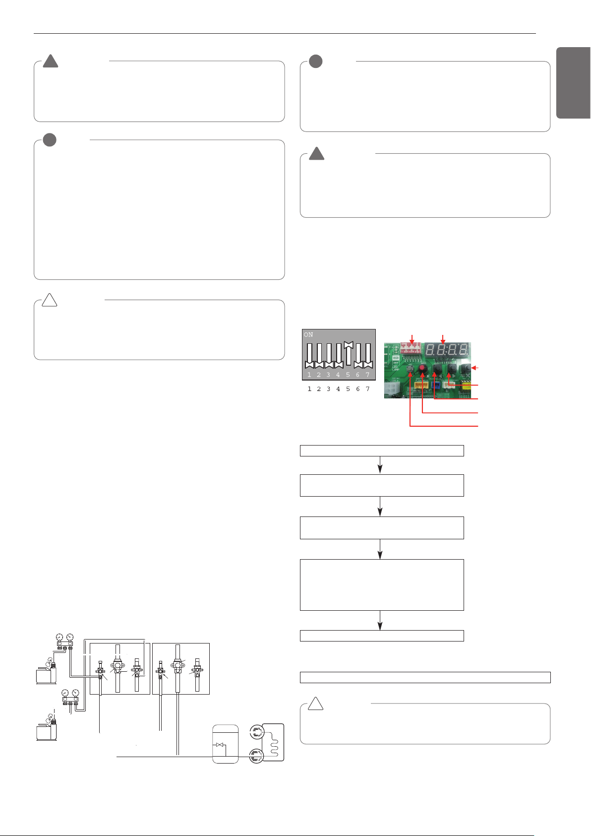
To use the Vacuum Mode
(If the Vacuum mode is set, all valves of Indoor units and Outdoor units will
be opened.)
WARNING
When installing and moving the air conditioner to another site,
recharge after perfect evacuation.
- If a different refrigerant or air is mixed with the original refriger-
ant, the refrigerant cycle may malfunction and the unit may be
damaged.
!
This function is used for creating vacuum in the system after compres-
sor replacement, ODU parts replacement or IDU addition/replacement.
Vacuum mode setting method
Vacuum mode off method
CAUTION
ODU operation stops during vacuum mode. Compressor can't
operate.
Master unit PCB DIP switch on : No.5
Vacuum mode
Select the mode using ‘▶’, ‘◀’ Button :
“SVC” Push the ‘●’ button
Select the Function using ‘▶’, ‘◀’ Button :
“Se1” Push the ‘●’ button
Start the vacuum mode : “VACC”
ODU V/V open
ODU EEV open
IDU EEV open
Dip switch off and push the reset button on Master unit PCB
!
Vacuum Mode
DIP SWITCH 7-Segment
SW01C ( : confirm)
SW02C ( : backward
: forward)
SW04C
( X : cancel)
SW01D (reset)
SW03C (
ȭ
ȯ
Ɨ
Loading ...
Loading ...
Loading ...