Loading ...
Loading ...
Loading ...
Automatic Addressing
The address of indoor units would be set by Automatic Addressing
- Wait for 3 minutes after supplying power.
(Master and Slave outside unit s, indoor units)
- Press RED button of the outside unit s for 5 seconds. (SW01C)
- A “88” is indicated on 7-segment LED of the outside unit PCB.
- For completing addressing, 2~7 minutes are required depending on
numbers of connected indoor units
-
Numbers of connected indoor units whose addressing is completed are
indicated for 30 seconds on 7-segment LED of the outside unit PCB
- Numbers of connected HR units whose addressing is completed are in-
dicated for 10 seconds on 7-segment LED of the outside unit PCB
- After completing addressing, address of each indoor unit is indicated
on the wired remote control display window. (CH01, CH02,
CH03, ……, CH06 : Indicated as numbers of connected indoor units)
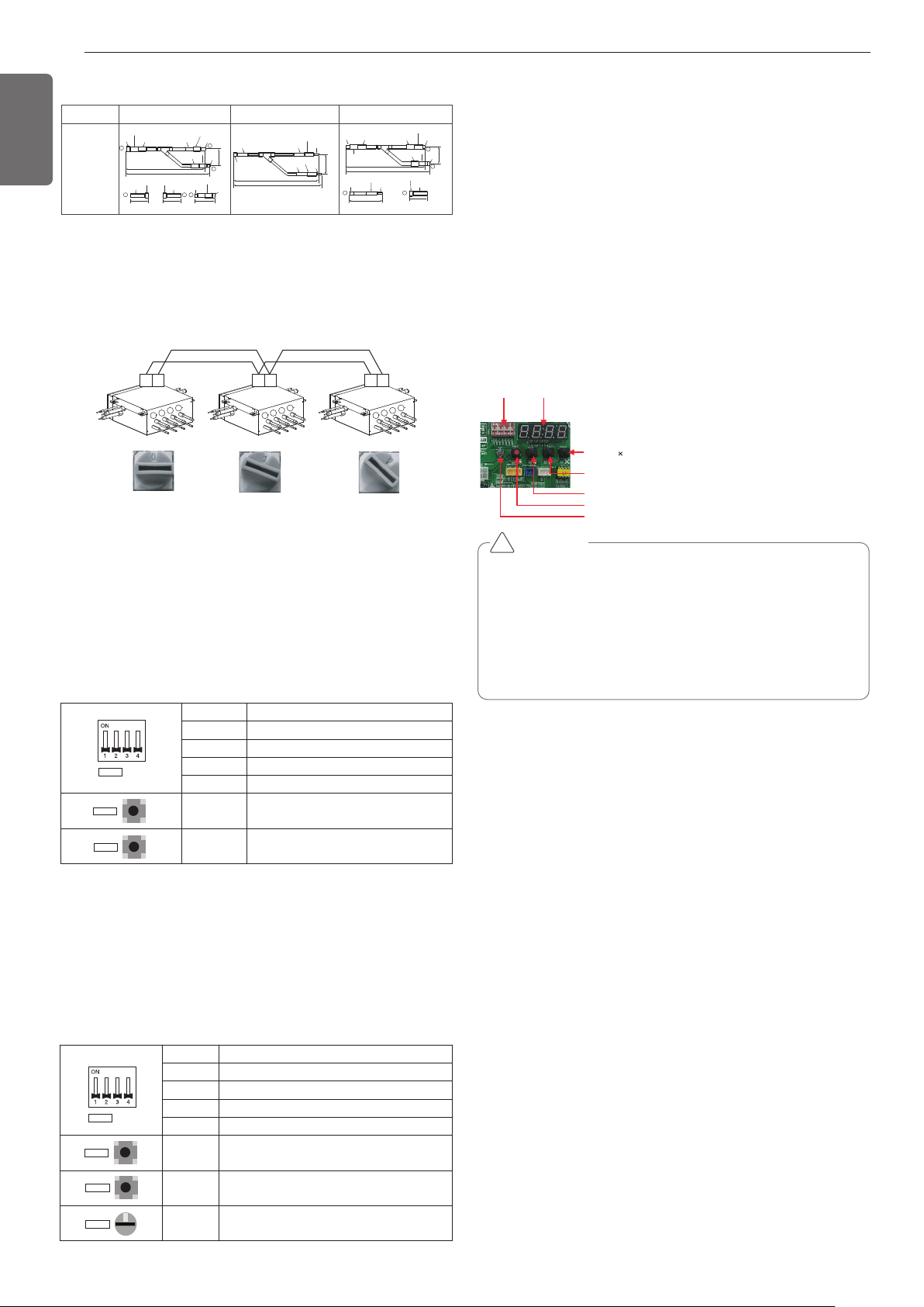
[MAIN PCB]
DIP-SWITCH 7 - Segment
SW01C ( : confirm)
SW02C (ඔ : backward)
SW03C (ඖ : forward)
SW04C (
: cancel)
SW01D (reset)
CAUTION
• In replacement of the indoor unit PCB, always perform Automatic
addressing setting again (At that time, please check about using
Independent power module to any indoor unit.)
• If power supply is not applied to the indoor unit, operation error
occur.
• Automatic Addressing is only possible on the master Unit.
• Automatic Addressing has to be performed after 3 minutes to im-
prove communication.
!
Automatic pipe detection
1. Turn No.1 of SW02M of HR unit PCB off.
2. Confirm that the setting of No.2, 3 of SW02M corresponds with the
number of indoor units.
3. Reset the power of HR unit PCB
4. Master unit PCB DIP switch on : No.5
5. Select the mode using ‘▶’, ‘◀’ Button : “Idu” Push the ‘●’ button
6. Select the “Id 5” function using ‘▶’, ‘◀’ Button :“Ath” or “”Atc”
Push the ‘●’ button.
Outdoor temperature is over 15°C(59°F) : “Atc” Using (If it fail, use
“Ath”)
Outdoor temperature is below 15°C(59°F) : “Ath” Using (If it fail,
use “Atc”)
7. Select the mode using ‘▶’, ‘◀’ Button : “Idu” Push the ‘●’ button
8. Select the “Id 6” function using ‘▶’, ‘◀’ Button :“StA” Push the
‘●’ button
9. Operated after 88 is displayed on 7-SEG of the outside unit main
PCB.
10. Pipe detection proceed.
11. 5~30 minutes are required depending on the number of the indoor
units and outdoor temperature.
12. The number of the indoor units installed is displayed on 7-SEG of
the outside unit main PCB for about 1 minute
- For a HR unit, the number of the indoor units connected to each
HR unit is displayed.
- '200' is displayed in case of auto pipe detection error, and auto de-
tection is completed after '88' is disappeared.
* Auto pipe detection function : the function that sets connection re-
lationship automatically between the indoor unit and HR unit.
32
ENGLISH
ARBLB03321
Models
413(16-1/4)
390(15-11/32)
I.D19.05(3/4)
I.D19.05(3/4)
I.D19.05(3/4)
I.D15.88(5/8)
I.D12.7(1/2)
I.D12.7(1/2)
I.D12.7(1/2)
I.D12.7(1/2)
I.D12.7(1/2)
I.D12.7(1/2)
I.D12.7
(1/2)
74
(2-29/32)
70(2-3/4)
70(2-3/4)
I.D15.88(5/8)
I.D15.88(5/8)
I.D25.4(1)
I.D25.4(1)
I.D25.4(1)
O.D25.4(1)
80(3-5/32)
110(4-11/32) 110(4-11/32)
332(13-1/16)
321(12-5/8)
83
(3-9/32)
1
2
3
3
I.D19.05(3/4)
I.D19.05(3/4)
O.D19.05(3/4)
O.D19.05(3/4)
2
3 2
3
1 2
O.D15.88(5/8)
444(17-15/32)
421(16-9/16)
96
(3-25/32)
I.D15.88
(5/8)
I.D22.2(7/8)
I.D22.2(7/8)
I.D22.2(7/8)
I.D22.2(7/8)
I.D22.2(7/8)
I.D22.2(7/8)
O.D15.88(5/8)
I.D6.35(1/4)
I.D6.35(1/4)
I.D28.58(1-1/8)
I.D19.05(3/4)
I.D9.52(3/8)
I.D9.52(3/8)
I.D9.52(3/8)
I.D9.52(3/8)
Low Pressure Gas Pipe High Pressure Gas PipeLiquid pipe
Y branch pipe
[Unit : mm(inch)]
SW05M (Rotary S/W for addressing HR unit)
Must be set to '0' when installing only one HR unit.
When installing multiple HR units, address the HR units with sequen-
tially increasing numbers starting from '0'.
Ex) Installation of 3 HR units
1
2
3
4
1
2
3
4
1
2
3
4
AB AB AB
S/W No. Setup
No.1 Manual addressing of valve #1
No.2 Manual addressing of valve #2
No.3 Manual addressing of valve #3
No.4 Manual addressing of valve #4
SW03M
Increase in the digit of 10 of valve
address
SW04M
Increase in the last digit of valve ad-
dress
SW01M
SW03M
SW04M
2. Zoning setting
- Set the address of the valve of the HR unit to the central control
address of the connected indoor unit.
- SW01M : selection of the valve to address
SW03M : increase in the digit of 10 of valve address
SW04M : increase in the last digit of valve address
SW05M :Rotary S/W
- Prerequisite for manual valve addressing : central control address
of each indoor unit must be preset
differently at its wired remote control.
S/W No. Setup
No.1 Manual addressing of valve #1
No.2 Manual addressing of valve #2
No.3 Manual addressing of valve #3
No.4 Manual addressing of valve #4
SW03M
Increase in the digit of 10 of valve ad-
dress
SW04M Increase in the last digit of valve address
SW05M Manual addressing of zoning indoor units
SW01M
SW03M
SW04M
SW05M
0
SW01M/SW03M/SW04M (Dip S/W and tact S/W for
manual valve addressing)
1. Normal setting (Non-Zoning setting)
- Set the address of the valve of the HR unit to the central control
address of the connected indoor unit.
- SW01M: selection of the valve to address
SW03M: increase in the digit of 10 of valve address
SW04M: increase in the last digit of valve address
- Prerequisite for manual valve addressing : central control address
of each indoor unit must be preset differently at its wired remote
control.
Loading ...
Loading ...
Loading ...