Home
Bookmarks
Home
Binder
Binder MKF 720 User Manual
Page 169
Binder MKF 720 Dynamic climate chamber with humidity control, -liter capacity
User Manual - Page 169
For MKF 720.
PDF File Manual
,
177 pages
,
Read Online
|
Download pdf file
More photos
1. Safety
1.1 Personnel Qualification
1.2 Operating manual
1.3 Legal considerations
1.4 Structure of the safety instructions
1.4.1 Signal word panel
1.4.2 Safety alert symbol
1.4.3 Pictograms
1.4.4 Word message panel structure
1.5 Localization / position of safety labels on the chamber
1.6 Type plate
1.7 General safety instructions on installing and operating the chamber
1.8 Intended use
1.9 Foreseeable Misuse
1.10 Residual Risks
1.11 Operating instructions
1.12 Measures to prevent accidents
1.13 Resistance of the humidity sensor against harmful substances
2. Chamber description
2.1 Chamber overview
2.2 Instrument panel
2.3 Lateral control panel
2.4 Main power switch (MKF 56)
2.5 Rear power switch (MKF / MKFT 115, 240, 720)
2.6 Rear chamber view
3. Completeness of delivery, transportation, storage, and installation
3.1 Unpacking, and checking equipment and completeness of delivery
3.2 Guidelines for safe lifting and transportation
3.3 Storage
3.4 Location of installation and ambient conditions
4. Installation and connections
4.1 Wastewater connection for humidifying system
4.2 Freshwater supply for humidifying system
4.2.1 Automatic fresh water supply for humidifying system via water pipe
4.2.2 Manual fresh water supply via external freshwater can (option for MKF 56)
4.2.3 Manual fresh water supply for humidifying system via internal freshwater can (MKF/MKFT 115, 240, 720)
4.2.4 Water circle: lever for condensate recycling (option for MKF/MKFT 115, 240, 720)
4.3 Connection of cooling water outlet for water cooling (option for MKFT 720 and MKF)
4.4 Connection of cooling water inlet for water cooling (option for MKFT 720 and MKF)
4.5 Connection kit for connecting the chamberâs freshwater connection to a water pipe
4.6 Safety kit: Hose burst protection device with reflux protection device for the chamberâs freshwater connection (available via BINDER INDIVIDUAL customized solutions)
4.7 Installation of the voltage and frequency changer(chambers with voltage and frequency changer)
4.8 Electrical connection
4.8.1 Information on connecting the alternating climate chamber
4.8.2 Connecting the voltage and frequency changer (for chambers equipped with a voltage and frequency changer)
5. Functional overview of the MB2 chamber controller
5.1 Operating functions in normal display
5.2 Display views: Normal display, program display, chart-recorder display
5.3 Controller icons overview
5.4 Operating modes
5.5 Controller menu structure
5.5.1 Main menu
5.5.2 âSettingsâ submenu
5.5.3 âServiceâ submenu
5.6 Principle of controller entries
5.7 Performance during and after power failures
5.8 Performance when opening the door
6. Start up
6.1 Turning on the chamber
6.2 Controller settings upon start up
6.3 Turning on/off humidity control
7. Set-point entry in âFixed valueâ operating mode
7.1 Set-point entry through the âSetpointsâ menu
7.2 Direct setpoint entry via Normal display
7.3 Special controller functions via operation lines
8. Timer program: stopwatch function
8.1 Starting a timer program
8.1.1 Performance during program delay time
8.2 Stopping a running timer program
8.2.1 Pausing a running timer program
8.2.2 Cancelling a running timer program
8.3 Performance after the end of the program
9. Time programs
9.1 Starting an existing time program
9.1.1 Performance during program delay time
9.2 Stopping a running time program
9.2.1 Pausing a running time program
9.2.2 Cancelling a running time program
9.3 Performance after the end of the program
9.4 Creating a new time program
9.5 Program editor: program management
9.5.1 Deleting a time program
9.6 Section editor: section management
9.6.1 Add a new program section
9.6.2 Copy and insert or replace a program section
9.6.3 Deleting a program section
9.7 Value entry for a program section
9.7.1 Section duration
9.7.2 Set-point ramp and set-point step
9.7.3 Special controller functions via operation lines
9.7.4 Setpoint entry
9.7.5 Tolerance range
9.7.6 Repeating one or several sections within a time program
9.7.7 Saving the time program
10. Week programs
10.1 Starting an existing week program
10.2 Cancelling a running week program
10.3 Creating a new week program
10.4 Program editor: program management
10.4.1 Deleting a week program
10.5 Section editor: section management
10.5.1 Add a new program section
10.5.2 Copy and insert or replace a program section
10.5.3 Deleting a program section
10.6 Value entry for a program section
10.6.1 Set-point ramp and set-point step modes
10.6.2 Weekday
10.6.3 Start time
10.6.4 Setpoint entry
10.6.5 Special controller functions via operation lines
11. Notification and alarm functions
11.1 Notification and alarm messages overview
11.1.1 Notifications
11.1.2 Alarm messages
11.1.3 Messages concerning the humidity system
11.2 State of alarm
11.3 Resetting an alarm, list of active alarms
11.4 Activating / deactivating the audible alarm (alarm buzzer)
12. Temperature safety devices
12.1 Over temperature protective device (class 1)
12.2 Safety controller (over temperature safety device class 2)
12.2.1 Safety controller modes
12.2.2 Setting the safety controller
12.2.3 Message and measures in the state of alarm
12.2.4 Function check
12.3 Over/under temperature safety device class 2 (option)
13. User management
13.1 Authorization levels and password protection
13.2 Log in
13.3 Log out
13.4 User change
13.5 Password assignment and password change
13.5.1 Password change
13.5.2 Deleting the password for an individual authorization level
13.5.3 New password assignment for âserviceâ or âadminâ authorization level when the password function was deactivated
13.6 Activation code
14. General controller settings
14.1 Selecting the controllerâs menu language
14.2 Setting date and time
14.3 Selecting the temperature unit
14.4 Display configuration
14.4.1 Adapting the display parameters
14.4.2 Touchscreen calibration
14.5 Network and communication
14.5.1 Serial interfaces
14.5.2 Ethernet
14.5.2.1 Configuration
14.5.2.2 Display of MAC address
14.5.3 Web server
14.5.4 E-Mail
14.6 USB menu: Data transfer via USB interface
14.7 Turning off the interior lighting automatically
15. General information
15.1 Service contact page
15.2 Current operating parameters
15.3 Event list
15.4 Technical chamber information
15.5 Self-test function (MK 56)
16. Chart recorder display
16.1 Views
16.1.1 Show and hide legend
16.1.2 Switch between legend pages
16.1.3 Show and hide specific indications
16.1.4 History display
16.2 Setting the parameters
17. Humidification / dehumidification system
17.1 Function of the humidifying and dehumidifying system
17.1.1 Freshwater
17.1.1.1 Automatic freshwater supply via water pipe
17.1.1.2 Manual fresh water supply via external freshwater can (option for MKF 56)
17.1.1.3 Manual fresh water supply via internal freshwater can (MKF/MKFT 115, 240, 720)
17.1.2 Wastewater
18. Defrosting at refrigerating operation
19. Anti-condensation protection via operation line
20. Zero-voltage switching outputs via operation lines
21. Options
21.1 APT-COM⢠4 Multi Management Software (option)
21.2 RS485 interface (option)
21.3 Data logger kits (option)
21.4 Analog outputs for temperature and humidity (option)
21.5 Compressed air connection (option)
21.6 Controlled compressed air dryer (option)
21.7 Water cooling (option for MKF 56, 115, 240, 720, and MKFT 720)
21.8 Object temperature display with flexible Pt 100 temperature sensor (option)
21.9 External freshwater and wastewater cans (option for MKF 56)
21.9.1 Connecting the freshwater can and the pump
21.9.2 Connecting the wastewater can
21.9.3 Connecting with wastewater recycling
21.10 BINDER Pure Aqua Service (option)
22. Cleaning and decontamination
22.1 Cleaning
22.2 Decontamination / chemical disinfection
23. Maintenance and service, troubleshooting, repair, testing
23.1 General information, personnel qualification
23.2 Maintenance intervals, service
23.3 Simple troubleshooting
23.4 Sending the chamber back to BINDER GmbH
24. Disposal
24.1 Disposal of the transport packing
24.2 Decommissioning
24.3 Disposal of the chamber in the Federal Republic of Germany
24.4 Disposal of the chamber in the member states of the EU except for the Federal Republic of Germany
24.5 Disposal of the chamber in non-member states of the EU
25. Technical description
25.1 Factory calibration and adjustment
25.2 Over current protection
25.3 Definition of usable volume
25.4 MKF (E5) technical data
25.5 MKFT (E5) technical data
25.6 Equipment and options (extract)
25.7 Accessories and spare parts (extract)
25.8 MKF heating-up and cooling-down graphs
25.9 MKFT heating-up and cooling-down graphs
25.10 MKF heat compensation graphs
25.11 MKFT heat compensation graphs
25.12 Dimensions
26. Certificates and declarations of conformity
26.1 EU Declaration of Conformity for MKF
26.2 EU Declaration of Conformity for MKFT
26.3 Certificate for the GS mark of conformity of the âDeutsche Gesetzliche Unfallversicherung e.V.â (German Social Accident Insurance) DGUV
27. Product registration
27.1 Registering a BINDER chamber
27.2 Multi Management Software APT-COM⢠4 BASIC-Edition
28. Contamination clearance certificate
28.1 For chambers located outside the USA and Canada
28.2 For chambers located in the USA and Canada
Leere Seite
Page 169/177
Page 1
Page 2
Page 3
Page 4
Page 5
Page 6
Page 7
Page 8
Page 9
Page 10
Page 11
Page 12
Page 13
Page 14
Page 15
Page 16
Page 17
Page 18
Page 19
Page 20
Page 21
Page 22
Page 23
Page 24
Page 25
Page 26
Page 27
Page 28
Page 29
Page 30
Page 31
Page 32
Page 33
Page 34
Page 35
Page 36
Page 37
Page 38
Page 39
Page 40
Page 41
Page 42
Page 43
Page 44
Page 45
Page 46
Page 47
Page 48
Page 49
Page 50
Page 51
Page 52
Page 53
Page 54
Page 55
Page 56
Page 57
Page 58
Page 59
Page 60
Page 61
Page 62
Page 63
Page 64
Page 65
Page 66
Page 67
Page 68
Page 69
Page 70
Page 71
Page 72
Page 73
Page 74
Page 75
Page 76
Page 77
Page 78
Page 79
Page 80
Page 81
Page 82
Page 83
Page 84
Page 85
Page 86
Page 87
Page 88
Page 89
Page 90
Page 91
Page 92
Page 93
Page 94
Page 95
Page 96
Page 97
Page 98
Page 99
Page 100
Page 101
Page 102
Page 103
Page 104
Page 105
Page 106
Page 107
Page 108
Page 109
Page 110
Page 111
Page 112
Page 113
Page 114
Page 115
Page 116
Page 117
Page 118
Page 119
Page 120
Page 121
Page 122
Page 123
Page 124
Page 125
Page 126
Page 127
Page 128
Page 129
Page 130
Page 131
Page 132
Page 133
Page 134
Page 135
Page 136
Page 137
Page 138
Page 139
Page 140
Page 141
Page 142
Page 143
Page 144
Page 145
Page 146
Page 147
Page 148
Page 149
Page 150
Page 151
Page 152
Page 153
Page 154
Page 155
Page 156
Page 157
Page 158
Page 159
Page 160
Page 161
Page 162
Page 163
Page 164
Page 165
Page 166
Page 167
Page 168
Page 169
Page 170
Page 171
Page 172
Page 173
Page 174
Page 175
Page 176
Page 177
Contents
Table of Contents
Search
Previous
Next
Troubleshooting
Bookmarks
Loading ...
Loading ...
Loading ...
MKF / M
KFT
(E
5
)
06/2
020
page 169
/
17
6
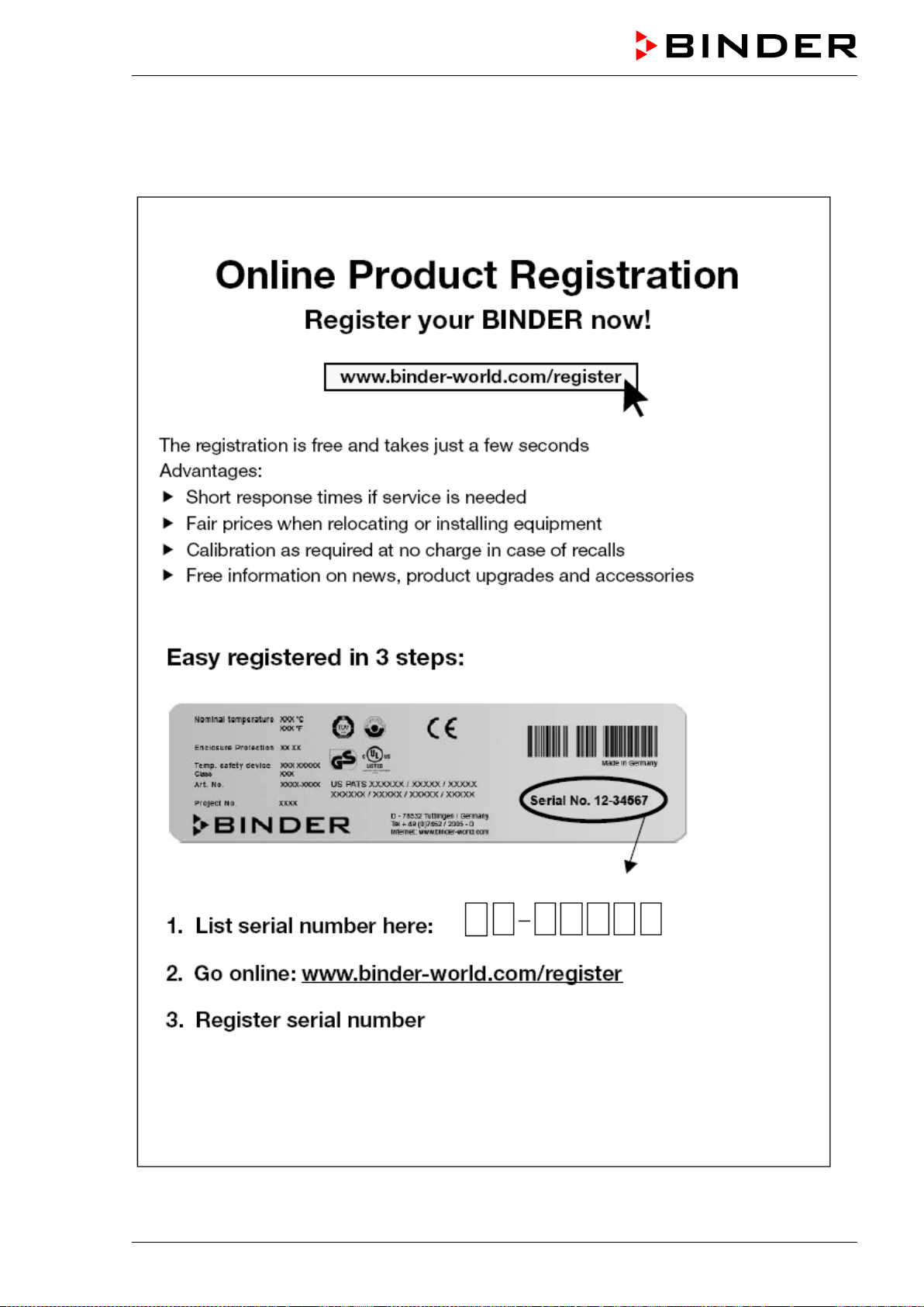
27.
Product
registration
27.1
Register
ing a BIN
DER chamb
er
Loading ...
Loading ...
Loading ...
File type: PDF
File name: 70531206_mkf-56.pdf
File size: 11.28 MB
File Language: English
Pages: 177
Author: Binder
File created: 2020-06-19
Published:
2021-08-19
Updated: 2023-05-22
Download File
Table of Contents
×
1. Safety
7
1.1 Personnel Qualification
7
1.2 Operating manual
7
1.3 Legal considerations
7
1.4 Structure of the safety instructions
8
1.4.1 Signal word panel
8
1.4.2 Safety alert symbol
8
1.4.3 Pictograms
9
1.4.4 Word message panel structure
9
1.5 Localization / position of safety labels on the chamber
10
1.6 Type plate
12
1.7 General safety instructions on installing and operating the chamber
13
1.8 Intended use
14
1.9 Foreseeable Misuse
16
1.10 Residual Risks
17
1.11 Operating instructions
18
1.12 Measures to prevent accidents
18
1.13 Resistance of the humidity sensor against harmful substances
19
2. Chamber description
20
2.1 Chamber overview
21
2.2 Instrument panel
21
2.3 Lateral control panel
22
2.4 Main power switch (MKF 56)
23
2.5 Rear power switch (MKF / MKFT 115, 240, 720)
23
2.6 Rear chamber view
24
3. Completeness of delivery, transportation, storage, and installation
26
3.1 Unpacking, and checking equipment and completeness of delivery
26
3.2 Guidelines for safe lifting and transportation
27
3.3 Storage
27
3.4 Location of installation and ambient conditions
28
4. Installation and connections
30
4.1 Wastewater connection for humidifying system
30
4.2 Freshwater supply for humidifying system
30
4.2.1 Automatic fresh water supply for humidifying system via water pipe
31
4.2.2 Manual fresh water supply via external freshwater can (option for MKF 56)
31
4.2.3 Manual fresh water supply for humidifying system via internal freshwater can (MKF/MKFT 115, 240, 720)
31
4.2.4 Water circle: lever for condensate recycling (option for MKF/MKFT 115, 240, 720)
32
4.3 Connection of cooling water outlet for water cooling (option for MKFT 720 and MKF)
33
4.4 Connection of cooling water inlet for water cooling (option for MKFT 720 and MKF)
33
4.5 Connection kit for connecting the chamberâs freshwater connection to a water pipe
34
4.6 Safety kit: Hose burst protection device with reflux protection device for the chamberâs freshwater connection (available via BINDER INDIVIDUAL customized solutions)
35
4.7 Installation of the voltage and frequency changer(chambers with voltage and frequency changer)
36
4.8 Electrical connection
37
4.8.1 Information on connecting the alternating climate chamber
37
4.8.2 Connecting the voltage and frequency changer (for chambers equipped with a voltage and frequency changer)
38
5. Functional overview of the MB2 chamber controller
40
5.1 Operating functions in normal display
41
5.2 Display views: Normal display, program display, chart-recorder display
42
5.3 Controller icons overview
43
5.4 Operating modes
45
5.5 Controller menu structure
45
5.5.1 Main menu
46
5.5.2 âSettingsâ submenu
47
5.5.3 âServiceâ submenu
48
5.6 Principle of controller entries
48
5.7 Performance during and after power failures
49
5.8 Performance when opening the door
49
6. Start up
50
6.1 Turning on the chamber
50
6.2 Controller settings upon start up
51
6.3 Turning on/off humidity control
52
7. Set-point entry in âFixed valueâ operating mode
52
7.1 Set-point entry through the âSetpointsâ menu
53
7.2 Direct setpoint entry via Normal display
54
7.3 Special controller functions via operation lines
54
8. Timer program: stopwatch function
55
8.1 Starting a timer program
55
8.1.1 Performance during program delay time
56
8.2 Stopping a running timer program
56
8.2.1 Pausing a running timer program
56
8.2.2 Cancelling a running timer program
56
8.3 Performance after the end of the program
56
9. Time programs
57
9.1 Starting an existing time program
57
9.1.1 Performance during program delay time
58
9.2 Stopping a running time program
58
9.2.1 Pausing a running time program
58
9.2.2 Cancelling a running time program
58
9.3 Performance after the end of the program
58
9.4 Creating a new time program
59
9.5 Program editor: program management
59
9.5.1 Deleting a time program
60
9.6 Section editor: section management
61
9.6.1 Add a new program section
62
9.6.2 Copy and insert or replace a program section
62
9.6.3 Deleting a program section
63
9.7 Value entry for a program section
64
9.7.1 Section duration
64
9.7.2 Set-point ramp and set-point step
65
9.7.3 Special controller functions via operation lines
66
9.7.4 Setpoint entry
67
9.7.5 Tolerance range
68
9.7.6 Repeating one or several sections within a time program
69
9.7.7 Saving the time program
69
10. Week programs
70
10.1 Starting an existing week program
70
10.2 Cancelling a running week program
70
10.3 Creating a new week program
71
10.4 Program editor: program management
72
10.4.1 Deleting a week program
73
10.5 Section editor: section management
74
10.5.1 Add a new program section
75
10.5.2 Copy and insert or replace a program section
75
10.5.3 Deleting a program section
76
10.6 Value entry for a program section
76
10.6.1 Set-point ramp and set-point step modes
76
10.6.2 Weekday
77
10.6.3 Start time
77
10.6.4 Setpoint entry
78
10.6.5 Special controller functions via operation lines
78
11. Notification and alarm functions
79
11.1 Notification and alarm messages overview
79
11.1.1 Notifications
79
11.1.2 Alarm messages
80
11.1.3 Messages concerning the humidity system
80
11.2 State of alarm
81
11.3 Resetting an alarm, list of active alarms
82
11.4 Activating / deactivating the audible alarm (alarm buzzer)
82
12. Temperature safety devices
83
12.1 Over temperature protective device (class 1)
83
12.2 Safety controller (over temperature safety device class 2)
83
12.2.1 Safety controller modes
83
12.2.2 Setting the safety controller
84
12.2.3 Message and measures in the state of alarm
85
12.2.4 Function check
85
12.3 Over/under temperature safety device class 2 (option)
86
13. User management
87
13.1 Authorization levels and password protection
87
13.2 Log in
90
13.3 Log out
91
13.4 User change
91
13.5 Password assignment and password change
92
13.5.1 Password change
92
13.5.2 Deleting the password for an individual authorization level
94
13.5.3 New password assignment for âserviceâ or âadminâ authorization level when the password function was deactivated
95
13.6 Activation code
96
14. General controller settings
97
14.1 Selecting the controllerâs menu language
97
14.2 Setting date and time
97
14.3 Selecting the temperature unit
99
14.4 Display configuration
99
14.4.1 Adapting the display parameters
99
14.4.2 Touchscreen calibration
100
14.5 Network and communication
101
14.5.1 Serial interfaces
101
14.5.2 Ethernet
102
14.5.2.1 Configuration
102
14.5.2.2 Display of MAC address
103
14.5.3 Web server
103
14.5.4 E-Mail
104
14.6 USB menu: Data transfer via USB interface
105
14.7 Turning off the interior lighting automatically
106
15. General information
106
15.1 Service contact page
106
15.2 Current operating parameters
107
15.3 Event list
108
15.4 Technical chamber information
108
15.5 Self-test function (MK 56)
109
16. Chart recorder display
111
16.1 Views
111
16.1.1 Show and hide legend
111
16.1.2 Switch between legend pages
111
16.1.3 Show and hide specific indications
112
16.1.4 History display
112
16.2 Setting the parameters
115
17. Humidification / dehumidification system
116
17.1 Function of the humidifying and dehumidifying system
118
17.1.1 Freshwater
118
17.1.1.1 Automatic freshwater supply via water pipe
118
17.1.1.2 Manual fresh water supply via external freshwater can (option for MKF 56)
118
17.1.1.3 Manual fresh water supply via internal freshwater can (MKF/MKFT 115, 240, 720)
119
17.1.2 Wastewater
119
18. Defrosting at refrigerating operation
119
19. Anti-condensation protection via operation line
120
20. Zero-voltage switching outputs via operation lines
121
21. Options
122
21.1 APT-COM⢠4 Multi Management Software (option)
122
21.2 RS485 interface (option)
122
21.3 Data logger kits (option)
122
21.4 Analog outputs for temperature and humidity (option)
123
21.5 Compressed air connection (option)
123
21.6 Controlled compressed air dryer (option)
124
21.7 Water cooling (option for MKF 56, 115, 240, 720, and MKFT 720)
125
21.8 Object temperature display with flexible Pt 100 temperature sensor (option)
126
21.9 External freshwater and wastewater cans (option for MKF 56)
127
21.9.1 Connecting the freshwater can and the pump
127
21.9.2 Connecting the wastewater can
128
21.9.3 Connecting with wastewater recycling
129
21.10 BINDER Pure Aqua Service (option)
130
22. Cleaning and decontamination
130
22.1 Cleaning
130
22.2 Decontamination / chemical disinfection
132
23. Maintenance and service, troubleshooting, repair, testing
133
23.1 General information, personnel qualification
133
23.2 Maintenance intervals, service
134
23.3 Simple troubleshooting
135
23.4 Sending the chamber back to BINDER GmbH
139
24. Disposal
139
24.1 Disposal of the transport packing
139
24.2 Decommissioning
140
24.3 Disposal of the chamber in the Federal Republic of Germany
140
24.4 Disposal of the chamber in the member states of the EU except for the Federal Republic of Germany
141
24.5 Disposal of the chamber in non-member states of the EU
143
25. Technical description
143
25.1 Factory calibration and adjustment
143
25.2 Over current protection
143
25.3 Definition of usable volume
143
25.4 MKF (E5) technical data
144
25.5 MKFT (E5) technical data
146
25.6 Equipment and options (extract)
149
25.7 Accessories and spare parts (extract)
150
25.8 MKF heating-up and cooling-down graphs
152
25.9 MKFT heating-up and cooling-down graphs
153
25.10 MKF heat compensation graphs
154
25.11 MKFT heat compensation graphs
155
25.12 Dimensions
156
26. Certificates and declarations of conformity
161
26.1 EU Declaration of Conformity for MKF
161
26.2 EU Declaration of Conformity for MKFT
164
26.3 Certificate for the GS mark of conformity of the âDeutsche Gesetzliche Unfallversicherung e.V.â (German Social Accident Insurance) DGUV
167
27. Product registration
169
27.1 Registering a BINDER chamber
169
27.2 Multi Management Software APT-COM⢠4 BASIC-Edition
170
28. Contamination clearance certificate
171
28.1 For chambers located outside the USA and Canada
171
28.2 For chambers located in the USA and Canada
174
Leere Seite
177
Search:
×
Search