Loading ...
Loading ...
Loading ...
Operating instructions
1-7
1-7
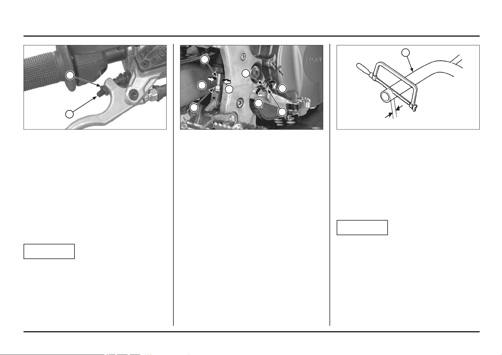
Handlebar position, width and shape
Position the handlebar so that gripping the bar and ope-
rating the controls is comfortable while both seated and
standing, while riding straight ahead and turning.
Handlebar width can be trimmed with a hacksaw to
better your particular shoulder width and riding preferen-
ce. Think this though carefully and cut off just a small
amount at a time from both sides equally.
NOTICE
Chamfer the edges to remove burrs and other irregulari-
ties or roughness after shaping.
An alternate handlebar shape, through varying rise or re-
arward sweep dimensions, will provide further adjustment
to riding position and may better suit your particular body
size or riding style. Each of the ergonomic dimensions
of the motorcycle were determined to suit the greatest
possible number of riders based on an average size rider.
(1) HANDLEBAR(1) LOCK NUT
(2) ADJUSTING BOLT
(A) RAISE THE PEDAL HEIGHT
(B) LOWER THE PEDAL HEIGHT
Brake pedal height
The brake pedal height can be adjusted to the rider’s pre-
ference.
To adjust the rear brake pedal height:
1. Loosen the push rod lock nut and brake pedal adjusting
bolt lock nut. Then turn the both adjusting bolts in
direction “A” to raise the pedal, or in direction “B” to
lower it.
2. Tighten the lock nuts at the desired pedal height.
3. After adjustment, check the brake pedal free play at
the top of the pedal.
Make sure that the clearance between the front adjus-
ting bolt and frame is at least 1 mm (0.04 in).
Front brake lever
The front brake lever free play can be adjusted by turning
the adjuster.
Free play must be adjusted to provide 0.1 – 1.4 mm
(0.004 – 0.055 in) clearance between the end of the ad-
juster and the front brake master cylinder piston.
To increase free play, turn the adjuster clockwise, then
tighten the lock nut securely.
If the brake lever free play exceeds 30 mm (1.2 in) even
though the end of the adjuster and the front brake master
cylinder piston is adjusted to the minimum of 0.1 mm
(0.004 in), there is probably air in the brake system and
it must be bled.
NOTICE
Do not adjust the end of the adjuster and the front brake
master cylinder piston below 0.1 mm (0.004 in).
(1) ADJUSTER
(2) LOCK NUT
A
A
B
B
1
1
2
2
1
1
2
Loading ...
Loading ...
Loading ...