Loading ...
Loading ...
Loading ...
6-6
6-6
Electrical servicing
Self-diagnosis Reset Procedure
After the faulty circuit has been repaired, connect the
PGM-FI warning unit assembly as noted in the previous
step.
Before turning on the power switch, turn the WARN/
RESET switch to the WARN side.
Turn the power switch ON, then turn the WARN/RESET
switch to RESET.
The MIL lights for about 5 seconds.
While the MIL lights, turn the WARN/RESET switch to the
WARN side.
Self-diagnosis memory data is erased if the MIL turns off
and starts blinking.
y The WARN/RESET switch must be switched to WARN
side while the indicator lights. If not, the MIL will not
sart blinking
y Note that the self-diagnosis memory data cannot be
erased if you disconnect the battery from the warning
unit assembly before the MIL starts blinking.
Turn the power switch OFF and disconnect the warning
unit assembly from the motorcycle.
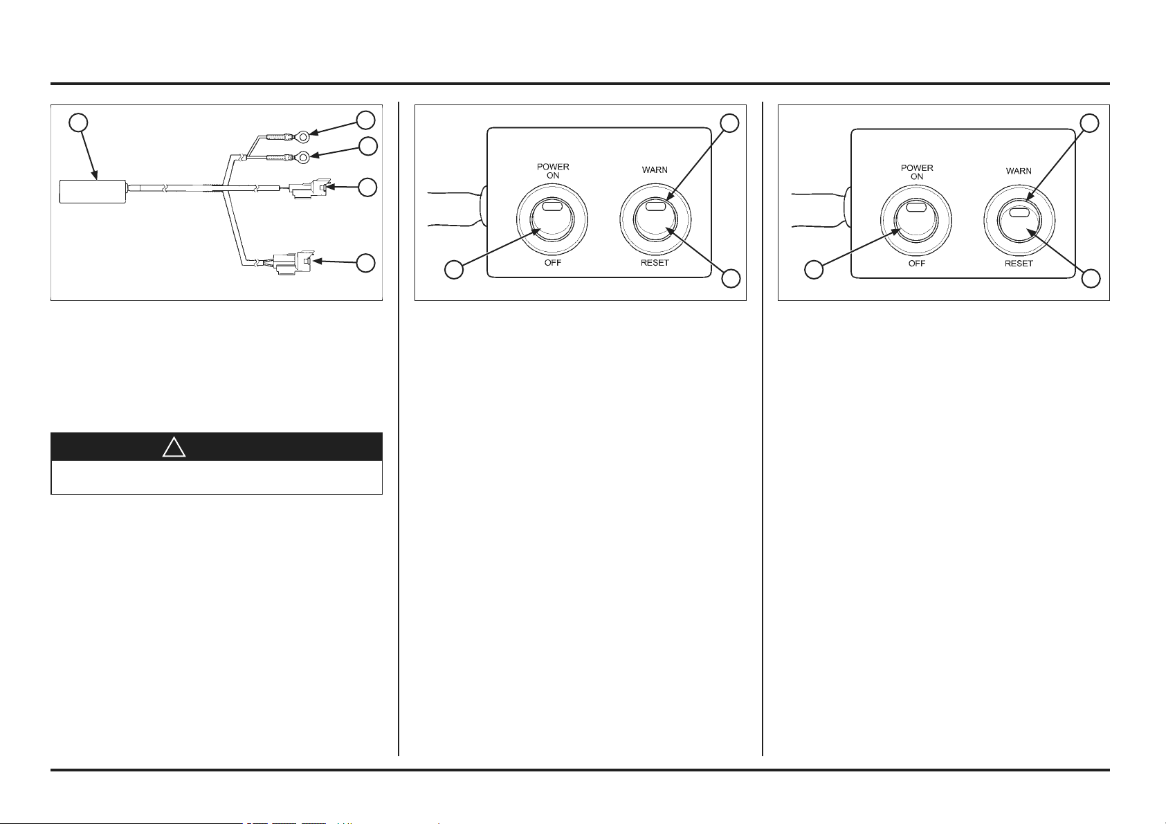
(1) POWER SWITCH
(2) MIL
(3) WARNING/RESET SWITCH
(1) POWER SWITCH
(2) MIL
(3) WARN/RESET SWITCH
Turn the PGM-FI warning unit WARN/RESET switch to the
WARN side as shown.
Turn the power switch ON, check the MIL.
If the ECM has no self diagnosis memory data, the MIL
will illuminate when you turn the power switch ON.
If the ECM has self diagnosis memory data, the MIL will
start blinking when you turn the power switch ON.
Note how many times the MIL blinks, and determine the
cause of the problem (See next page).
(1) PGM WARNING UNIT ASSEMBLY
(2) RED WIRE EYELET
(3) GREEN WIRE EYELET
(4) 2P (BLACK) CONNECTOR
(5) 4P (RED) CONNECTOR
PGM-FI
Self-diagnostic procedure
!
CAUTION
To avoid injury, keep hands and fingers away from the
cooling fan.
If the ECT sensor is faulty, the cooling fan will turn on
when you connect a 12 V battery to the warning unit
terminals.
Disconnect the fuel pump 2P (Black) connector.
Disconnect the condenser 2P (Black) connector and
connect a warning unit connector to the wire harness
side.
Tool:
PGM-FI warning unit assembly 07AMZ-NN4A100
Connect the waring unit 4P (Red) connector to the service
check 4P (Red) connector.
Connect a fully charged 12 V battery to the warning unit
terminals (red wire eyelet to the battery positive terminal
and green wire eyelet to the negative terminal).
5
4
3
2
1
3 3
2 2
1 1
Loading ...
Loading ...
Loading ...