Loading ...
Loading ...
Loading ...
8
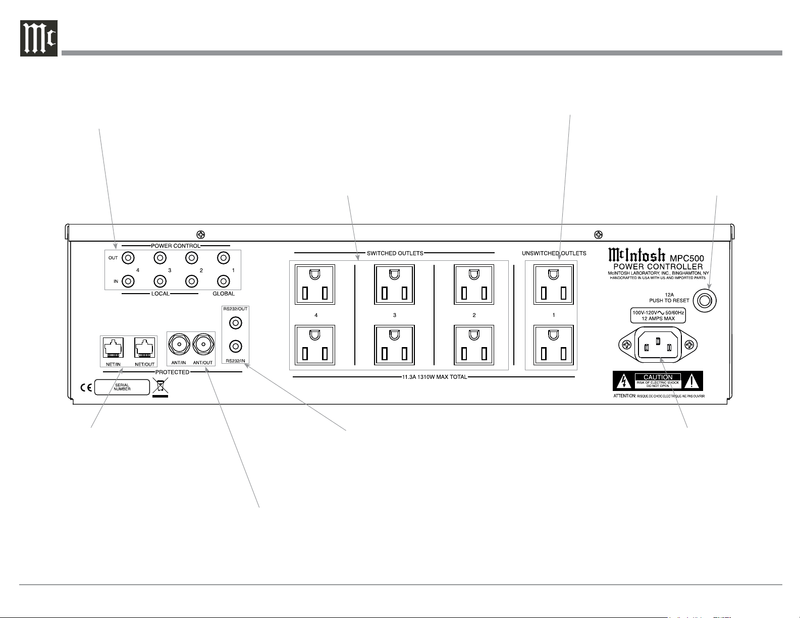
Rear Panel Connections MPC500 (100V-120V)
POWER CONTROL OUTputs send turn On/Off
Signals to a connected McIntosh Component.
POWER CONTROL INputs receive turn On/Off
signals from a McIntosh Component
Connect the MPC500 power cord
to a live AC outlet. Refer to infor-
mation on the back panel of your
MPC500 to determine the correct
voltage for your unit
CIRCUIT BREAKER
PRESS TO RESET if the
MPC500 Power Controller
will not power up
SWITCHED AC OUTLETS (2-4) are con-
trolled by MPC500 POWER CONTROL
Settings and/or the received Power Control
Signal from other components
NETwork/IN provides protection for input Data
Signal from Outside Data Network Source.
NETwork/OUT provides the protected Data
Signal from the Network Input for connection to
Audio/Video Components
ANTenna/IN provides protection for the FM RF
Signal from Outside FM Network Source.
ANTenna/OUT provides the protected FM RF Signal
for connection to Audio/Video Tuner Components
RS232/IN provides protection for the Serial Data Input Signal
from a RS232 Output from another connected Audio/Video
Component.
RS232/OUT provides a protected Serial Data Output Signal
to be connected to other Audio/Video Components
UNSWITCHED AC OUTLETS (1) become
active when the MPC500 AC POWER CORD is
connected to an active external AC Outlet
Loading ...
Loading ...
Loading ...