Loading ...
Loading ...
Loading ...

11
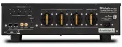
How to Connect MPC500 for (220V-240V)
How to Connect MPC500 for (220V-240V)
Caution: Do not connect the AC Power Cord to the
MPC500 Rear Panel until after the Audio/
Video Components have been Connected to the
MPC500.
The connection instructions below, together with the
MPC500 Connection Diagram located on the sepa-
rate folded sheet “Mc1B”, are an example of a typical
Audio/Video System. The MPC500 has the ability
to automatically switch AC Power On/Off to Com-
ponents connected to the MPC500 SWITCHED AC
OUTLETS (2 thru 4) via the Power Control Con-
nection (1 thru 4). Your system may vary from this,
however the actual components would be connected in
a similar manner. For additional information refer to
“Connector and Cable Information” on page 3.
Power Control Connections:
1. Connect a Control Cable from the A/V Control
Center TRIGger (Power Control) 1 Jack to the
POWER CONTROL INput 2 Jack on the MPC500
for primary listening.
2. Connect a Control Cable from the MPC500
POWER CONTROL OUTput 2 Jack to the Media
Bridge PWR CTRL (Power Control) IN Jack.
3. Connect a Control Cable from the Media Bridge
PWR CTRL (Power Control) OUT Jack to the
AM/FM Tuner Power Control IN Jack.
Network Connections:
Use CAT 5/6 Ethernet Type Cables to provide con-
nections between the MPC500 and all the Network
Connectors on the Audio/Video Components along
with Network Router/Switch and Ethernet Crossover
Adapter.
4. Connect a Ethernet Cable from the Cable Com-
pany Connection unit Net Output Connector, to the
MPC500 NET/IN Connector.
5. Connect a Ethernet Cable from the MPC500 NET/
OUT Connector to the Network Router/Switch and
Ethernet Crossover Adapter Input Connector.
6. Connect Network Cables from the Router/Switch
or Ethernet Crossover Adapter NETWORK Output
connectors to each of the Audio/Video Compo-
nents (A/V Control Center, Media Bridge, and any
addition components) with NETWORK Connec-
tors.
RS232 Connections:
Use either type of RS232 Cables to make the neces-
sary RS232 Connections. Either a 3.5mm stereo mini
phone plug RS232 Cable on both cable ends or when
necessary, a cable with Sub Miniature DB9 Connector
on one end and a 3.5mm stereo mini phone plug on
the other end.
7. Connect the appropriate RS232 Cable from the
A/V Control Center RS232 Connector to MPC500
RS232/IN Connector.
8. Connect the appropriate RS232 Cable from the
MPC500 RS232/OUT Connector to the AM/FM
Tuner RS232 Connector.
Antenna Connections:
Use a RF Cable with “F” Connectors for providing
FM Radio Frequency (or Video) Transmitted Signal
between components.
9. Connect a RF Cable from the Cable Company
Connection unit to the MPC500 ANT/IN Input
Connector.
10. Connect the MPC500 ANT/OUT Connector via
a RF Cable with “F” Connectors to the AM/FM
Tuner FM ANT Connector.
Switched AC Power Outlets:
Use the AC Power Cords that where supplied with
each of the Audio/Video Components in the following
steps:
11. Connect an AC Power Cord from the A/V Control
Center to the MPC500 UNSWITCHED Upper
Outlet Number 1.
12. Connect an AC Power Cord from the Media
Bridge External Power Supply to the MPC500
Switched Outlet Number 2.
13. Connect an AC Power Cord from the AM/FM
Tuner to the MPC500 Switched Outlet Number 3.
14. Optionally, connect an additional Audio/Video
Component AC Power Cords to the MPC500
Switched AC Outlet Number 4. Add up the current
Amperage ratings of the connected components,
making sure that the Total Components do not
exceed a total of 6 Amps.
Loading ...
Loading ...
Loading ...