Loading ...
Loading ...
Loading ...
13
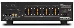
Each of the displays indicate the Status of the
MPC500 AC Power Outlets and the Power Con-
trol Settings for the AC Power Outlets.
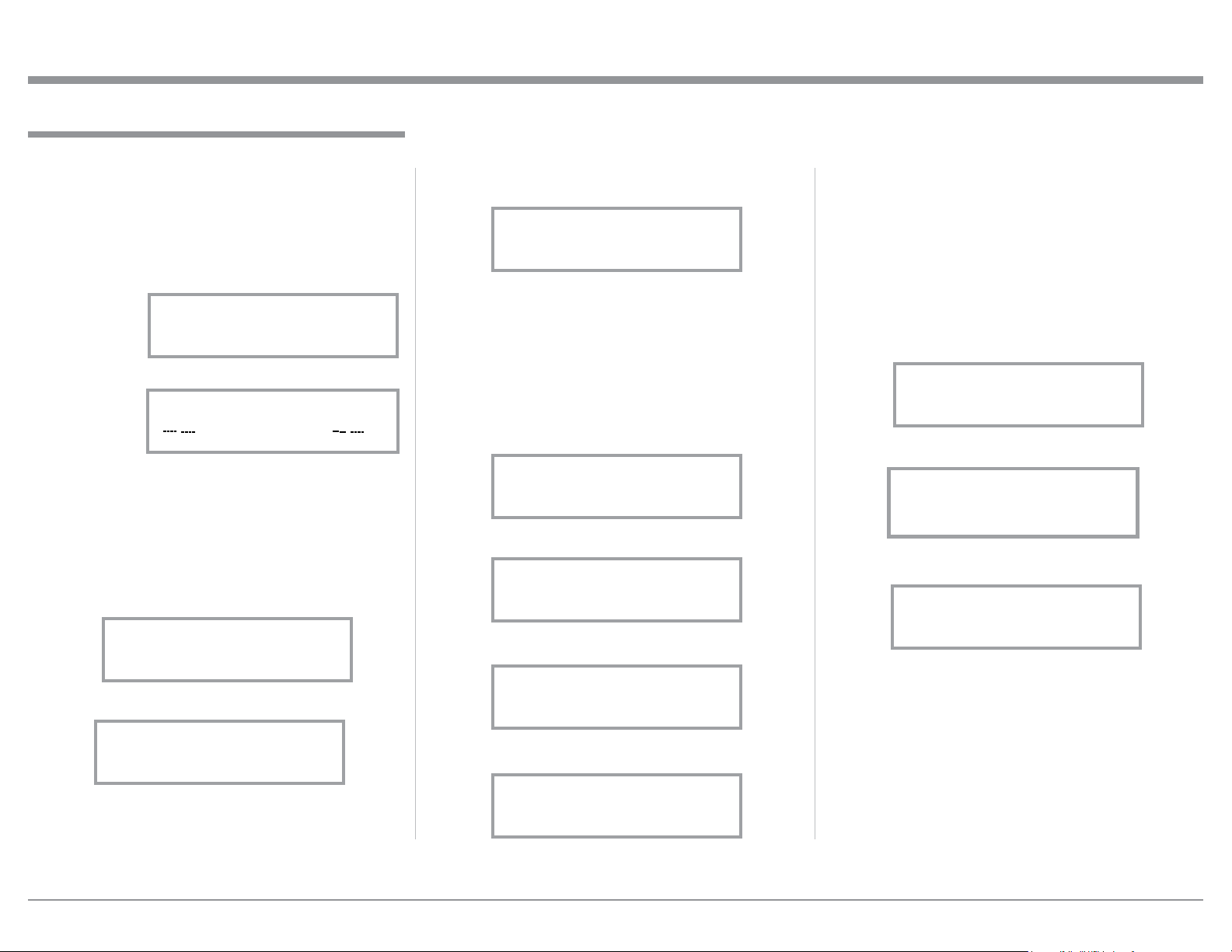
Display Control
After the MPC500 is switched On and the Front Panel
Display has indicated the previous figures (3A, 4A
or 3B/4B), rotate the DISPLAY Control Clockwise to
display additional Function Displays. Refer to figures
9 thru 11.
By using the DISPLAY Control to select Figure
3A/4A, 3B/4B, 9, 10 or 11, it will now determine, when
the MPC500 is switched on, which figure will be dis-
played after Figure 1 and Figure 2 is displayed.
Power On and Off
After the MPC500 is connected for Audio/Video
Components 100V-120V (refer to page 8) or 220V-
240V (refer to page 10), press the OUTLET STATE
Control to switch it On. The Front Panel Display will
indicate the “MPC500” for several seconds and then
followed by “MPC500 --Protected --”. Refer to figures
1 and 2. The
MPC500 will
then measure
the “The AC
Line Voltage
Level” that it is
connected to.
The Front Pan-
el Display will
then indicate
the measured Voltage, for the MPC500 (100V-120V)
or (220V-240V) unit. Refer to figure 3A or figure 4A.
The actual measurements will vary according to the
incoming AC Line Voltage for the building where the
MPC500 and the rest of the Audio/Video Equipment
is physically located.
Note: If during the last time the MPC500 was On
and the selection of the various Setup Operat-
ing Function was previously changed using the
How to Operate
How to Operate
Figure 1
MPC500
Figure 2
MPC500
Protected
AC LINE VOLTAGE
120.0 Volts
Figure 3A
DISPLAY CONTROL, figures 3A or 4A will now
indicate a different display status like figure
3B/4B.
Status of the Power AC Outlets
After the MPC500 has displayed the incoming line
voltage, rotating the OUTLET STATE Control clock-
wise will allow for the indication of the MPC500
Operational Status. Rotating the Control will Display
the following. Refer to figures 5 thru 8.
Figure 5
Outlet 1: On
Power Ctrl: On
Figure 6
Outlet 2: On
Power Ctrl: On
Figure 7
Outlet 3: On
Power Ctrl: On
Figure 8
Outlet 4: On
Power Ctrl: On
Figure 4a
AC LINE VOLTAGE
220.0 Volts
Figure 4A
MOV SURGE STATUS
Protected
Figure 3B/4B
Figure 9
AC LINE CURRENT
1.39 Amps
Figure 10
AC LINE POWER
180.6 Watts
Figure 11
MOV SURGE STATUS
Protected
Loading ...
Loading ...
Loading ...