Loading ...
Loading ...
Loading ...
14
4. Rotate the OUTLET STATE Control to select the
setting of GLOBAL or LOCAL. Refer to figures
19 and 20.
5. Once the new Power Control Setting has been
selected, press the DISPLAY CONTROL.
Setup Display Brightness Configuration
The Front Panel Display Brightness is adjustable via a
Setup Mode of operation.
1. Press DISPLAY CONTROL and then rotate the
control until it displays “DISPLAY Brightness”.
Refer to figure 21.
2. Then rotate the OUTPUT STATE Control clock-
wise to increase the current Brightness Level or
rotate Control Counter Clockwise to reduce the
current Brightness Level.
3. After the Brightness Level has been adjusted to
the desired level, then press the DISPLAY CON-
TROL to end the adjustment of the Brightness
Level.
Setup Operating Mode
After the MPC500 is On and the Front Panel is Dis-
playing Figures 3A/4A, 3B/4B, 9, 10 or 11, it is now
time to operate the MPC500 SETUP Mode. Press
DISPLAY CONTROL and the following is displayed.
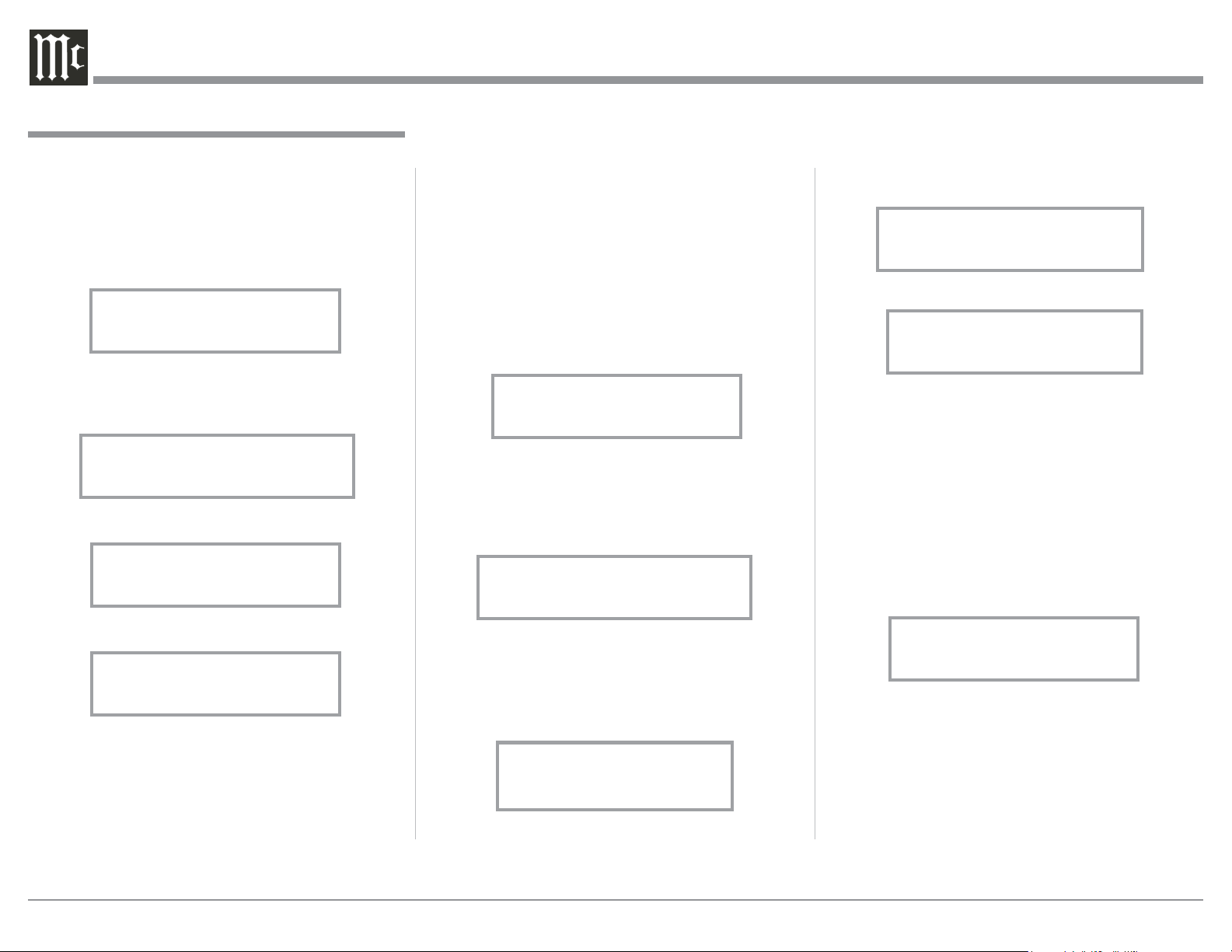
Referring to figure 12 of which is displaying the Ver-
sion Number and Serial Number of this MPC500.
Figures 13 thru 15 are MPC500 Settings where adjust-
ments can be made for each of the operating functions.
Setup Outlet Configuration
The Power Control Output Connections of 2, 3 & 4 on
the MPC500 can be changed from the normal default
settings of ON to a setting of ON, GLOBAL or LO-
CAL. The GLOBAL Setting provides the same Power
How to Operate, con’t
MPC500 V1.00
S/N: _______
Figure 12
SETUP: Outlet Config
(Hold SETUP)
Figure 13
DISPLAY
Brightness
Figure 14
FACTORY RESET
(Hold SETUP)
Figure 15
Control Output Setting as the Power Control 1 Output
of which is On. The LOCAL Setting for the selected
Power Control Output provides the same function as
its Power Control Input Connection.
Follow the steps below to change the current setting
for one or more of the MPC500 Power Control Output
Connectors:
1. After the MPC500 has been switched on for sev-
eral seconds, rotate the OUTLET STATE Control
Clockwise to display the following for Power
Control 2. Refer to figure 16.
2. Press DISPLAY CONTROL and then rotate the
control until it displays “SETUP: Outlet Config
(Hold SETUP)”. Refer to figure 17.
3. Press DISPLAY CONTROL and the Front Panel
Display will indicate the following setting for
Power Control 2. Refer to figure 18.
Figure 16
Outlet 2: On
Power Ctrl: On
SETUP: Outlet Config
(Hold SETUP)
Figure 17
SETUP: Outlet 2
Power Ctrl: On
Figure 18
SETUP: Outlet 2
Power Ctrl: Global
Figure 19
SETUP: Outlet 2
Power Ctrl: Local
Figure 20
DISPLAY
Brightness
Figure 21
Loading ...
Loading ...
Loading ...