Loading ...
Loading ...
Loading ...

3. Connect the test leads to two points on the circuit being tested. If the resistance is lower
than 30Ω±20Ω, the buzzer will sound.
TEST SIGNAL USE
1. RANGE switch to “ ” range.
2. A test signal (50Hz) will appear between “VΩmA” and “COM” jacks, the output voltage is
approximately 5V p-p with 50KΩ impedance.
BATTERY TEST
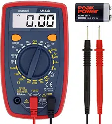
1. Connect the black test lead to the "COM" jack and the red test lead to the "VΩmA" jack.
2. According to the different type of the battery (1.5V, 9V, 12V) to be tested, set the range
switch to the desired DC Voltage range.
3. Connect the test leads to the battery to be tested. The red lead will touch the positive
end of the battery, the black lead will touch the negative end.
4. The DC Voltage measurement of the battery will be displayed.
BATTERY AND FUSE REPLACEMENT
If the low battery indicator “ ” appears on the multimeter’s screen, replace the battery
immediately.
To replace the battery:
1. Remove the screw at the top of the back of the multimeter. Remove the battery cover.
2. Remove the old battery and replace it with a new 9V battery.
3. Put the battery cover back on and put the screw securely back into place.
The fuse rarely needs to be replaced. If the fuse blows it is almost always due to operator error.
To test if the fuse needs to be replaced, use the following steps:
1. Remove the test leads from the multimeter.
2. Turn the rotary switch to the 200mA position.
3. Use another multimeter to measure the resistance of the “VΩmA” terminal to the “COM”
terminal.
○ If the fuse is still functional, the reading should display between 0Ω and 10Ω.
○ If the display indicates an overload, replace the fuse and test again.
To replace the old fuse:
1. Remove the screw on the top of the multimeter’s back. Then remove the battery from the
battery terminal.
2. Remove the two screws at the bottom of the multimeter’s back.
3. Remove the rubber bumper running along the outside of the multimeter, then separate
the housing from the multimeter. Doing so should reveal the multimeter’s circuit board.
Loading ...
