Loading ...
Loading ...
Loading ...

DC CURRENT MEASUREMENT
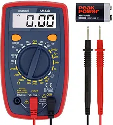
1. Connect the red test lead to “VΩmA” (center plug) and the black test lead to “COM” (right
plug). For measurements between 200mA and 10A, connect the red test lead to “10A”
(left plug).
Note: For 10A measurements, only take readings for up to 10 seconds, and allow 15
minutes between tests. This prevents the device from overloading and overheating.
2. Set the manual range switch to the desired DC Current position. The DC Current
positions are located at the right side of the range of the range, marked with a yellow
“A⎓”.
Note:If you are measuring an unknown current, set the range switch to the highest
range and reduce it until a satisfactory reading is obtained.
3. Open the circuit being measured and connect the test leads in series with the load being
measured. The results will appear on the digital display.
4. The “10A” function is designed for intermittent use only. Maximum contact time of the
test leads with the circuit is 10 seconds.
RESISTANCE MEASUREMENT
1. Connect the red test lead to “VΩmA” (center plug) and the black test lead to “COM” (right
plug).
2. Set the manual range switch to the desired Resistance position. The Resistance
positions are located at the bottom and bottom left of the range, marked with a yellow
“Ω”.
Note: If you are measuring an unknown Resistance, set the range switch to the highest
range and reduce it until a satisfactory reading is obtained.
3. If the resistance being measured is connected to a circuit, turn off power and discharge
all capacitors before measurement.
4. Connect test leads to circuit being measured and the results will show on the digital
display.
DIODE MEASUREMENT
1. Connect the red test lead to “VΩmA” (center plug) and the black test lead to “COM” (right
plug).
2. Set the manual range switch to “ ”, located on the bottom right of the dial.
3. Connect the red test lead to the anode of the diode to be measured and black test lead
to cathode.
4. The forward voltage drop in mV will be displayed. If the diode is reversed, an error will
read “1” on the device screen.
AUDIBLE CONTINUITY TEST
1. Connect the red test lead to “VΩmA” (center plug) and the black test lead to “COM” (right
plug).
2. Set the manual range switch to “ ”, located on the bottom right of the dial.
Loading ...
Loading ...
