Loading ...
Loading ...
Loading ...
94
HR UNIT PCB
ENGLISH
Group Number setting
Group Number setting for Indoor Units
- Confirm the power of whole system(Indoor Unit, Outdoor Unit) is OFF, otherwise turn off.
- The communication cables connected to CEN.A and CEN.B terminal should be connected to
central control of Outdoor Unit with care for their polarity (A-A, B-B ).
- Turn the whole system on.
- Set the group and Indoor Unit number with a wired remote control.
- To control several sets of Indoor Units into a group, set the group ID from 0 to F for this pur-
pose.
Outdoor Units (External PCB)
Example) Group number setting
1
st
number indicate the group number
2nd number point out indoor unit number
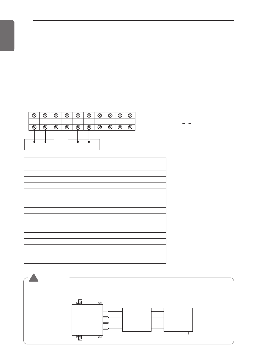
SODU.B SODU.A IDU.B IDU.A CEN.B CEN.A DRY1 DRY2 GND 12V
B(D) A(C) BA
1 F
Group Indoor unit
Group recognizing the central controller
No.0 group (00~0F)
No.1 group (10~1F)
No.2 group (20~2F)
No.3 group (30~3F)
No.4 group (40~4F)
No.5 group (50~5F)
No.6 group (60~6F)
No.7 group (70~7F)
No.8 group (80~8F)
No.9 group (90~9F)
No. A group (A0~AF)
No. B group (B0~BF)
No. C group (C0~CF)
No. D group (D0~DF)
No. E group (E0~EF)
No. F group (F0~FF)
Valve (04)
EX)
Valve (03)
Valve (02)
Valve (01)
Indoor unit (04)
Indoor unit (03)
Indoor unit (02)
Indoor unit (01)
Central control address
HR unit
WARNING
• Valve address and central control address of its corresponding indoor unit should be set identi-
cal in manual addressing.
!
Loading ...
Loading ...
Loading ...