Loading ...
Loading ...
Loading ...
HR UNIT PCB
89
ENGLISH
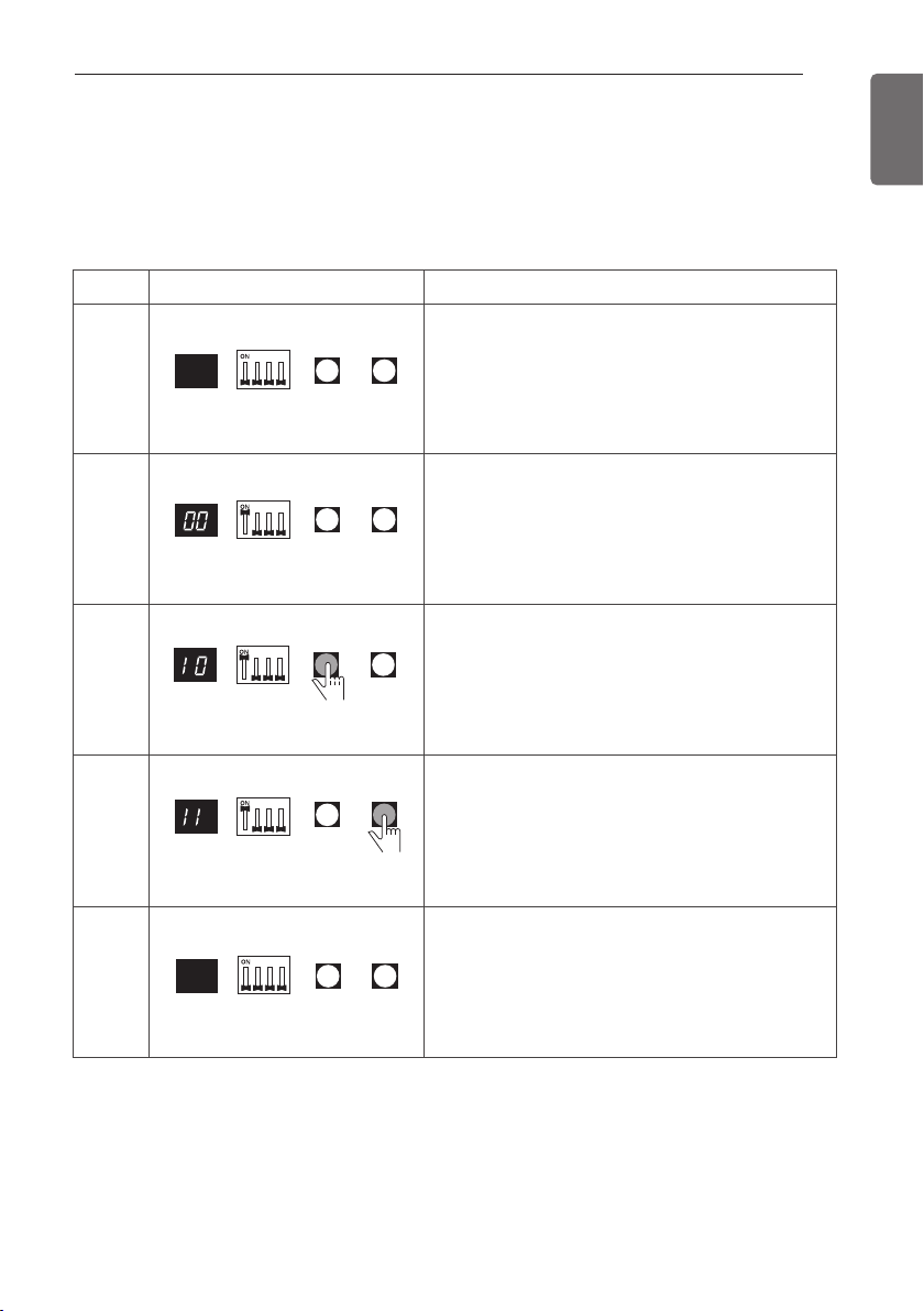
Example of manual valve addressing (Non-Zoning setting)
(In case that an indoor unit of central control address "11" is connected to a valve #1 of an HR
unit)
- Prerequisite for manual valve addressing: central control address of each indoor unit must be
preset differently at its wired remote control.
- Operation: None
- Display: None
No.
1
2
3
4
5
Display and setup
Setup and Contents
- Operation: Turn dip S/W No.1 on to address valve
#1
- Display: Existing value saved in EEPROM is dis-
played in
7-SEG.
- Operation: Set the digit of 10 to the number in
Group High data of the wired remote control con-
nected to the corresponding indoor unit to the
valve #1 by pressing left tack S/W.
- Display: Digit increasing with the times of press-
ing tack S/W is displayed in left 7-SEG
- Operation: Set the digit of 1 to the number in
Group Low data of the wired remote control con-
nected to the corresponding indoor unit to the
valve #1 by pressing right tack S/W.
- Display: Digit increasing with the times of press-
ing tack S/W is displayed in right 7-SEG
- Operation: Turn dip S/W No.1 off to save the ad-
dress of
valve #1
- Display: "11" displayed in 7-SEG disappears
7-SEG SW01M SW03M SW04M
7-SEG SW01M SW03M SW04M
7-SEG SW01M SW03M SW04M
7-SEG SW01M SW03M SW04M
7-SEG SW01M SW03M SW04M
- Above setup must be done for all HR unit valves.
- The valve that is not connected with any indoor unit should be addressed with any other num-
ber than used address numbers of the valves connected with indoor units.
(The valves does not work if the address numbers are same.)
Loading ...
Loading ...
Loading ...