Loading ...
Loading ...
Loading ...
30
Installation
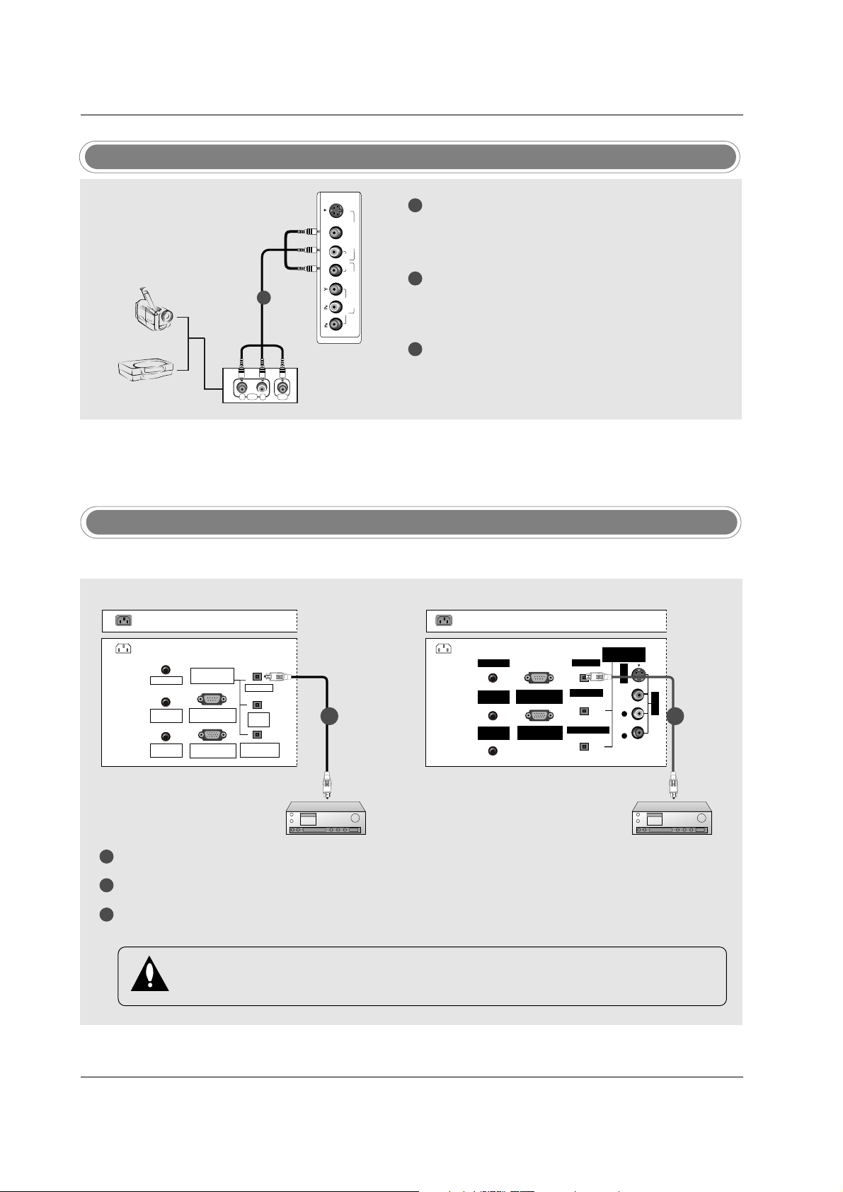
Digital Audio Output
RL
AUDIO VIDEO
R
(MONO)
L VIDEO
S-VIDEO
VIDEO
AUDIO
COMPONENT 2
VIDEO 2
Camcorder
Video Game Set
TV Side
1
1
2
3
Connect the AUDIO/VIDEO jacks between TV
and external equipment. Match the jack colors
(Video = yellow, Audio Left = white, and Audio
Right = red).
Select Video2 input source with using the
TV/VIDEO button on the remote control.
- If connected to VIDEO1 input, select Video1
input source.
Operate the corresponding external equipment.
Refer to external equipment operating guide. For
connection instructions to operate the TV Guide
On Screen system, see page 42~43.
1
2
3
Connect one end of an optical cable to the TV Digital Audio Optical Output port.
Connect the other end of the optical cable to the digital audio optical input on the audio equipment.
See the external audio equipment instruction manual for operation. When connecting with external audio
equipments, such as amplifiers or speakers, please turn the TV speakers off. (Refer to p.80)
AC IN
G-LINK
DIGITAL AUDIO
(OPTICAL)
DVI
INPUT
COMPONENT1
INPUT
OUTPUT
RGB INPUT
(PC/DTV INPUT)
RS-232C INPUT
(CONTROL/SERVICE)
PC AUDIO
INPUT
REMOTE
CONTROL
G-LINK
DIGITAL AUDIO
(OPTICAL)
OUTPUT
VIDEO1
RGB INPUT
(PC/DTV INPUT)
RS-232C INPUT
(CONTROL/SERVICE PORT)
PC AUDIO
INPUT
REMOTE
CONTROL
S-VIDEO
AUDIO VIDEO
(MONO)
RL
DVI INPUT
COMPONENT1 INPUT
AC IN
- Send the TV’s audio to external audio equipment (stereo system) via the Digital Audio Output Optical port.
CAUTION
Do not look into the optical output port. Looking at the laser beam may damage your vision.
External AV Source Setup
1/2 1/2
32, 37, 42 inch TV Back
26 inch TV Back
Loading ...
Loading ...
Loading ...