Loading ...
Loading ...
Loading ...
27
Installation
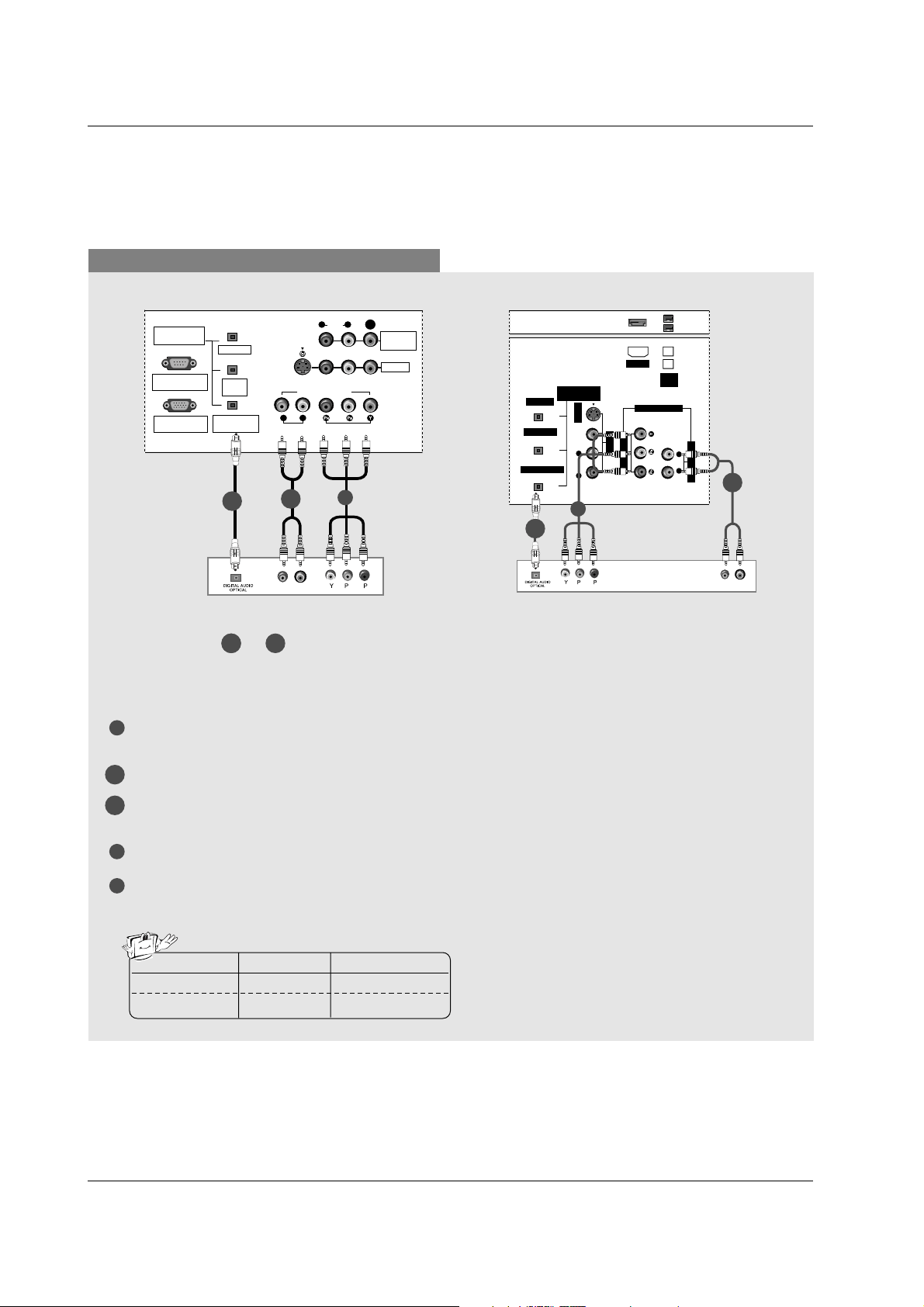
When connecting with a Component cable
1
3
4
Connect the video outputs (Y, PB, PR) of the digital set-top box to the COMPONENT1 VIDEO INPUT jacks
on the set.
Connect the audio output of the digital set-top box to the COMPONENT1 AUDIO INPUT jacks on the set.
Connect the optical audio output of the digital set-top box to the DIGITAL AUDIO COMPONENT1 INPUT
jack on the set.
Turn on the digital set-top box. (Refer to the owner’s manual for the digital set-top box.)
Select Component 1 input source with using the TV/VIDEO button on the remote control.
- If connected to COMPONENT2 input, select Component 2 input source.
B
R
(R) AUDIO (L)
DIGITAL AUDIO
(OPTICAL)
DVI
INPUT
COMPONENT1
INPUT
OUTPUT
VIDEO1
RGB INPUT
(PC/DTV INPUT)
RS-232C INPUT
(CONTROL/SERVICE)
AUDIO INPUT
AUDIO
(MONO)
VIDEO INPUT
COMPONENT1
RL
RL
S-VIDEO
MONITOR
OUT
VIDEO
DIGITAL AUDIO
(OPTICAL)
OUTPUT
VIDEO1
AUDIO INPUT
VIDEO INPUT
RL
S-VIDEO
IEEE
1394
AUDIO VIDEO
(MONO)
RL
HDMI
DVI INPUT
COMPONENT1 INPUT
COMPONENT1
B
R
(R) AUDIO (L)
Signal
480i
480p/720p/1080i
Component1/2
Yes
Yes
RGB-DTV, HDMI/DVI
No
Yes
1
Digital Set-top Box
Digital Set-top Box
2-1
2-1
2-2
2-2
1
2-1
2-2
Select or , depending on your digital set-top box connector.
2-1 2-22-1
32, 37, 42 inch TV Back
26 inch TV Back
Loading ...
Loading ...
Loading ...