Loading ...
Loading ...
Loading ...
22
Installation
- To avoid picture noise (interference), leave an adequate distance between the VCR and TV.
- Typically a frozen still picture from a VCR. If the 4:3 picture format is used; the fixed images on the sides
of the screen may remain visible on the screen.
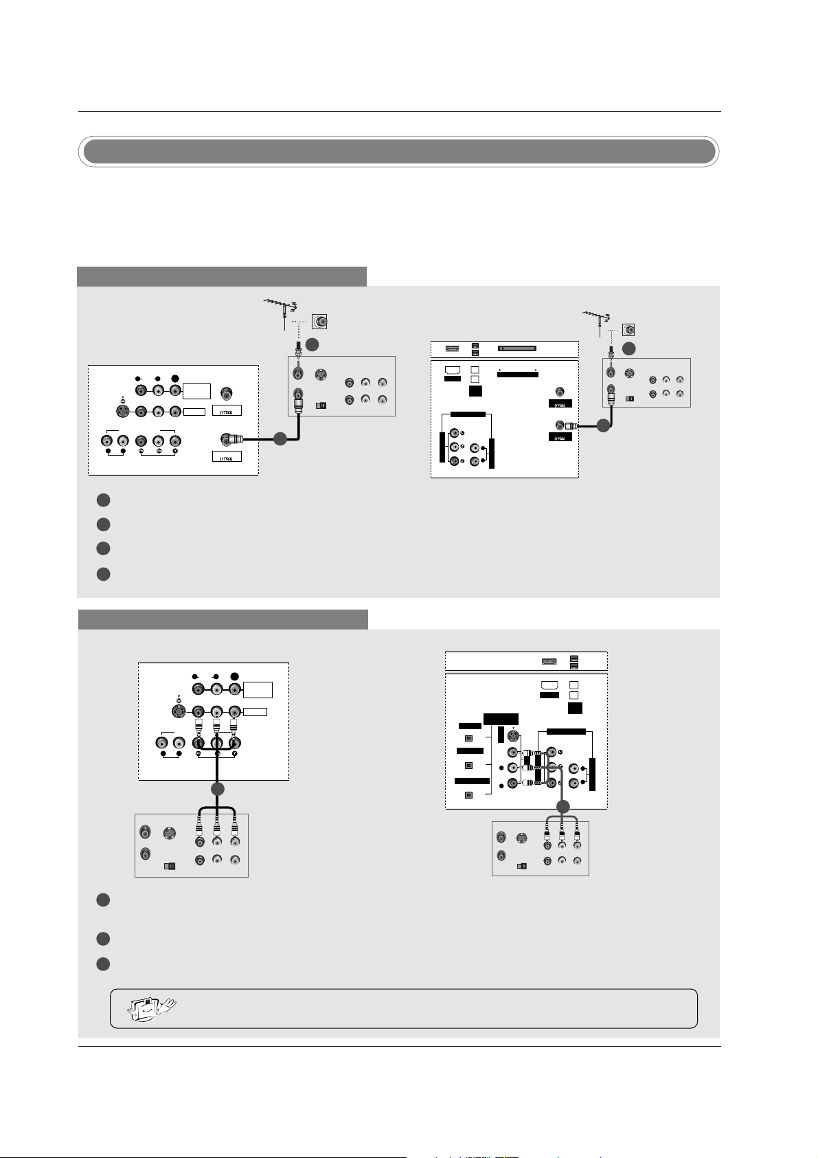
VCR Setup
When connecting with an antenna
1
2
3
4
S-VIDEO
OUT
IN
(R) AUDIO (L) VIDEO
34
OUTPUT
SWITCH
ANT OUT
ANT IN
ANTENNA
VIDEO1
AUDIO INPUT
AUDIO
(MONO)
VIDEO INPUT
COMPONENT1
RL
RL
S-VIDEO
CABLE
MONITOR
OUT
VIDEO
Connect the RF antenna out socket of the VCR to the Antenna socket on the set.
Connect the antenna cable to the RF antenna in socket of the VCR.
Set VCR output switch to 3 or 4 and then tune TV to the same channel number.
Insert a video tape into the VCR and press PLAY on the VCR. (Refer to the VCR owner’s manual.)
VCR
When connecting with a RCA cable
S-VIDEO
OUT
IN
(R) AUDIO (L) VIDEO
34
OUTPUT
SWITCH
ANT OUT
ANT IN
VIDEO1
AUDIO INPUT
AUDIO
(MONO)
VIDEO INPUT
COMPONENT1
RL
RL
S-VIDEO
MONITOR
OUT
VIDEO
VCR
VCR
32, 37, 42 inch TV Back
26 inch TV Back
32, 37, 42 inch TV Back
1
2
3
Connect the AUDIO/VIDEO jacks between TV and VCR. Match the jack colors (Video = yellow, Audio Left
= white, and Audio Right = red)
Insert a video tape into the VCR and press PLAY on the VCR. (Refer to the VCR owner’s manual.)
Select Video1 input source using the TV/VIDEO button on the remote control.
- If connected to VIDEO2, select Video2 input source.
• If you have a mono VCR, connect the audio cable from the VCR to the AUDIO L/MONO jack
of the set.
1
2
ANTENNA
AUDIO INPUT
VIDEO INPUT
RL
CableCARD
IEEE
1394
CABLE
HDMI
COMPONENT1
S-VIDEO
OUT
IN
(R) AUDIO (L) VIDEO
34
OUTPUT
SWITCH
ANT OUT
ANT IN
DIGITAL AUDIO
(OPTICAL)
OUTPUT
VIDEO1
AUDIO INPUT
VIDEO INPUT
RL
S-VIDEO
IEEE
1394
AUDIO VIDEO
(MONO)
RL
HDMI
DVI INPUT
COMPONENT1 INPUT
COMPONENT1
S-VIDEO
OUT
IN
(R) AUDIO (L) VIDEO
34
OUTPUT
SWITCH
ANT OUT
ANT IN
VCR
2
1
1
26 inch TV Back
1
Loading ...
Loading ...
Loading ...