User Manual
Before you start
Read the entire document
CAUTION:
- Installation must be carried out by a certified electrician and must comply with national and local electrical codes
- To prevent severe shock or electrocution, always out the power at the service panel before working with wiring
- Use this thermostat for resistive loads only
- Do NOT install the thermostat in an area where it can be exposed to water or rain
- Avoid locations where there are air drafts (top of staircase, air outlet), dead air spots (behind a door), direct sunlight or concealed chimney or stove pipes.
- For a new installation, choose a location about 5 tt (1.5 m) above the floor.
- Install the thermostat on an inside wall facing the heating system
- Install the thermostat onto an electrical box.
- Use special COIALUR solderless connectors if you connect the thermostat to aluminum wires.
- Keep the thermostats top and bottom air vents (openings) clean and unobstructed at all times.
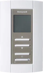
Controls and display
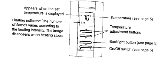
Temperature Display and Setting
The thermostat usually displays the room temperature. To view the set (desired) temperature, press either of the  buttons once. The set temperature is displayed for 5 seconds.
To set a new temperature, press one of the AY buttons repeatedly until the desired temperature is displayed. To scroll faster, press and hold the button.
Backlight
The display iluminates for 5 seconds when the backlight button is pressed.
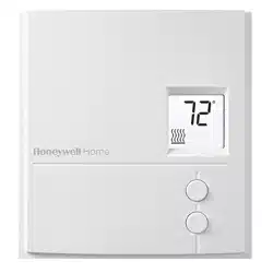
When either of the buttons is pressed, the display Iluminates for 10 seconds. The setpoint temperature appears for the first 5 seconds, then the current temperature is displayed
On/Off Switch
You can set the thermostat to Off to cut power to the heating system when it is not in use (e.g. In summer). The thermostat screen becomes blank but all settings are saved.
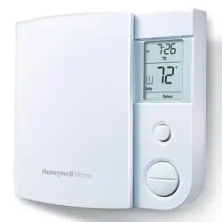
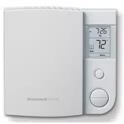
About your thermostat
This thermostat can be connected to an electric heater to control the room temperature.
Supplied Parts
- One (1) thermostat
- Two (2) mounting screws
- Four (4) solderless connectors for copper wires
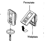
Installing the thermostat
- Tum the heating system off at the main electrical panel
- Loosen the bottom screw and remove the thermostat faceplate from its wallplate. (The screw cannot be completely removed.)
- Connect the thermostat to the load and to the power supply
- Install the walplate to an electrical box using the provided screws.
- Set the configuration switch .
- Install the faceplate back on the wallplate and tighten the screw. If there is a sticker on the screen, pool it off.
- Return power to the heating system at the main electrical panel.
Setting the configuration switch
The configuration switch is located at the back of the control module (faceplate). The switch allows you to select between "C and "F”
-840348.png)
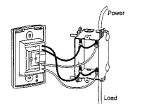
Wiring diagram
NOTE: Connect the wires using the provided solderless connectors for copper wires.
Error Messages
Code – LO
- The measured temperature is below the display range. Heating is activated.
Code – HI
- The measured temperature is above the display range. Heating is deactivated.
Code – Er
- Verify the thermostat and sensor connections. Heating is deactivated.
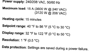
Specisications
Warranty
Honeywell warrants this product, excluding battery, to be free from defects in the workmanship or materials, under normal use and service, for a period of five (5) years from the date of purchase by the consumer. If at any time during the warranty period the product is determined to be defec- tive or malfunctions, Honeywell shall repair or replace it (at Honeywell's option).
If the product is defective.
i) return with a bil of sale or other dated proof of purchase, to the place from which you purchased it, or
ii) call Honeywell Customer Care at 1-800-458-1502. Customer Care wit make the determination whether the product should be returned to the following address: Honeywell Return Goods, Dock 4 MIN10-3860, 1885 Douglas Dr N, Golden Valley, MN 55422, or whether a replace- ment product can be sent to you.
This warranty does not cover removal or reinstallation costs. This warranty shall not apply is shown by Honeywell that the defect or malfunction was caused by damage which occurred while the product was in the possession of a consumer.
Honeywell's sole responsibility shall be to repair or replace the product within the terms stated above. HONEYWELL SHALL NOT BE LIABLE FOR ANY LOSS OR DAMAGE OF ANY KIND, INCLUDING ANY INCIDENTAL OR CONSEQUENTIAL DAMAGES RESULTING DIRECTLY OR INDI RECTLY, FROM ANY BREACH OF ANY WARRANTY, EXPRESS OR IMPLIED, OR ANY OTHER FAILURE OF THIS PRODUCT. Some states do not allow the exclusion or limitation of incidental or consequential damages, so this fimitation may not apply to you.
THIS WARRANTY IS THE ONLY EXPRESS WARRANTY HONEYWELL MAKES ON THIS PRODUCT. THE DURATION OF ANY IMPLIED WARRANTIES, INCLUDING THE WARRANTIES OF MERCHANTABILITY AND FITNESS FOR A PARTICULAR PURPOSE, IS HEREBY LIMITED TO THE FIVE-YEAR DURATION OF THIS WARRANTY. Some states do not allow limitations on how long an implied warranty lasts, so the above limi tation may not apply to you.
This warranty gives you specific legal rights, and you may have other rights which vary from state to slate.