Product may vary slightly from the item pictured due to model upgrades.
Read all instructions carefully before using this product.
Retain this owner’s manual for future reference.
NOTE:
This manual may be subject to updates or changes. Up to date manuals are available through our
website at www.lifespanfitness.com.au
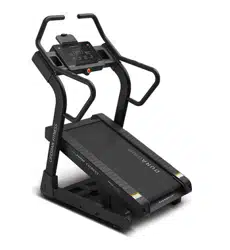
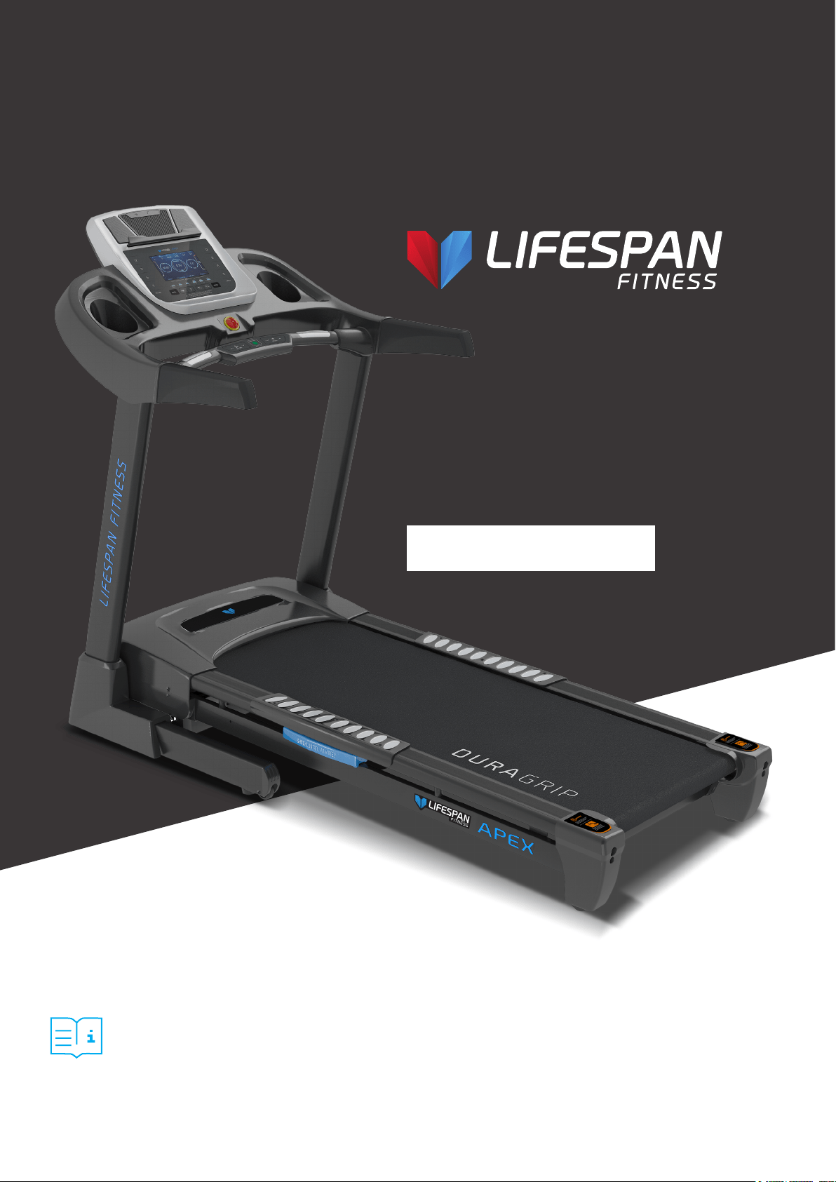
Apex
Treadmill
USER MANUAL

2
TABLE OF
CONTENTS
I. Important Safety Instructions . . . . . . . . . . . . . . . . . . . . . . . . . . . . . . . 03
II. Important Electrical Information . . . . . . . . . . . . . . . . . . . . . . . . . . . . 05
III. Important Operating Instructions . . . . . . . . . . . . . . . . . . . . . . . . . . . 06
IV. Assembly Instructions . . . . . . . . . . . . . . . . . . . . . . . . . . . . . . . . . . . . . . . 07
V. Folding Instructions . . . . . . . . . . . . . . . . . . . . . . . . . . . . . . . . . . . . . . . . . . 11
VI. Operation Guide . . . . . . . . . . . . . . . . . . . . . . . . . . . . . . . . . . . . . . . . . . . . . . 13
VII. Exercise Guide . . . . . . . . . . . . . . . . . . . . . . . . . . . . . . . . . . . . . . . . . . . . . . . . 25
VIII. Maintenance Instructions . . . . . . . . . . . . . . . . . . . . . . . . . . . . . . . . . . . 27
IX. Replacing Motor Brushes . . . . . . . . . . . . . . . . . . . . . . . . . . . . . . . . . . . . 31
X. Exploded Diagram . . . . . . . . . . . . . . . . . . . . . . . . . . . . . . . . . . . . . . . . . . . 34
XI. Parts List . . . . . . . . . . . . . . . . . . . . . . . . . . . . . . . . . . . . . . . . . . . . . . . . . . . . . 35
XII. Trouble Shooting . . . . . . . . . . . . . . . . . . . . . . . . . . . . . . . . . . . . . . . . . . . . . 37
XIII. Warranty . . . . . . . . . . . . . . . . . . . . . . . . . . . . . . . . . . . . . . . . . . . . . . . . . . . . 38
XIV. Hand Pulse Technology . . . . . . . . . . . . . . . . . . . . . . . . . . . . . . . . . . . . . 39
| TABLE OF CONTENTS

3IMPORTANT SAFETY INSTRUCTIONS |
I. IMPORTANT SAFETY
INSTRUCTIONS
WARNING: Read all instructions before using this treadmill.
It is important your treadmill receives regular maintenance to prolong its useful life. Failing to
regularly maintain your treadmill may void your warranty.
DANGER
To reduce the risk of electric shock disconnect your treadmill from the electrical outlet prior to
cleaning and/or service work.
DO NOT USE AN EXTENSION CORD:
DO NOT ATTEMPT TO DISABLE THE GROUNDED PLUG BY USING IMPROPER ADAPTERS OR IN ANY
WAY MODIFY THE CORD SET.
• Install the treadmill on a flat level surface with access to a 220-240 volt (50/60Hz), grounded outlet.
• Do not operate treadmill on deeply padded, plush or shag carpet. Damage to both carpet and
treadmill may result.
• Do not block the rear of the treadmill. Provide a minimum of 1 metre clearance between the rear of the
treadmill and any fixed object.
• Place your unit on a solid, level surface when in use.
• When running, make sure the plastic clip is fastened on your clothing. It is for your safety, should you
fall or move too far back on the treadmill.
• Keep hands away from all moving parts.
• Never operate the treadmill if it has a damaged power cord or plug. When damaged, these must be
replaced by the manufacturer, its service agent or similarly qualified persons in order to avoid a
hazard.
• Keep the cord away from heated surfaces.
• Do not operate where aerosol spray products are being used or where oxygen is being administered.
Sparks from the motor may ignite a highly gaseous environment.
• Never drop or insert any object into any openings.

4
• The treadmill is intended for in-home use only and is not suitable for commercial environments.
• To disconnect, turn all controls to the off position, remove the safety key, and then remove the plug
from the outlet.
• The pulse sensors are not medical devices. Various factors, including the user’s movement, may
affect the accuracy of heart rate readings. The pulse sensors are intended only as exercise aids in
determining heart rate trends in general.
• Use the handrails provided; they are for your safety.
• Wear proper shoes. High heels, dress shoes, sandals or bare feet are not suitable for use on your
treadmill. Quality athletic shoes are recommended to avoid leg fatigue.
• Before undertaking any type of exercise program, it is recommended that you consult a doctor.
• Injuries to health may result from incorrect or excessive training.
• This appliance is not intended for use by persons (including children) with reduced physical, sensory
or mental capabilities, or lack of experience and knowledge, unless they have been given supervision
or instruction concerning use of the appliance by a person responsible for their safety.
• WARNING: Heart rate monitoring systems may be inaccurate. If you feel faint stop exercising
immediately.
• Children should not be allowed on or around the equipment, even when not in use.
• Children should be supervised to ensure that they do not play with this machine.
• Loose-fitting clothing or jewellery that could become an entanglement hazard should not be worn.
• Training shoes should be worn when using the equipment.
• Equipment must be used on a level and stable surface.
• All fixings should be checked before the equipment is used.
• All literature relating to the use of the equipment should be retained for future reference.
• Recommended operating temperature: 5-40°C.
| IMPORTANT SAFETY INSTRUCTIONS
Remove the safety key after use to prevent unauthorized
treadmill operation.

5IMPORTANT ELECTRICAL INFORMATION |
II. IMPORTANT ELECTRICAL
INFORMATION
• Route the power cord away from any moving part of the treadmill including the elevation mechanism
and transport wheels.
• NEVER remove any cover without first disconnecting AC power.
• NEVER expose this treadmill to rain or moisture. This treadmill is not designed for use outdoors, near
a pool, or in any other high humidity environment.
• This is a high-power item; please do not share the same outlet with other high-power machines such
as, fridges, air conditioning etc. Please choose an outlet exclusively for the machine and make sure
the fuse is 10A.
WARNING!

6 | IMPORTANT OPERATING INSTRUCTIONS
III. IMPORTANT OPERATING
INSTRUCTIONS
• Understand that changes in speed and incline do not occur immediately. Set your desired speed on
the computer console and release the adjustment key. The computer will obey the command
gradually.
• Use caution while participating in other activities while walking on your treadmill, such as watching
television, reading, etc. These distractions may cause you to lose balance or stray from walking in the
centre of the belt; which may result in serious injury.
• This unit starts with at a very low speed. It is recommended to stand on the side rails and only step
on the treadmill as it is moving on a slow speed. This will prolong the life of your motor and run the
belt smoothly.
• In order to prevent losing balance and suffering unexpected injury, never mount or dismount the
treadmill while the belt is moving at high speeds.
• Always hold on to handrail while making control changes.
• A safety key is provided with this machine. Remove the safety key will stop the walking belt
immediately; the treadmill will shut off automatically. Inserting the safety key will reset the display.
• Do not use excessive pressure on console control keys. They are precision set to function properly
with little finger pressure.
• Replace any defective components immediately. The machine must be kept out of use until repaired.
• Belt wear-in period: all treadmills make a certain type of thumping noise due to the belt riding over
the rollers, especially new treadmills. This noise will diminish over time, although may not completely
go away. The belt will stretch over time, causing it to ride smoother over the rollers.
7ASSEMBLY INSTRUCTIONS |
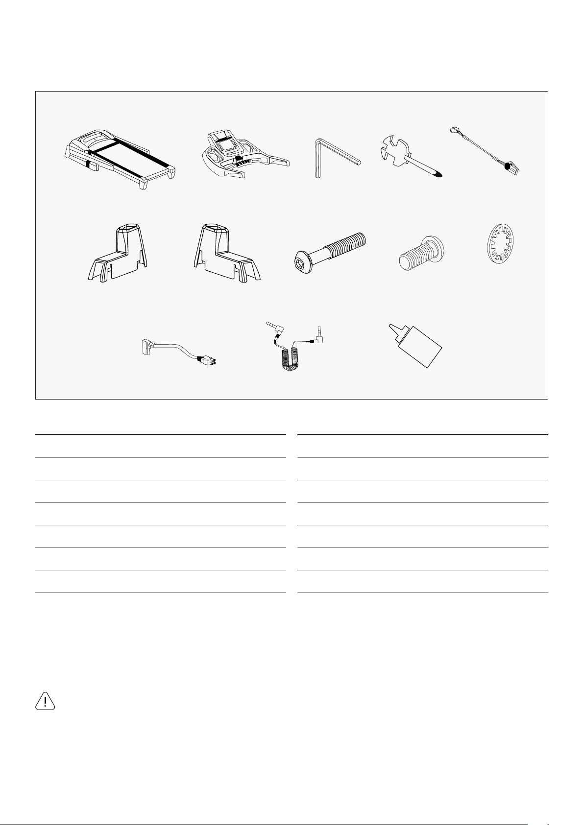
IV. ASSEMBLY INSTRUCTIONS
A02
C08
E
C09
D21
B12
D46
D38
B13
D50
G
C31
D64
6#Allen Wrench 5mm 1pc
Wrench screw Driver S=13, 14, 15 1pc
ASSEMBLY TOOLS:
Do not connect power before completing assembly
WARNING!
No. Description Specs Qty
A02 Main frame 1
E Console 1
B12 Allen wrench 5mm 1
B13 Wrench with Screw Driver S=13, 14, 15 1
C31 Safety key 1
C08 Left upright tube cover 1
C09 Right upright tube cover 1
No. Description Specs Qty
D46 Bolt M8*50 2
D50 Bolt M8*15 6
D64 Lock washer 8 8
D21 Power wire 1
D38 MP3 connecting wire 1
G Lubricant oil 1
8 | ASSEMBLY INSTRUCTIONS
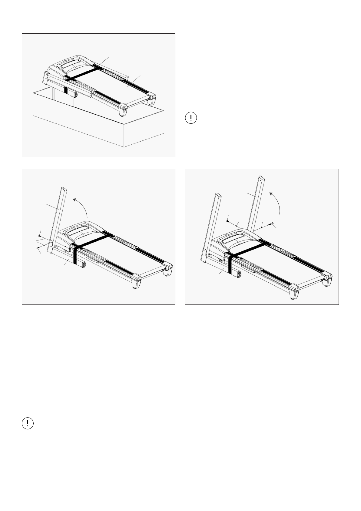
STEP 2
NOTE:
During assembly, support the Upright Tubes (A05 and A06) with your hand to prevent
them from falling down.
STEP 1
1. Open the carton and remove all contents.
Place the Main Frame (A02) on level ground and
ensure that you have a clean work space that
has adequate space.
For safety reasons, do NOT cut the Packing
Belt (F) until you’ve completed assembly.
F
A02
A05
D50
D64
D46
A01
NOTE:
A06
D50
D64
A01
D64
D46
1. Lift the Left Upright Tube (A05) upwards. See Figure 1.
2. Fix the Left Upright Tube (A05) to the Base Frame (A01). Use 1 Bolt (D46) and 1 Lock Washer D64)
to secure the side, and 1 Bolt (D50) and Lock Washer (D64) to secure the front. Tighten using
Allen Wrench (B12).
3. Repeat the step above to assemble the Right Upright Tube (A06) to the Base Frame (A01).
See Figure 2.
Figure 1 Figure 2
9ASSEMBLY INSTRUCTIONS |
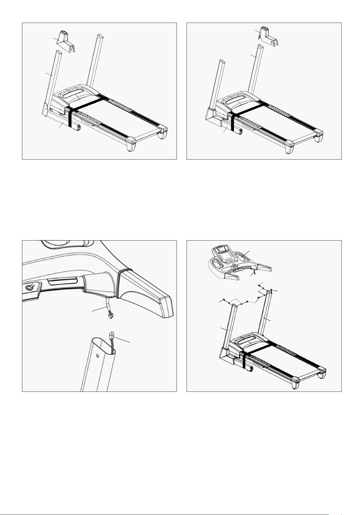
STEP 3
STEP 4
1. Insert the Left Upright Tube Cover (C08) into the bottom of the Left Upright Tube (A05).
Push down to secure the Left Upright Tube Cover (C08) to the Base Frame (A01).
2. Repeat the step above to attach the Right Upright Tube Cover (C09) to the Base Frame (A01).
1. Connect the Top Signal Wire (D04) to the Middle Signal Wire (D05).
2. Fix the Console (E) to the Left and Right Upright Tubes (A05 & A06) with 4 Bolts (D50) and
4 Lock Washers (D64). Tighten using Allen Wrench (B12).
C08
A05
A01
C09
A06
A01
D05
D04
E
D04
D64
D64
D50
D50
D50
A05
A06
10
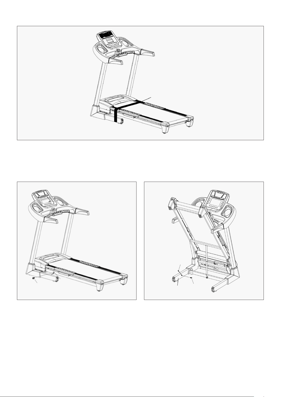
STEP 6
STEP 5
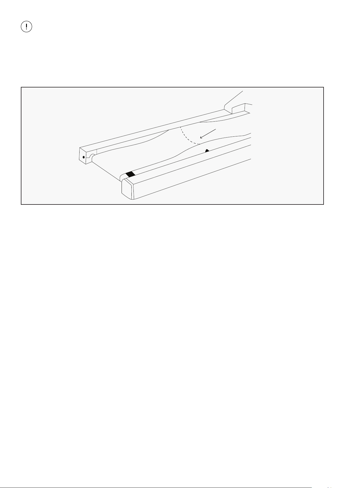
1. Cut the Packing Belt (F).
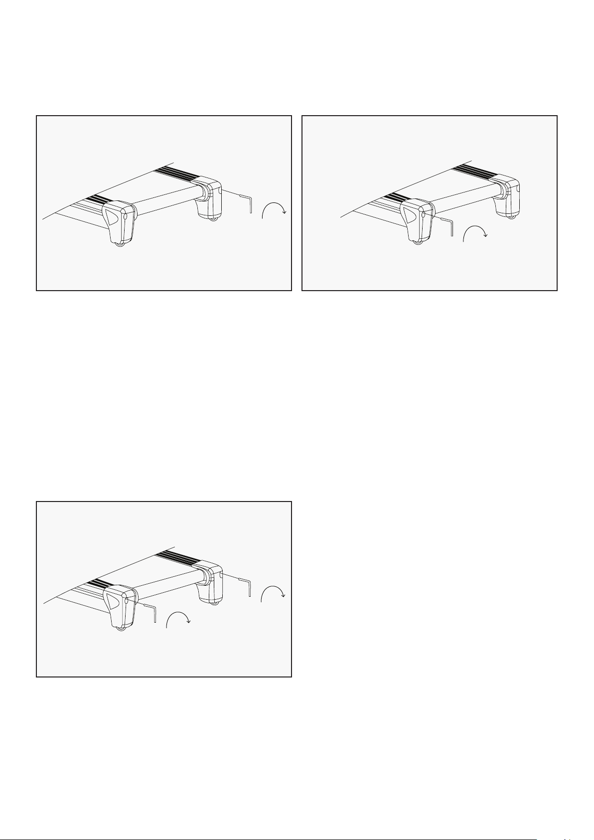
1. Loosen the M8*15 bolt (D50) in the main frame by using Allen Wrench (B12).
2. According to folding instruction, fold the machine, and loosen the M8*15 bolt (D50) in base
frame by using Allen Wrench (B12) then untie safety lock (No.B15)
| ASSEMBLY INSTRUCTIONS
F
D50
B15
B15
A01
D50
11
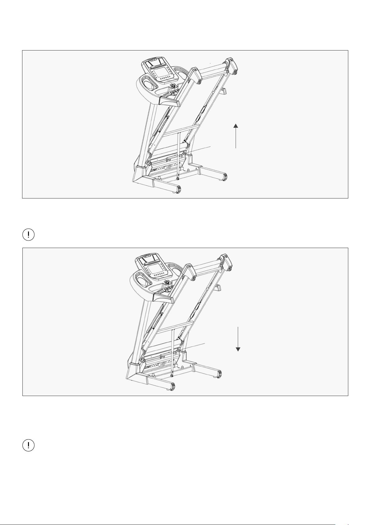
V. FOLDING INSTRUCTIONS
Place your hand at the end of the running deck (position K) and lift up the Main Frame until the Air
Pressure Cylinder (B03) locks.
FOLDING
Grasp the Main Frame with one hand (position K) and use your foot to lightly kick the Air Pressure
Cylinder (B03) to unlock. Give the Main Frame a downward push from position K and the running deck
should automatically continue to steadily lower itself until the Main Frame reaches level ground.
Video Tutorial Available at: http://youtu.be/TcuPbJ7KuxQ
Lifespan Fitness YouTube Channel: http://www.youtube.com/user/treadmillsvideos
UNFOLDING
FOLDING INSTRUCTIONS |
K
L
NOTE: You will hear a click when the Air Pressure Cylinder (B03) is successfully locked in.
NOTE: Before lowering the main frame, ensure that the space directly underneath it is clear
of any objects.
K
L
12
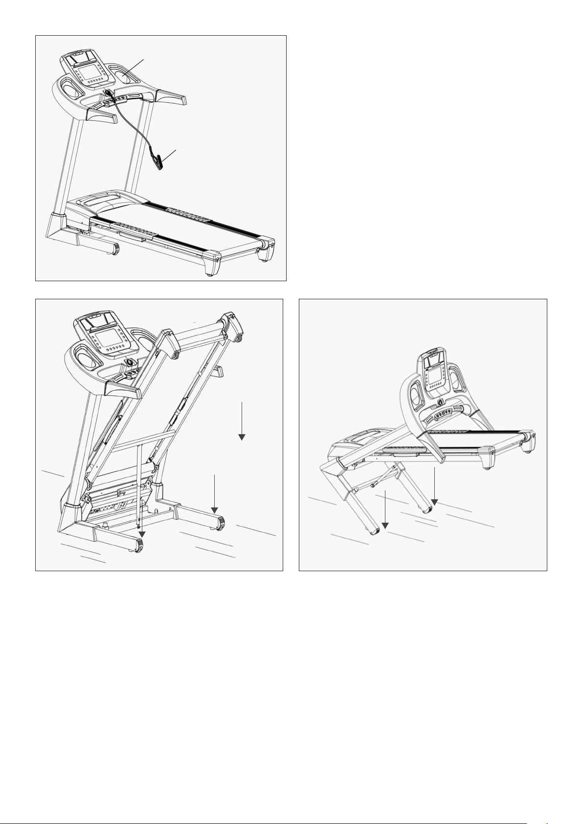
HOW TO USE THE SAFETY KEY
MOVING THE MACHINE
| FOLDING INSTRUCTIONS
E
C31
1. Before running, please insert the Safety
Key (C31) to Console (E) and clip the
opposing end to your clothes.
2. For any emergency, please pull the safety
key cord, the machine will stop immediately.
Before attempting to move the treadmill, please make sure the treadmill has been properly folded and
the power cord has been removed from the outlet.
Start by placing one hand at position K to support the top end of the treadmill. Next, place one foot at
position P to hold the bottom end of the treadmill steady.
With your foot at position P, slowly begin lowering the top of the treadmill towards the ground. Once the
top of the treadmill (position K) reaches a low enough point, the wheels will hit the ground, making it
easy to move your treadmill to the desired location.
K
P
P
P
K
P
13
VI. OPERATION GUIDE
OPERATION GUIDE |
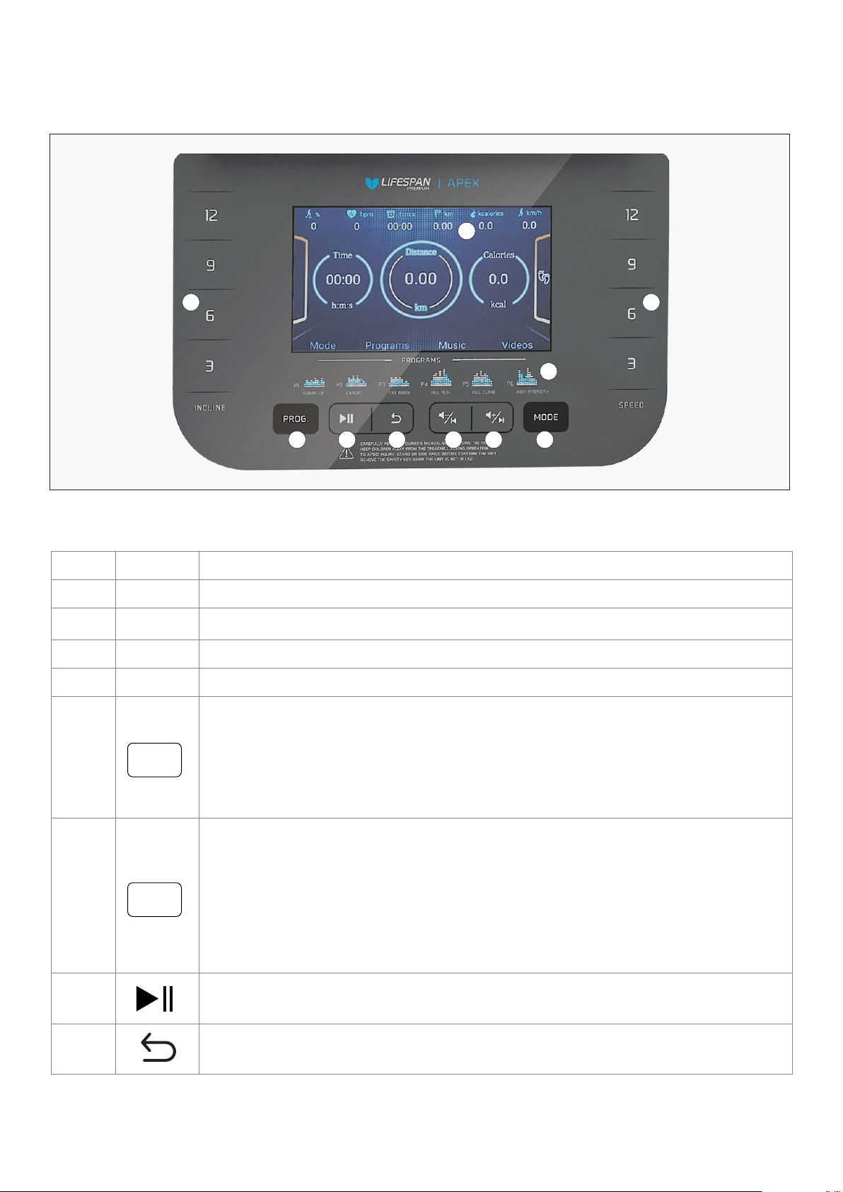
1. CONSOLE OVERLAY DISPLAY
1
2
3 4
5 67 8 9
10
NO. ICON FUNCTION INSTRUCTIONS
1 Parameter display
2 Program chart
3 "Incline: 3, 6, 9, 12": Incline shortcut button
4
"Speed: 3, 6, 9, 12": Speed shortcut button
5
"Program" button: Press the PROG key and the machine will show:
P1-P24: Preset Programs
U1-U3: User-Defined Programs
HP1-HP2: Heart Rate Control Programs (if applicable)
FAT: body fat test function
6
"Mode" button: Press this button to cycle through different countdown modes:
1. "15:00" flashing window is time countdown
2. "1.0" flashing window is distance countdown
3. "50" flashing window is calories countdown
4. Match Run mode
After you choose a mode, press "incline+" "incline –" or "speed+" "speed –" to set
countdown value. If you do not choose any mode, exit to back to standby mode.
7
Play/Pause button: To pause or to start when playing music or video.
8
Switch button: You can press this button to choose between standby mode,
music and video.
PROG
MODE
14 | OPERATION GUIDE
NO. ICON FUNCTION INSTRUCTIONS
9
VOL-/ DOWN button:
Long press: reduce volume. Short press: previous song.
10
VOL+/ UP button:
Long press: increase volume. Short press: next song.
11
12 1314
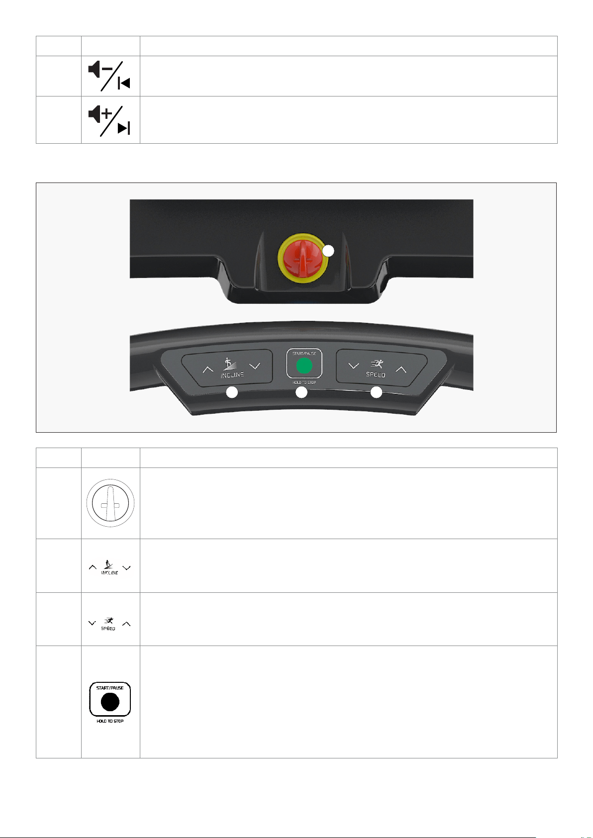
NO. ICON FUNCTION INSTRUCTIONS
11
Safety key: Insert the magnet end of the Safety Key into the slot of console. The
machine will not function until the safety key is inserted.
Remove the safety key in an emergency or after your workout to prevent unautho-
rized use.
12
"Incline+" "Incline-": In setting mode, press this button to adjust setting value.
When it is used to adjust incline, press and hold for more than 0.5 seconds, the
machine will increase or decrease incline by 1 level rapidly.
13
"Speed +" "Speed-": In setting mode, press this button to adjust setting value.
When it is used to adjust speed, press and hold for more than 0.5 seconds, the
machine will increase or reduce speed every 0.1 km rapidly.
14
"Start": To start the machine, insert the magnet end of the Safety Key into the slot
of console and press the START button.
"Pause": When the machine is running, press PAUSE button to pause
the machine.
Hold down START for 3 seconds to stop the machine and clear the workout. You
may also replace the safety key to reset the machine.
15OPERATION GUIDE |
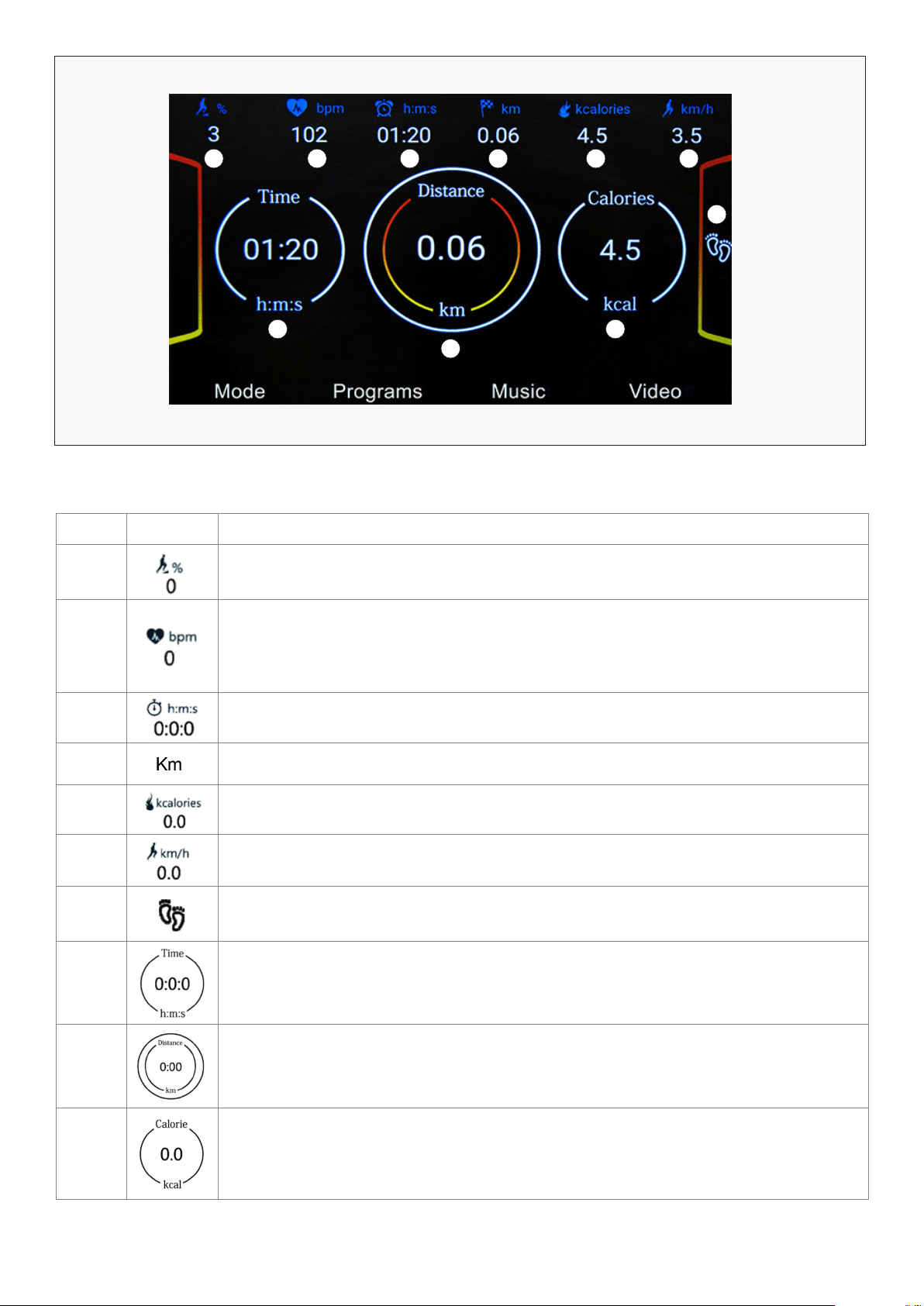
2. WINDOW DISPLAY
NO. ICON CONTROL INSTRUCTIONS
1 "INCLINE" window: Display the current incline. The Incline range is 0-18 level.
2
"PULSE" window: Hold the pulse sensors with both hands for 5 seconds to
calculate and display the runner’s heart beats per minute, the display range is
50-200 50-200 beats/min (This data is just for reference, and cannot be used as
the medical data).
3 "TIME" window: Display running time.
4
"DISTANCE" window: Display running distance.
5
"CALORIES" window: Display runner’s calories have burned.
6
"SPEED": Displays the current speed. The speed range is 1.0—20.0km/h.
7
"STEP": Calculate the runner’s steps when the runner is running on the machine.
8
"TIME" window: Display the running time.
9
"DISTANCE" window: Display the running distance.
10
"CALORIES" window: Display runner’s calories have burned.
1 2 3 4 5 6
7
8
9
10

16 | OPERATION GUIDE
3. MAIN FUNCTIONS
MATCH RUN MODE
CONTROL INSTRUCTIONS
"TIME" countdown window: Displays exercise time.
Displays the running time from 0:00-18 hours. When the count reaches the
maximum of 18 hours, the machine will reset to 0:00 and continue to operate.
When in Countdown Mode, it will count from the set time to 0:00. Once the count
reaches 0:00, the machine will stop smoothly and give a report.
"DISTANCE" countdown window: Displays exercise time.
Displays the running time from 0:00-18 hours. When the count reaches the
maximum of 18 hours, the machine will reset to 0:00 and continue to operate.
When in Countdown Mode, it will count from the set time to 0:00. Once the count
reaches 0:00, the machine will stop smoothly and give a report.
"CALORIES" countdown window: Display calories.
Displays the amount of calories burned from 0 to 999 KCAL. When the
count reaches 999, it will reset and start back from 0.
When in Countdown Mode, it will count down from the desired setting to 0. When
it reaches 0.00, the machine will stop smoothly and give a report.
MATCH RUN
MODE
You can choose this mode to have a running competition with system. Please find
below detailed explanation of how to use match running mode.
CONTEST DISTANCE (KM) Default time (min)
3km 18:00
5km 30:00
10km 01:00:00
15km
01:30:00
21.10km
02:06:35
42.19km
04:13:10
Press the "MODE" button continuously to enter match run mode. There are six default distances to
choose from:
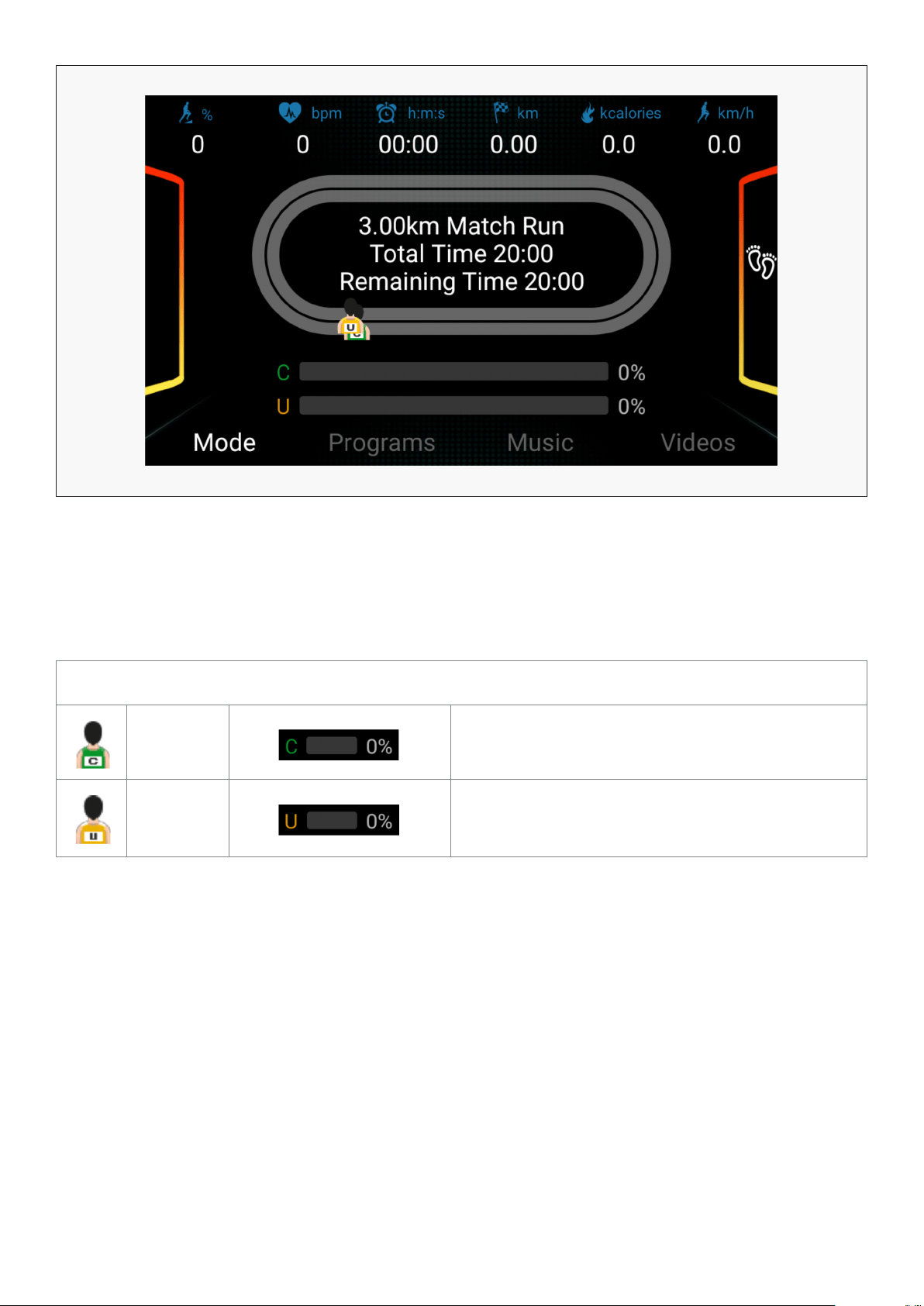
17OPERATION GUIDE |
After choosing distance, press the "INCLINE"+/- or "SPEED" +/- buttons to adjust the match time. Press
the START button to start.
During the process of the competition, you can press speed button to adjust speed, and press incline
button to adjust incline.
After the run is completed the system will judge your running performance automatically.
COMPETITION DISPLAY
C stands
for
computer
Displays the distance percentage competed by the
computer.
U stands
for user
Display the distance percentage competed by
the user.
18 | OPERATION GUIDE
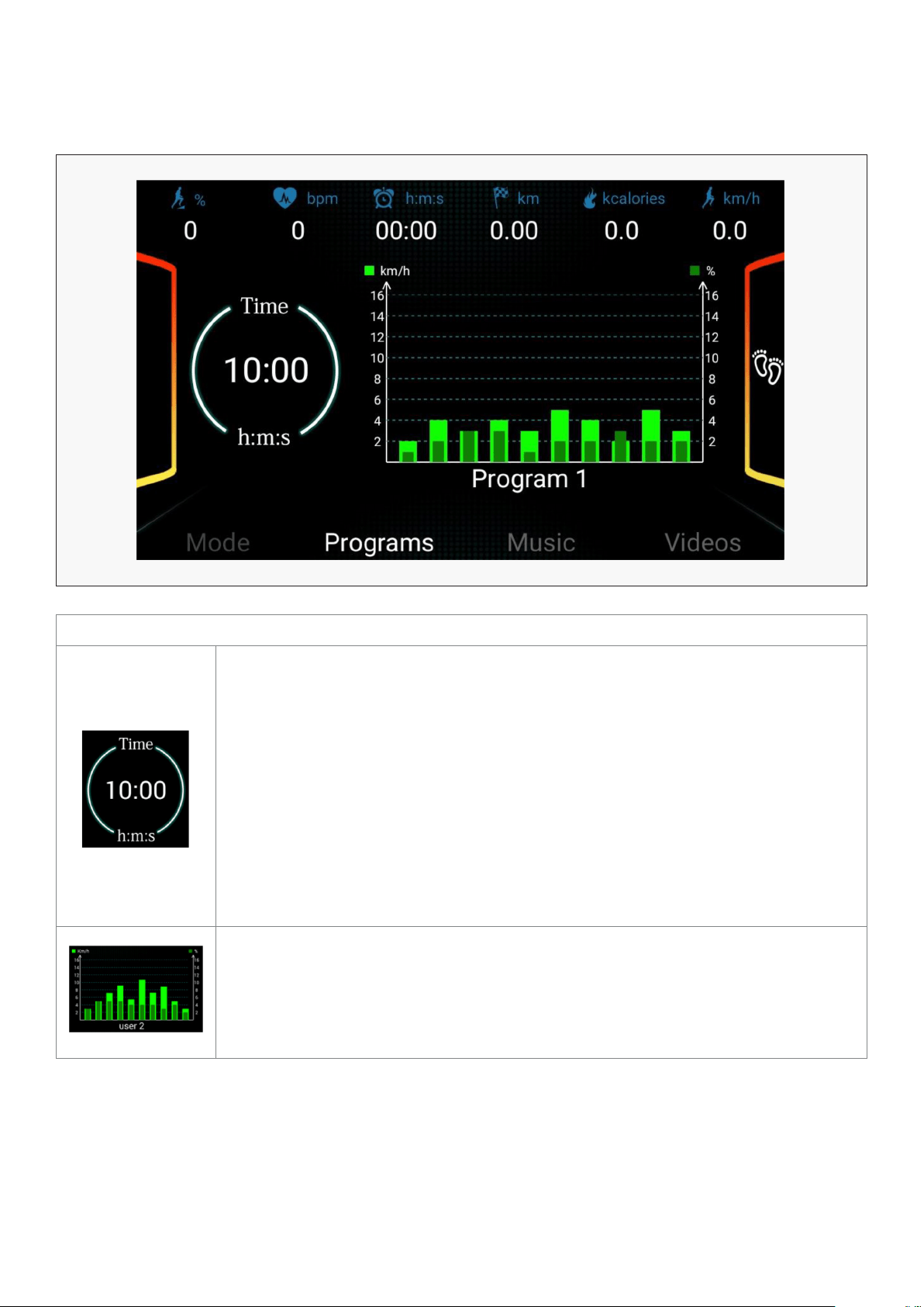
4. BUILT-IN PROGRAMS AND USER SETTING
4.1 BUILT-IN PROGRAMS
PROGRAM DISPLAY
Select the desired program, and the time window should display the setting time
at 10:00MINS. Press the +/– buttons to set the desired exercise time from 5MINS
to 99MINS.
Press the START button to start the program. When the system enters into the
next interval, the speed will be changed according to the program setting. Press
+/– keys to adjust the incline and speed. When the program enters the next
interval, it will return to the current incline and speed.
Each program will divide into 10 setting times for the exercise time, each time
section will adjust speed and incline accordingly depending on the speed and
incline determined within the program.
Program chart: Display 24 built-in programs, three user programs and the body
fat program.

19OPERATION GUIDE |
PROG TIME INTERVAL= SETTING TIME/10
1 2 3 4 5 6 7 8 9 10
P1
SPEED 2 4 3 4 3 5 4 2 5 3
INCLINE 1 2 3 3 1 2 2 3 2 2
P2
SPEED 2 5 4 6 4 6 4 2 4 2
INCLINE 1 2 3 3 2 2 3 4 2 2
P3
SPEED 2 5 4 5 4 5 4 2 3 2
INCLINE 1 2 2 3 1 2 2 2 2 1
P4
SPEED 3 6 7 5 8 5 9 6 4 3
INCLINE 2 2 3 3 2 2 4 6 2 2
P5
SPEED 3 6 7 5 8 6 7 6 4 3
INCLINE 1 2 4 3 2 2 4 5 2 1
P6
SPEED 2 8 6 4 5 9 7 5 4 3
INCLINE 2 2 6 2 3 4 2 2 2 1
P7
SPEED 2 6 7 4 4 7 4 2 4 2
INCLINE 4 5 6 6 9 9 10 12 6 3
P8
SPEED 2 4 6 8 7 8 6 2 3 2
INCLINE 3 5 4 4 3 4 4 3 3 2
P9
SPEED 2 4 5 5 6 5 6 3 3 2
INCLINE 3 5 3 4 2 3 4 2 3 2
P10
SPEED 2 3 5 3 3 5 3 6 3 3
INCLINE 4 4 3 6 7 8 8 6 3 3
P11
SPEED 2 5 8 10 6 9 5 3 2 2
INCLINE 1 3 5 8 10 7 6 3 2 3
P12
SPEED 2 5 5 4 4 6 4 2 3 4
INCLINE 3 5 6 7 12 9 11 11 6 3
P13
SPEED 2 7 4 7 8 9 4 5 3 2
INCLINE 5 6 6 4 6 5 8 9 4 2
P14
SPEED 2 6 5 4 8 6 5 2 3 3
INCLINE 5 6 5 8 4 5 5 10 6 3

20| OPERATION GUIDE
PROG TIME INTERVAL= SETTING TIME/10
1 2 3 4 5 6 7 8 9 10
P15
SPEED 2 6 5 4 8 7 5 3 3 2
INCLINE 3 4 5 6 3 5 5 6 4 3
P16
SPEED 2 5 7 5 8 6 5 2 4 2
INCLINE 1 5 6 8 12 9 10 9 5 3
P17
SPEED 2 5 6 7 8 9 10 5 3 4
INCLINE 3 5 6 8 6 5 8 7 5 3
P18
SPEED 2 3 5 6 8 6 9 6 5 2
INCLINE 5 7 5 8 6 5 9 10 6 2
P19
SPEED 3 7 6 5 9 7 6 3 5 2
INCLINE 3 5 6 8 5 6 5 12 8 3
P20
SPEED 3 7 9 10 11 12 10 8 5 2
INCLINE 2 5 6 7 6 5 8 6 3 2
P21
SPEED 3 6 8 7 9 10 5 8 3 2
INCLINE 3 6 8 9 9 6 8 10 6 3
P22
SPEED 3 5 8 6 9 10 8 12 6 3
INCLINE 2 6 8 10 12 10 12 8 5 2
P23
SPEED 3 5 9 11 12 8 6 5 3 2
INCLINE 2 6 8 10 9 7 8 10 6 3
P24
SPEED 3 8 10 11 12 10 10 8 5 3
INCLINE 3 6 8 9 10 12 9 6 3 2
21OPERATION GUIDE |
4.2 USER SETTINGS (U1-U3)
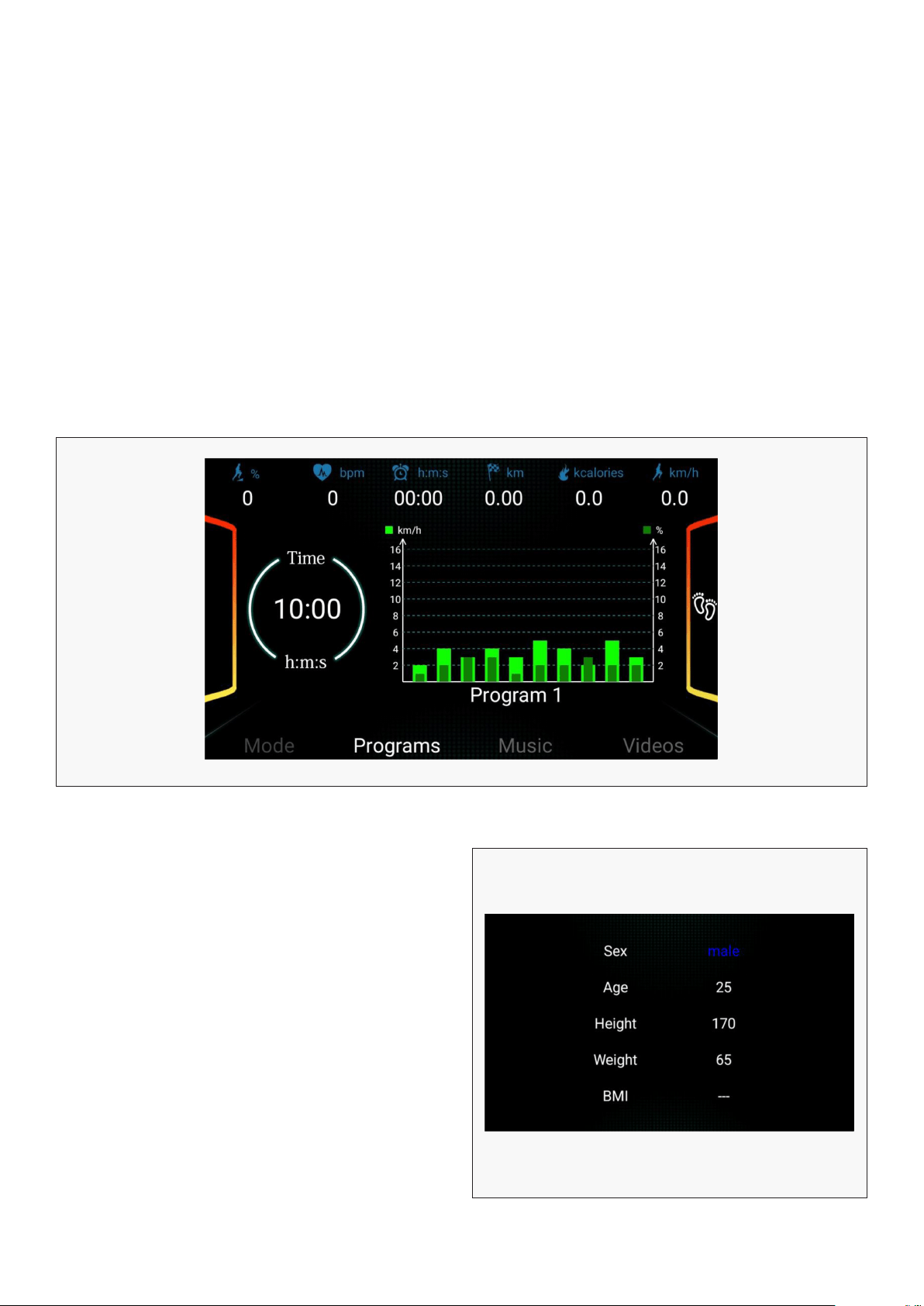
4.3 BODY FAT CALCULATOR
Press the PROGRAM button to cycle through the programs until you reach User1-User2-User3. User
Settings Programs (U1-U3) are programs that allow the user to manually preset each of the 10 exercise
programs in order to tailor your personal workout regime.
To begin, select U1 (first user setting profile), once you’ve select the setting, the TIME window will show
a setting time of 10:00MINS. Use the SPEED +/-, INCLINE +/-, or QUICK SPEED/INCLINE buttons to set
the desired value. Press the MODE key to move to next section or to skip through sections. Once you’ve
set the first section, you can set the value for the next section. Repeat this process until you have
completed all sections. The values you set will not change unless edited.
Once you have finished setting your workout regime, you may press the START button to begin
exercising. The machine will operate at the preset speed and incline of your settings. The whole program
will be divided into 10 sections. Each section will divide into 10 setting times for the exercise time,
and section will adjust to a speed and incline based on the speed and incline determined within the
program. When the whole program has completed, the machine will stop.
Press the PROGRAM button until the window
displays FAT (Body Fat Calculation). Press MODE to
enter SEX, AGE, HEIGHT, WEIGHT, BMI body quality
index.
Press the SPEED +/- keys to set SEX, AGE, HEIGHT,
WEIGHT (refer to the chart below). Once you have
finished setting, press MODE, this will take you to
the setup for BMI (Body Quality Index).
To set BMI, grasp the pulse sensors located on
the handles with both hands and hold them for at
least 3 seconds. The window will display your body
quality index. The Body Quality Index is used to
test the relation between your height and weight.
It is only for reference not suitable for the medical
use. The Body Quality Index is suitable for both
male and female.
22| OPERATION GUIDE
Sex Male
Female
Age 10-99 years old
Height 100-200 cm
Weight 20-150 kg
BQI ≤19 Underweight
BQI =(20---25) Normal Weight
BQI =(26---29) Overweight
BQI ≥30 Obesity
BODY QUALITY INDEX (BMI) CHART
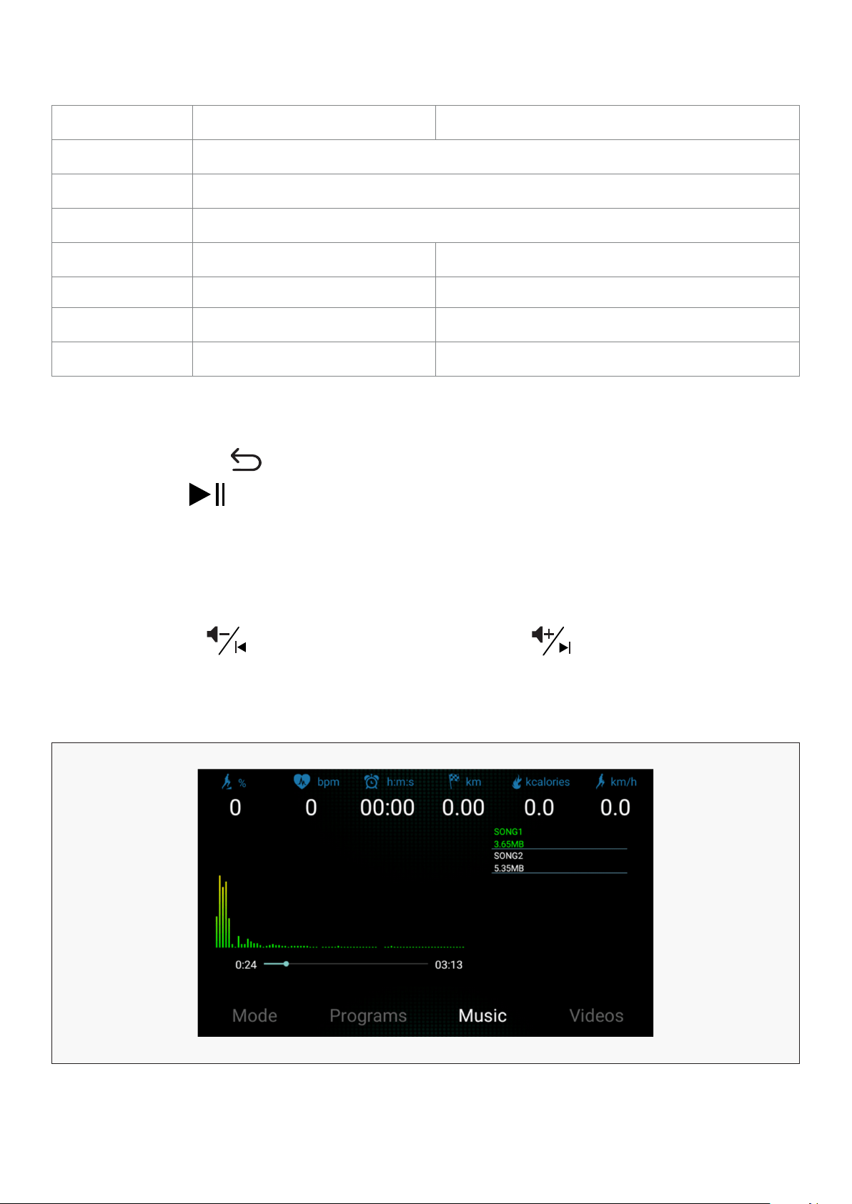
5. MUSIC
Press the switch button to enter music play function. WAV, MP3, MP4 formats are available. Then
press play button to play music.
Some system built-in music is available. You can also store music inside you own USB stick, and insert
it into the USB slot to play.
CONTROL GUIDE
VOL-/ DOWN button
VOL+/ UP button
- long press: reduce volume
- short press: previous song
- long press: increase volume
- short press: next song

23OPERATION GUIDE |
6. VIDEO
Press the switch button to enter video play function. RMVB, MOV, AVI formats are available. Then
press play button to play video.
Some system built-in video is available. You can also store videos inside you own USB stick, and insert
it into the USB slot to play.
CONTROL GUIDE
VOL-/ DOWN button
VOL+/ UP button
- long press: reduce volume
- short press: previous video
- long press: increase volume
- short press: next video
7. SPEAKER FUNCTION
Plug your phone or music player into the display via the AUX cable provided to play sound out of the
treadmill speakers. All volume and other functions will be controlled directly via your phone or music
player.
8. CONTROL FUNCTIONS
1. – Speed Button: reduce running speed.
2. + Speed Button: increase running speed.
3. – Incline Button: reduce incline.
4. + Incline Button: increase incline.
5. Speed Keys: instantly change speed.
6. Incline Keys: instantly change incline.
7. STOP: to stop the running belt of the machine.
8. Hold the pulse sensors with both hands for 5 seconds to calculate and display the runner’s
heart beats per minute (BPM) on the computer display screen.

24 | OPERATION GUIDE
9. QUICK START
10. LUBRICATION REMINDER
11. PLAYING MUSIC
1. Insert the magnet end of the safety key into the computer console.
2. Press the START button, a buzzer will sound and the system will automatically display a 3 second
countdown. When the countdown reaches zero, the running belt will start at a slow speed.
3. After start-up, you can use the speed +/– buttons or QUICK SPEED keys to adjust the speed of the
treadmill. You can also use the incline +/– buttons or QUICK INCLINE buttons to adjust the incline
of the treadmill.
The system will remind you to lubricate your treadmill every 300 kilometres via a warning on the
window. Please read the MAINTENANCE INSTRUCTIONS for the proper steps to lubricating your machine.
After lubrication is applied, press and hold the START/PAUSE button for 3 seconds to clear the reminder.
The window will then display total odometer distance.
To check the total distance: Press speed -, speed -, speed -, speed +, speed -, speed -, speed +, speed +,
speed +, speed +, speed - , and incline + in turn. This must be done within 5 seconds.
You can connect your mobile device to the treadmill to play music. To select music tracks and adjust
the volume of music, this will be done directly from your device buttons.
There are 2 ways to connect to the treadmill:
1. Connect your device using the MP3 AUX cable.
2. Connect your device using Bluetooth.
To connect using Bluetooth, make sure the MP3 AUX cable is disconnected. If the MP3 AUX cable is
connected, the Bluetooth will not function.
From your mobile device, select SYMK from the list of available devices and connect.
If the mobile device receives a phone call while it is connected using Bluetooth, the treadmill Bluetooth
will automatically disconnect. When you want to resume playing music on the treadmill, you will have
to connect again.
25
VII. EXERCISE GUIDE
PLEASE NOTE:
Before beginning any exercise program, consult your physician. This is important especially if you are
over the age of 45 or individuals with pre-existing health problems.
The pulse sensors are not medical devices. Various factors, including the user’s movement, may
affect the accuracy of heart rate readings. The pulse sensors are intended only as an exercise aid in
determining heart rate trends in general.
Exercising is great way to control your weight, improving your fitness and reduce the effect of aging and
stress. The key to success is to make exercise a regular and enjoyable part of your everyday life.
The condition of your heart and lungs and how efficient they are in delivering oxygen via your blood to
your muscles is an important factor to your fitness. Your muscles use this oxygen to provide enough
energy for daily activity. This is called aerobic activity. When you are fit, your heart will not have to work
so hard. It will pump a lot fewer times per minute, reducing the wear and tear of your heart.
So as you can see, the fitter you are, the healthier and greater you will feel.
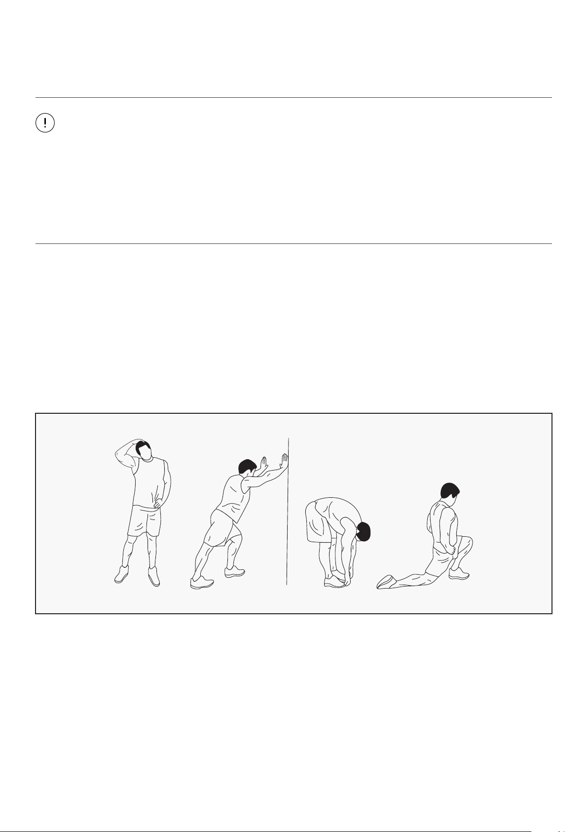
WARM UP
Start each workout with 5 to 10 minutes of stretching and some light exercises. A proper warm-up
increases your body temperature, heart rate and circulation in preparation for exercise. Ease into your
exercise.
After warming up, increase the intensity to your desired exercise program. Be sure to maintain your
intensity for maximum performance. Breathe regularly and deeply as you exercise.
EXERCISE GUIDE |
26
COOL DOWN
Finish each workout with a light jog or walk for at least 1 minute. Then complete 5 to 10 minutes of
stretching to cool down. This will increase the flexibility of your muscles and will help prevent post-
exercise problems.
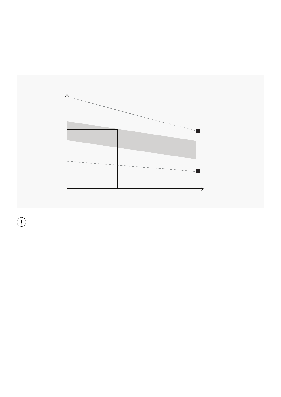
WORKOUT GUIDELINES
This is how your pulse should behave during general fitness exercise. Remember to warm up and
cool down for a few minutes.
TARGET ZONE
MAXIMUM
85%
70%
COOL DOWN
AGE
HEART RATE
200
180
160
140
120
100
80
20 25 30 35 40 45 50 55 60 65 70 75
The most important factor here is the amount of effort you put in. The harder and longer you work, the
more calories you will burn.
| EXERCISE GUIDE

27
VIII. MAINTENANCE INSTRUCTIONS
Reasonable cleaning/lubricating should be made to extend the lifetime of this unit. Performance is
maximized when the belt and mat are kept as clean as possible.
WARNING:
• The mat/deck friction may lay a major role in the function and life of your treadmill and that is why
we recommend you constantly lubricate this friction point to prolong the useful life of your treadmill.
Failing to do this may void your warranty.
• Unplug power cord before maintenance.
• Stop treadmill before folding.
• Use a soft, damp cloth to wipe the edge of the belt and the area between the belt edge and frame. A
mild soap and water solution along with a nylon scrub brush will clean the top of the textured belt.
This task should be done once a month. Allow to dry before using.
• On a monthly basis, vacuum underneath your treadmill to prevent dust build up. Once a year, you
should remove the black motor shield and vacuum out dirt that may accumulate.
1. GENERAL CLEANING
• Check parts for wear before use.
• Pay particular attention to the fixing knobs and make sure they are tight.
• Always replace the mat if worn and any other defective parts.
• If in doubt do not use the treadmill and contact us.
2. GENERAL CARE
Take care to protect carpets and floor in case of leakages. This product is a machine that
contains moving parts which have been greased/lubricated and could leak.
MAINTENANCE INSTRUCTIONS |
The mat/deck friction may play a major role in the function and life of your treadmill and that is why we
recommend you constantly lubricate this friction point to prolong the useful life of your treadmill. You
should apply lubrication after approximately the first 30 hours of operation.
3. BELT/DECK/ROLLER LUBRICATION
28| MAINTENANCE INSTRUCTIONS
We recommend lubrication of the deck according to the following timetable:
• Light use (less than 3 hours per week) every 6 months.
• Medium use (3-5 hours a week) every 3 months.
• Heavy use (more than 5 hours per week) every 6-8 weeks.
See below procedures for lubricating:
1. Use a soft, dry cloth to wipe the area between the belt and deck.
2. Spread lubricant onto the inside surface of belt and deck evenly (make sure the machine is
turned off and power is disconnected).
3. Periodically lubricate the front and rear rollers to keep them at their peak performance. If
the treadmill belt/deck/roller is kept reasonably clean it is possible to expect over 1200 hours
before relubricating is necessary.
Video Tutorial Available at: http://youtu.be/cP9NtFHfWlc
Lifespan Fitness YouTube Channel: http://www.youtube.com/user/treadmillsvideos
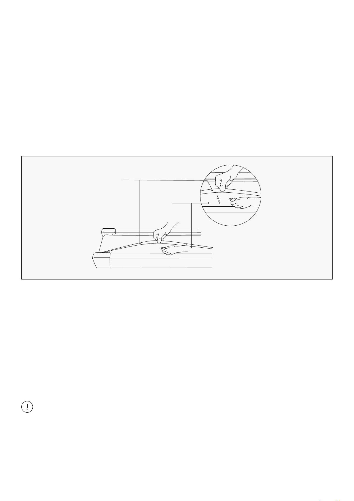
1. Disconnect the main power supply.
2. Fold the treadmill up into the storage position.
3. Feel the underside surface of the running mat.
If the surface is slick when touched, then no further lubrication is needed.
If the surface is dry to the touch, apply a suitable silicone lubricant.
4. HOW TO CHECK THE RUNNING MAT FOR PROPER LUBRICATION
Running
Belt
Board
We recommend that you use a silicone based spray to lubricate your treadmill.
This can be purchased directly from us or any hardware store.
Video Tutorial Available at: http://youtu.be/cP9NtFHfWlc
Lifespan Fitness YouTube Channel: http://www.youtube.com/user/treadmillsvideos
29MAINTENANCE INSTRUCTIONS |
C
To adjust the tightness of the belt: Turn the
treadmill off. Turn both the left and right
adjusting bolts 1/4 turn clockwise. Repeat until
the belt correctly tightens.
See Picture C
If the belt is over tightened, simply do the
opposite to loosen.
Place treadmill on a level surface. Run treadmill at approximately 4km/h, checking the running
condition.
5. ADJUSTING THE RUNNING BELT
If the belt has drifted to the right: Whilst the
treadmill is running at 4km/h, carefully turn
the right adjusting bolt 1/4 turn clockwise. Then
monitor treadmill until the belt centers. Repeat
until the belt correctly centers.
See Picture A
If you have over adjusted the belt and it drifts
to the right, carefully turn the right adjusting
bolt anticlockwiseuntil the belt centers.
A
If the belt has drifted to the left: Whilst the
treadmill is running at 4km/h, carefully turn
the left adjusting bolt 1/4 turn clockwise. Then
monitor treadmill until the belt centers. Repeat
until the belt correctly centers.
See Picture B
If you have over adjusted it, carefully turn the
left adjusting bolt anticlockwiseand until the
belt centers.
B
30
NOTE:
When properly tightened,you should be able to peel the very edge of the side of the belt up
approximately 2 inches. However, this is a rough reference and not all treadmills are the same.
Some treadmills that have longer belts may give different measurements for correct belt tightness.
Simply, if the belt begins to slip during use, this is an indication that the belt still needs tightening.
Video Tutorial Available at: http://youtu.be/vllsamTSvvA
Lifespan Fitness YouTube Channel: http://www.youtube.com/user/treadmillsvideos
| MAINTENANCE INSTRUCTIONS
31
IX. REPLACING MOTOR BRUSHES
After extended use, the motor brushes in your treadmill motor will wear down, and this can lead to
motor failure. It is important that you maintain your motor by replacing the brushes on either side of
the motor when they are worn down. We recommend that you check your motor every 1000 hours of
usage.
IMPORTANT:
Before beginning the replacement of your motor brush, ensure that the treadmill is off and unplugged
from the electrical socket.
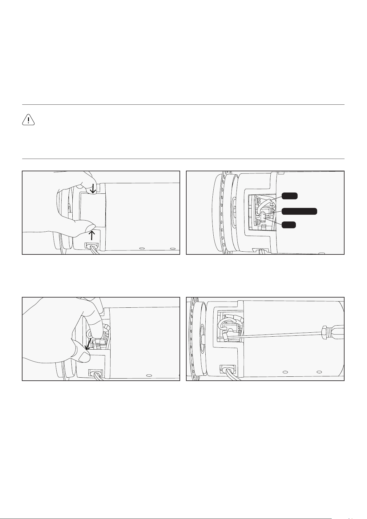
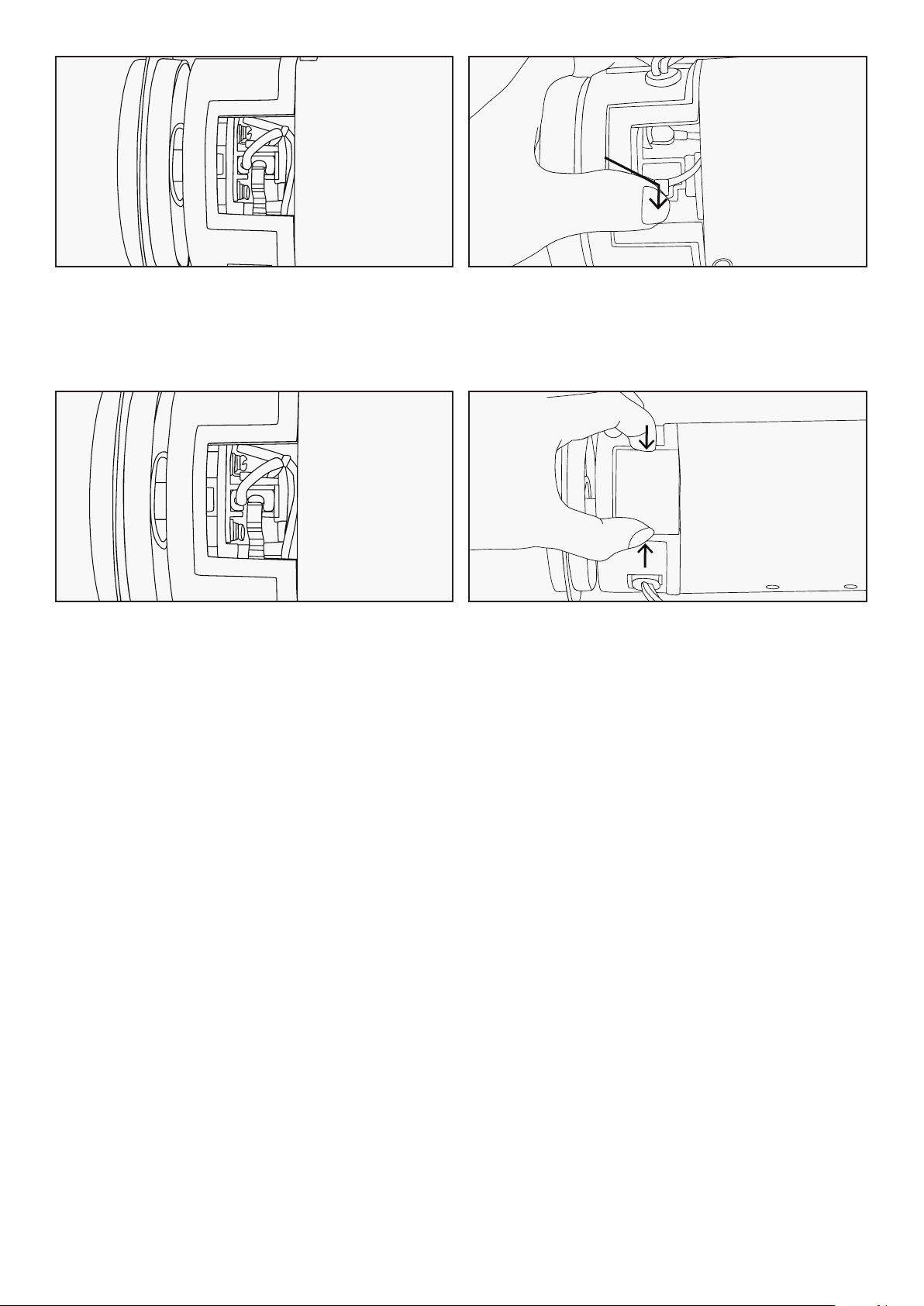
1. Remove the cover from the motor by
squeezing it from the sides.
2. You will find the motor brush held in with a
clip, with the lead plugged in.
Lead
Motor Brush
Clip
3. Pull the clip out from its position. 4a. Hold the clip out of the way with a
screwdriver or similar object. Keep the
screwdriver in this position until step 9.
REPLACING MOTOR BRUSHES |
32
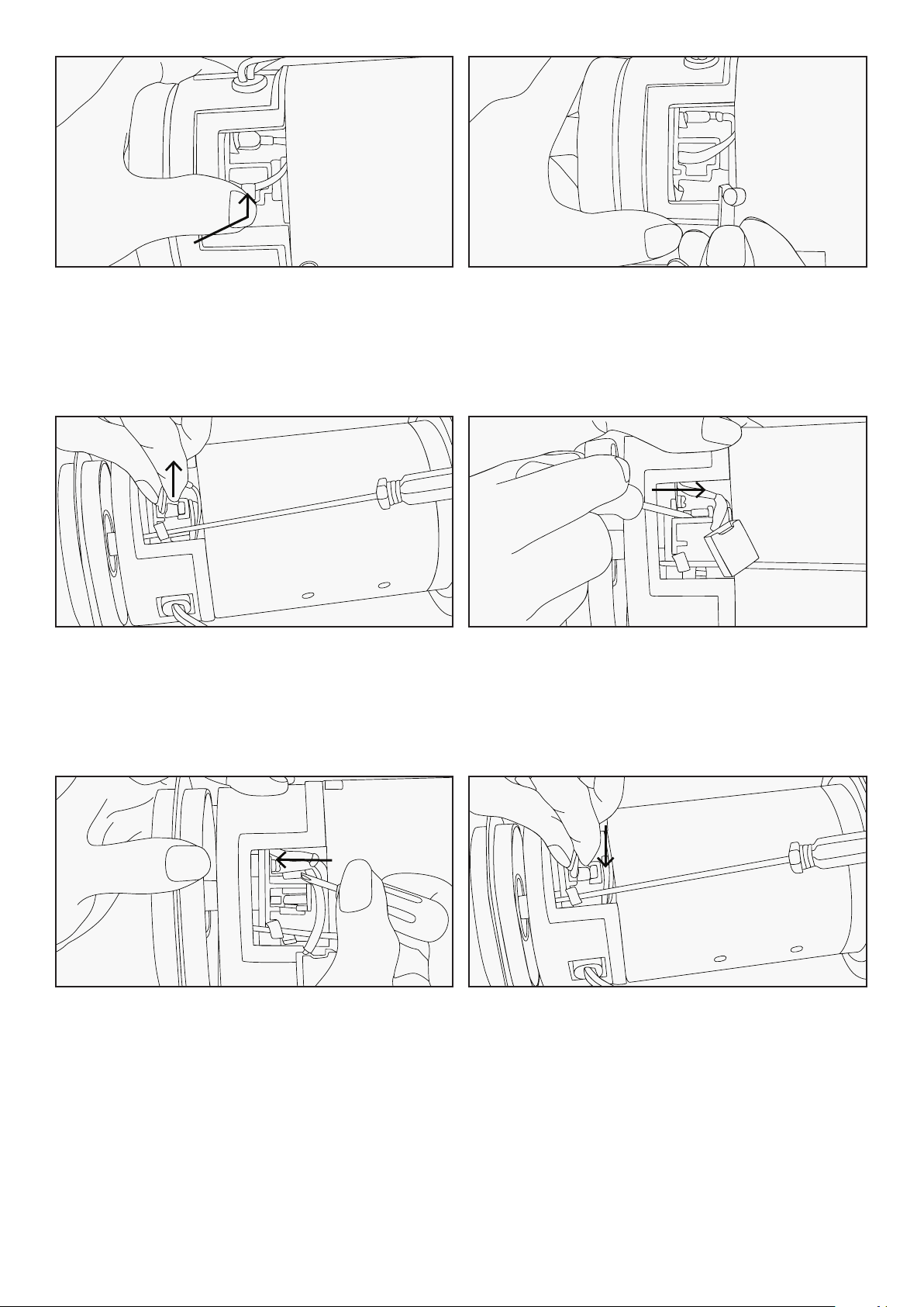
4b. Some treadmill motors may use a push
clip instead. In this case, gently push the
clip inwards and then up to release it from
its latch.
4c. Remove the clip, noting the direction in
which it was originally placed, and put it
safely aside.
5. Slide the motor brush out from its slot.
If the brush is shorter than 1cm on the
longest side, you will need to replace both
brushes.
6. Slide the motor brush lead off the terminal
using another small screwdriver or needle
nosed pliers.
7. Plug the new motor brush lead into the
terminal.
8. Slide the new motor brush into the slot.
| REPLACING MOTOR BRUSHES
33
9a. Release the clip back into its position. 9b. If your motor uses a push clip, replace the
push clip by pushing it inwards and then
down so that it engages the catch.
10. Check that the motor brush is held firmly
in place by the clip, and that the lead is
plugged securely onto the terminal.
11. Replace the motor cover. Repeat steps 1-15
for the second brush located on the
opposing side of the motor.
12. You have now successfully replaced the motor brushes. We also recommend that you remove any
dirt and dust from your treadmill motor fan using a vacuum cleaner before replacing the cover.
REPLACING MOTOR BRUSHES |
34
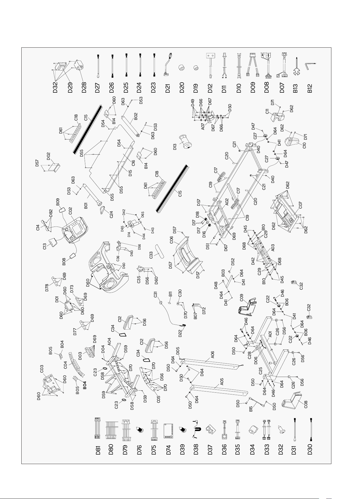
X. EXPLODED DIAGRAM
D60
D60
C04
D03
D77
D69
D69
D69
D60
D60
D60
D60
D69
C02
C24
D63
D60
D13
D49
D66
D67
D67
D66
D50
A07
B14
D61
C18
C15
C16
D15
D55
D54
D55
D53
B02
D53
D63
D60
B14
D54
C15
C18
D61
D55
C33
D57
C06
D57
D57
B01
D63
D53
B09
D57
D02
D82
C14
C13
B08
D01
D73
C03
B05
B04
B05
B04
B04
D04
C23
C23
D58
D59
D70
D59
C34
C34
D70
D70
D56
C05
C12
C12
D56
C31
C35
D56
D60
C30
D70
B07
D72
B11
D22
D56
D05
D64
D64
D64
A06
A05
D64
D64
D64
D56
D56
D56
C26
C08
C26
C22
C22
D46
D46
D64
D64
D41
B06
B06
C26
A01
D46
D50
D46
C09
D41
D41
D64
D64
D42
D68
D67
D69
D51
D16
D17
D17
D18
D57
C19
C19
C17
A02
C17
C20
C20
D40
C21
C21
D45
C29
B10
D45
C32
D68
A03
C29
B10
D62
D62
D62
D47
D47
D41
D64
D64
D62
D71
C10
D62
D71
C11
B12
B13
D07
D08
D09
D10
D11
D12
D19
D20
D21
D23
D24
D25
D26
D27
D28
D29
D32
C27
C27
D40
C07
D48
B03
D52
D64
D50
D50
D50
D50
D50
D50
B15
C28
C25
D06
D58
D59
A04
D78
D65
C36
D60
D60
D56
D42
D14
D44
D43
D65
C32
D8
1
D8
0
D7
9
D7
6
D7
5
D7
4
D3
9
D3
8
D3
7
D3
6
D3
5
D3
4
D3
3
D3
2
D3
1
D3
0
| EXPLODED DIAGRAM

35
XI. PARTS LIST
No. Description Specs Qty
A01 Base frame 1
A02 Main frame 1
A03 Incline bracket 1
A04 Console bracket 1
A05 Left upright tube 1
A06 Right upright tube 1
A07 Motor bracket 1
B01 Front roller 1
B02 Back roller 1
B03 Air pressure cylinder 1
B04 Hand pulse sheet iron 1 2
B05 Hand pulse sheet iron 2 2
B06 Transport wheel cover 4
B07 Spring sheet 2
B08 Left speaker net 1
B09 Right speaker net 1
B10 Turning bush 4
B11 Copper sheet 1
B12 Allen wrench 5mm 1
B13 Spanner with screw driver
S=13,14,15
1
B14 Z shape board 2
B15 Safety block 1
C01 Console top cover 1
C02 Console middle top cover 1
C03
Console middle bottom cover
1
C04 Hand pulse top cover 1
C05 Hand pulse bottom cover 1
C06 Motor top cover 1
C07 Motor bottom cover 1
C08 Left upright tube cover 1
C09 Right upright tube cover 1
C10 Left back end cover 1
C11 Right back end cover 1
No. Description Specs Qty
C12
Handle bar foam
2
C13
Rubber pad
1
C14
Plastic bracket
1
C15
Side rail
2
C16
Running belt
1
C17
Air cushion
2
C18
Side rail anti-slip pad
2
C19
Black cushion
4
C20
Blue cushion
2
C21
Blue cushion
2
C22
Transport wheel
2
C23
Oval inner plug
2
C24
Motor belt
1
C25 Cone-shape cushion 1
C26 Flat foot pad 4
C27
Adjustable wheel
2
C28
Wire protector
2
C29
Plastic pad
4
C30
Safety key bracket
1
C31
Safety key
1
C32
Transport wheel plug
2
C33
Motor top cover acrylic
1
C34 Handle bar decoration ring 2
C35
Handle bar left cover
1
C36
Handle bar right cover
1
D01
Computer board
1
D02
Control board
1
D03 Handle bar button board 1
D04
Top signal wire
900mm 1
D05
Middle signal wire
1100mm 1
D06
Bottom signal wire
800mm 1
D07
Shortcut top wire
350mm 1
D08 Shortcut bottom wire 750mm 1
PARTS LIST |

36
No. Description Specs Qty
D09
Hand pulse top wire
150mm 1
D10
Hand pulse middle wire
650mm 2
D11 Hand pulse bottom wire 200mm 2
D12
Speed sensor
1000mm
1
D13
DC motor
1
D14
Incline motor
1
D15
Running board
1
D16
Overload protector
1
D17
Square switch
1
D18
Power socket
1
D19
Magnetic ring
1
D20
Magnetic core
1
D21
Power wire
1
D22
Safety key wire
450mm 1
D23 AC single wire 200mm 1
D24 AC single wire 350mm 1
D25
AC Single wire
200mm 2
D26
AC Single wire
350mm 1
D27
Grounding wire
350mm 1
D28
Filter
1
D29
Inductor
1
D30
Single wire 2
350mm 1
D31
Grounding wire
350mm 1
D32
Screw
ST4.2*12 2
D33
Amplifier wire
300mm 5
D34
USB board
450mm 1
D35
USB wire
250mm 1
D36
Speaker
6Ω5ω
250mm
2
D37
Volume +/- connecting wire
350mm 1
D38
MP3 connecting wire
φ3*φ12*
410
1
D39
Screw
ST2.9*8.0
16
D40
Nut
M6 2
D41
Nut
M8 6
D42
Nut
M10 6
D43
Bolt
M10*90 1
D44
Bolt
M10*45 1
D45
Bolt
M10*30 4
No. Description Specs Qty
D46
Bolt
M8*40 6
D47
Bolt
M8*40 2
D48
Bolt
M8*30 1
D49
Bolt
M8*20 4
D50
Bolt
M8*15 10
D51
Bolt
M8*40 2
D52
Bolt
M8*42 1
D53
Bolt
M6*55 3
D54
Bolt
M6*40 2
D55
Bolt
M6*25 6
D56
Bolt
M5*16 11
D57
Bolt
M5*8 9
D58
Screw
ST4.2*30 4
D59
Screw
ST4.2*20 6
D60
Screw
ST4.2*12 27
D61
Screw
ST4.2*15 6
D62
Screw
ST4.2*30 15
D63
Washer 6
3
D64
Washer 8
16
D65
Washer
10
2
D66
Washer
8 6
D67
Flat Washer C 8
7
D68
Flat Washer C
φ10*φ
26*2.0
8
D69
Screw
ST2.9*8 22
D70
Screw
ST3.5*10 20
D71
Bolt
M5*12 2
D72
Screw
ST2.9*4 4
D73
Button board
1
D74
Bluetooth board
1
D75
Bluetooth wire
300mm 1
D76
Screw
ST4.2*15
4
D77
Incline key board
1
D78
Speed key board
1
D79
Connecting wire
150mm 1
D80
Connecting wire
200mm 2
D81
Connecting wire
100mm 1
D82
Screw
ST2.6*8 3
| PARTS LIST

37
XIV. TROUBLESHOOTING
1. Communication Error, Display to Control Board or vice versa
a. Check/change connection wire
b. Change display
c. Change control board
2. No Speed Signal
a. Check/change speed sensor
b. Change control board
3. Stall Protection
a. Check motor wires
b. Check motor
c. Check control board
4. Incline Failure
a. Check incline motor wires
b. Check incline motor
c. Check control board
5. Current Overflow Protection
a. Decrease load
b. Change transmission
c. Change motor
6. Motor Failure
a. Check motor wires
b. Check motor
7. Current Overflow
a. Adjust control board potentiometer
b. Check transmission
c. Change motor
8. Display Communication Error
a. Check display wires
9. Exterior Voltage Overflow or Low
a. Check current net
b. Repair
TROUBLESHOOTING |

38
XIII. WARRANTY
| WARRANTY
AUSTRALIAN CONSUMER LAW
Many of our products come with a guarantee or warranty from the manufacturer. In addition, they come
with guarantees that cannot be excluded under the Australian Consumer Law. You are entitled to a
replacement or refund for a major failure and compensation for any other reasonably foreseeable loss
or damage.
You are entitled to have the goods repaired or replaced if the goods fail to be of acceptable quality and
the failure does not amount to a major failure. Full details of your consumer rights may be found at
www.consumerlaw.gov.au.
Please visit our website to view our full warranty terms and conditions:
http://www.lifespanfitness.com.au/warranty-repairs
WARRANTY AND SUPPORT
Any claim against this warranty must be made through your original place of purchase.
Proof of purchase is required before a warranty claim may be processed.
If you have purchased this product from the Official Lifespan Fitness website, please visit
https://lifespanfitness.com.au/warranty-form
For support outside of warranty, if you wish to purchase replacement parts or request a repair or
service, please visit https://lifespanfitness.com.au/warranty-form and fill in our Repair/Service
Request Form or Parts Purchase Form.
Scan this QR code with your device to go to lifespanfitness.com.au/warranty-form

39
XIV. HAND PULSE TECHNOLOGY
This product comes equipped with hand pulse sensors which are used to pick up tiny EKG/ECG signals
that run through the body when your heart beats. These electrical EKG/ECG signals are very small and
that they must be amplified 1000 times to make the signal useful for the computer to display your
pulse.
To ensure proper operation:
• The user must maintain good, consistent contact on all four sensors.
• The users skin cannot be too dry or too wet.
Other factors that could affect the reading:
• Change of grip on the sensors (during slow pace walking and up to running).
• Tightening of hand muscles will produce small electrical signal.
• Static electricity charges from the air or from walking on the treadmill.
EKG/ECG Sensors may filter through actual EKG/ECG signals and "Noise" factors that may affect the
reading. This will cause the pulse reading to be delayed and will take longer to update the display as the
heart rate changes. Too much noise will create an incorrect reading. Medical conditions or having no
electrical signal in the hands are other factors that may affect pulse readings as well.
These are limitations of hand pulse technology and even the most expensive systems (which can
cost upwards of $3,000) used in hospitals have the same problems. The difference is that a patient
in a hospital is not running on a treadmill. Hand pulse technology works well on stationary exercise
machines like bikes and even elliptical cross trainers but are not perfect on a treadmill. We offer
treadmills with a wireless heart rate receiver which may be a more accurate option.
To test if your hand pulse sensors are working up to specification, hold them while standing on the
sidestep rails, not walking, and see if the reading is more in line with what you would expect. This will
eliminate the movement and static electricity factors. If your hands are dry, then wet them slightly
(saliva works as a great conductor if this doesn’t bother you).
HAND PULSE TECHNOLOGY |

WWW.LIFESPANFITNESS.COM.AU