Loading ...
Loading ...
Loading ...
11
CONNECTION OF THE POWER SUPPLY CABLE
Important! This cooker must be connected to the electricity supply only by an au-
thorised person.
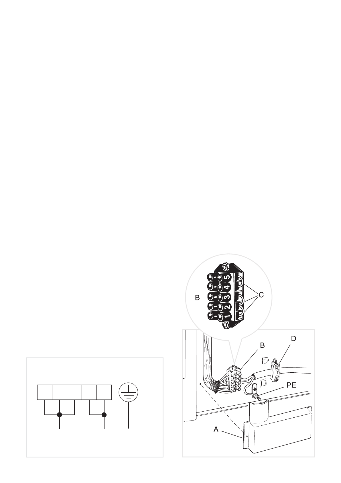
Remove the screws that hold shield “A
Fitted with a 5-pole terminal block, position the U bolts “C” onto terminal block “B”
Feed the supply cable through the cable clamp “D”. The supply cable must be of a
cable section”.
Connect the phase and neutral wires to the terminal block “B” and the earth wire to the
terminal “PE
Take up any slack in the cable and secure with the cable clamp “D”.
Replace the cover “A”.
N.B. The earth conductor must be left about 3 cm longer than the others.
VOLTAGE AND POWER CONSUMPTION
FEEDER CABLE SECTION
This cooker must be connected to electrical
supply using V105 insulated cable.
230-240 V~ 3 x 4 mm
2
(*)
(*) Connection with wall box connection.
– Diversity factor applied.
– A diversity factor may be applied to the to-
tal loading of the appliance only by a suita-
PE
12345
N (L
2
)L
1
230 V
230-240 V~
Figure 6
Figure 7
Loading ...
Loading ...
Loading ...