Loading ...
Loading ...
Loading ...
24
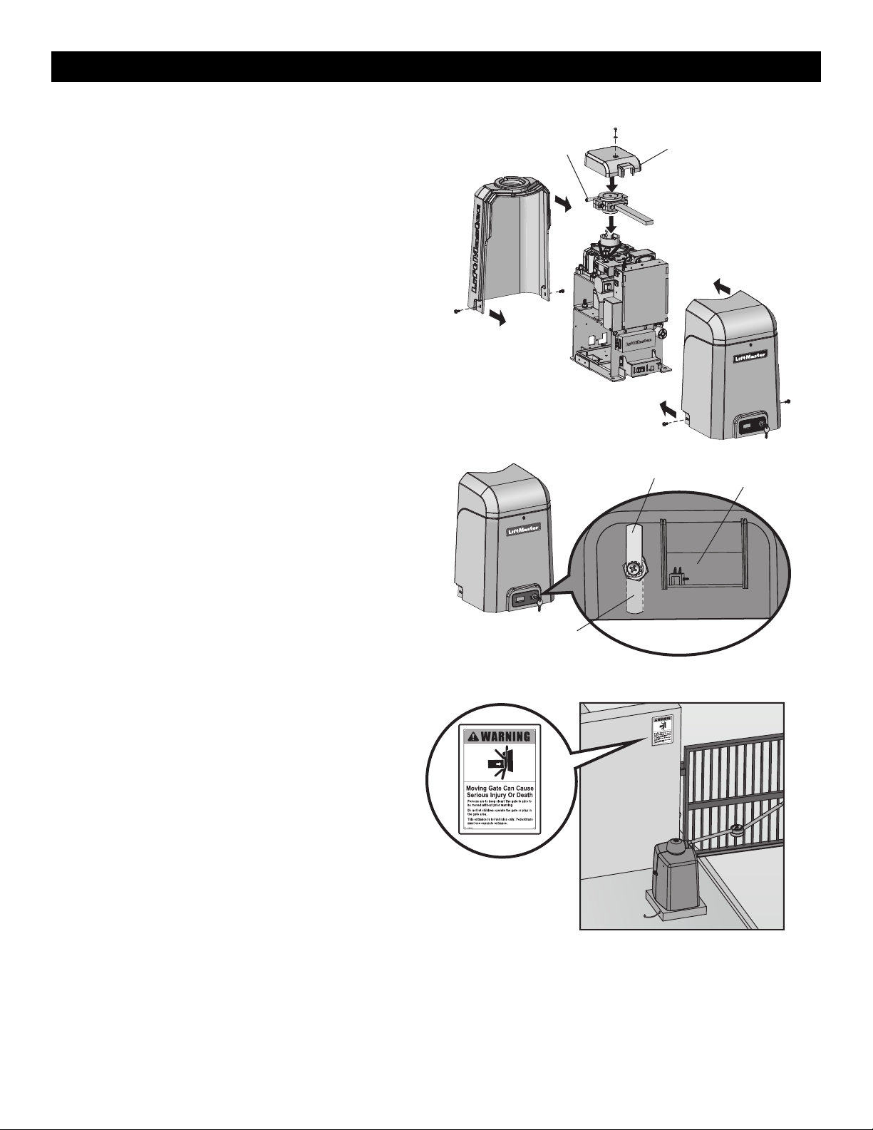
Step 11 Install the Cover
Before installing the cover, follow the instructions in the Adjustment
section to adjust the limits and force.
The operator cover consists of two pieces: a rear cover and a front cover.
The front cover can easily be removed to access the electrical box. Slide
the access door up to access the reset switch. The front cover and access
door can be locked with the key.
1. Remove the operator arm from the output shaft by releasing the
handle.
2. Place the rear cover over the operator.
3. Secure both sides of the rear cover to the chassis with the provided
screws.
4. Reattach the operator arm to the output shaft (making sure the pin
fits into the slot) and secure by pushing the handle down.
5. Place the top (cludge) cover over the operator arm and secure.
6. Align the front cover with the back cover and fit the front cover into
the grooves of the back cover.
7. Secure both sides of the front cover to the chassis with the provided
screws.
Manual Disconnect Handle Top (Cludge) Cover
To Lock the Access Door
From the factory the access door for the reset switch will not be locked.
To lock the access door follow the steps below:
1. Locate the lock tab on the back of the front cover and remove the
screw securing the tab to the cover.
2. Turn the tab 180 degrees, then secure with the screw. The access
door can now be locked.
(back of front cover)
Factory Default Position
Lock Tab
Access Door
Step 12 Install Warning Signs
Installers MUST install the UL required warning signs. The signs MUST
be installed in plain view on both sides of each gate installed. Use the
fastening holes in each corner to permanently secure the sign.
Place warning signs
on both sides of the
gate in clear view
The basic installation is complete.
INSTALLATION
Loading ...
Loading ...
Loading ...