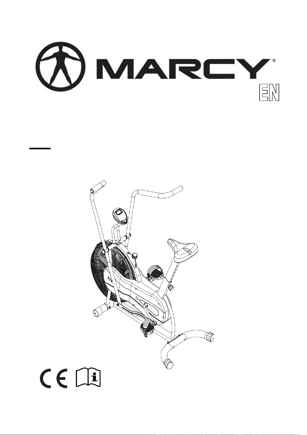
NS-BK1000
BK-1000
FAN BIKE
USER MANUAL
010817

2
CONTENTS
3
Important Safety Information
Weight Limit Capacities
Hardware Parts List 4
Pre Assembly CheckList 5
AssemblyInstructions 6 -11
Computer Instructions 12-13
ExerciseInstructions 13-14
Exploded Diagram 15
PartsList 16-17
ADDITIONALINFORMATION 18 - 19
Suppliedby:
Pure-Tec Limited
Tel: +44 (0) 1482 212098
Email:
service@puretecfitness.com
www.puretecfitness.com

3
IMPORTANT SAFETY INFORMATION
READ ALL INSTRUCTIONS BEFORE USING
1. This Bike is intended for class H (H=Domestic) use only. It is not designed for
commercialuse.
2. This machine has been tested to EN 957.
3. Read the OWNER’S OPERATIONMANUAL and all accompanying literature and follow it
carefully before using your Bike.
4. Keep children and pets away from the Bike at all times. Do not leave children
unattended in the same room with the Bike. The Bike is not a toy and therefore parents
and guardians should be aware of the natural tendency for children to play, leading to
situations and behaviour for which the Bike is not intended.
5. If children are allowed to use the Bike their physical/mental development and above all,
temperament should be taken into account. Constant supervision is therefore needed.
6. Position the Bike on a clear levelled surface which is clear of all obstacles as not to
restrict movement whilst exercising. DO NOT use the Bike near water or outdoors.
7. Exercise equipment has moving parts. In the interest of safety, keep others, especially
children, at a safe distance while exercising.
8. Never hold your breath while exercising. Breathing should remain at a normal rate in
conjunction with the level of exercise being performed.
9. Rest adequately between workouts. Muscle tone develops during these rest periods.
Beginners should work out twice a week and increase gradually to 4 to 5 times per
week.
10. Remove all jewellery, including rings, chains and pins before commencing exercise.
11.Always wear suitable clothing and footwear during exercise. Do not wear loose fitting
clothing that could become entangled with the moving parts of your exercise machine.
IMPORTANT!!! THE MAXIMUM RECOMMENDED WEIGHT CAPACITY FOR YOUR
BIKE IS 110KGS.
THIS OWNER’S MANUAL CONTAINS ASSEMBLY, OPERATION, MAINTENANCE AND
SAFETY INFORMATION. IN THE INTEREST OF SAFETY, PLEASE MAKE CERTAIN THAT
YOU READ AND UNDERSTAND ALL THE INFORMATIONBELOW.
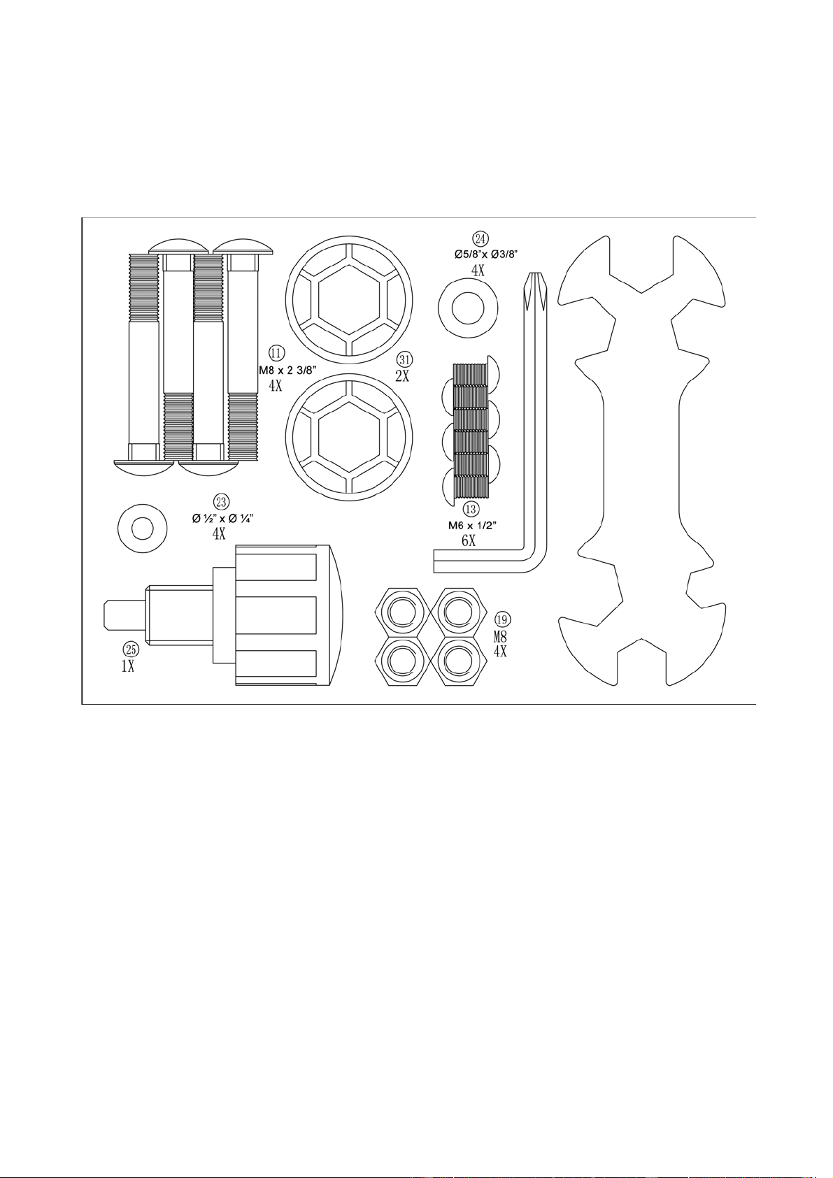
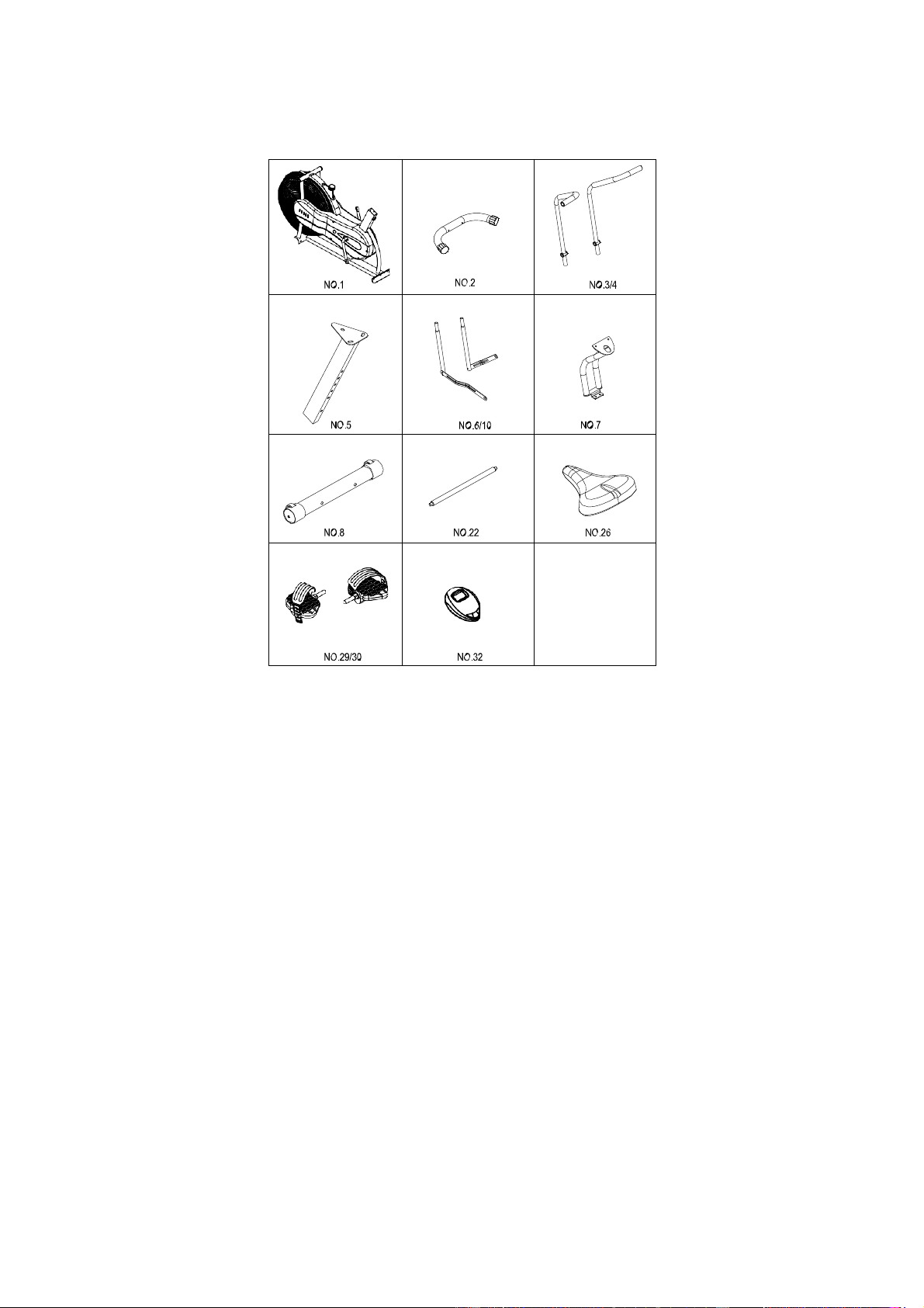
HARDWARE PACKING LIST
4
PRE-ASSEMBLY CHECK LIST
PART NO. DESCRIPTION Q’TY
1 Main frame 1
2 Rear Stabilizer 1
3 Left Handlebar 1
4 Right Handlebar 1
5 Seat Post 1
6 Lower Handlebar 2
10 ConnectingRod 2
7 ComputerPost 1
8 Front Stabilizer 1
22 Axle 1
26 Seat Pad 1
22 Axle 1
26 Seat Pad 1
29/30 Left/Right Pedal 1/1.
32 Computer 1
5
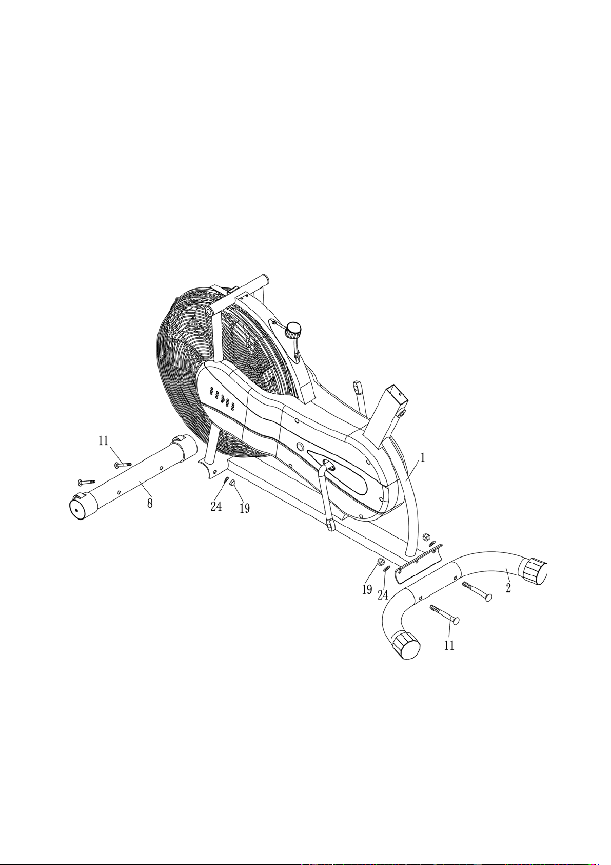
ASSEMBLY INSTRUCTION
STEP 1
Attach the Front Stabilizer (8) to the Main Frame (1). Secure it with two Carriage Bolts (11), two
Curved Washers (24), and two Domed Nuts (19).
Attach the Rear Stabilizer (2) to the Main Frame (1). Secure it with two Carriage Bolts (11), two
Curved Washers (24), and two Domed Nuts (19).
6
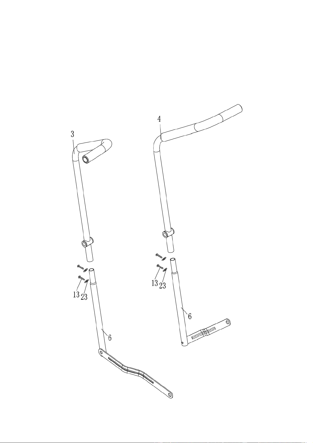
STEP 2
Insert the two Lower Handlebars (6) into Left & Right Handlebar (3 & 4) from bottom.
Secure each set of Handlebar with two Allen Bolts (13) and two Curved Washers (23). Do not
fasten the Bolts yet.
7
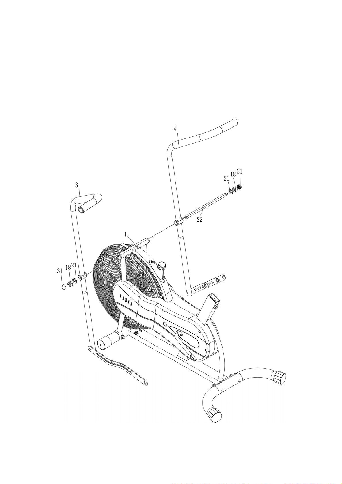
STEP 3
Remove the Flat Washer (21) and Aircraft Nut (18) from one end of theAxle (22).
Insert this open end of Axle through the pivot on Right Handlebar, pivot on Main Frame (1), and
through the pivot on Left Handlebar (3). Secure the open end of Axle with the Flat Washer (21)
and M10 Aircraft Nut (18) removed in procedureA.
Securely fasten Bolts and Nuts in Step-2 and Step-3. Cover the twoAircraft Nuts (18) by
two Cover Caps (31).
8
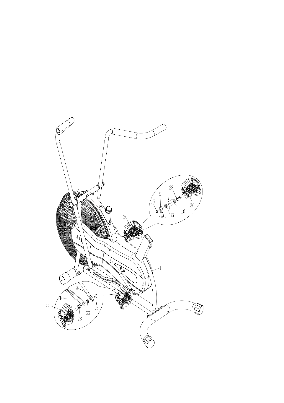
STEP 4
Slide one Spacer (28) onto the bolt on Left Pedal (29).
Plug one Bushing (33) into the hole on Connecting Rod (10) from the other side.
Insert the Left Pedal bolt through the hole on Connecting Rod and the Bushing.
Thread the end of Left Pedal bolt firmly into the Left Locking Nut (15) to securely hold the Left
Pedal in position.
Repeat procedure A through D to install the Right Pedal(30).
9
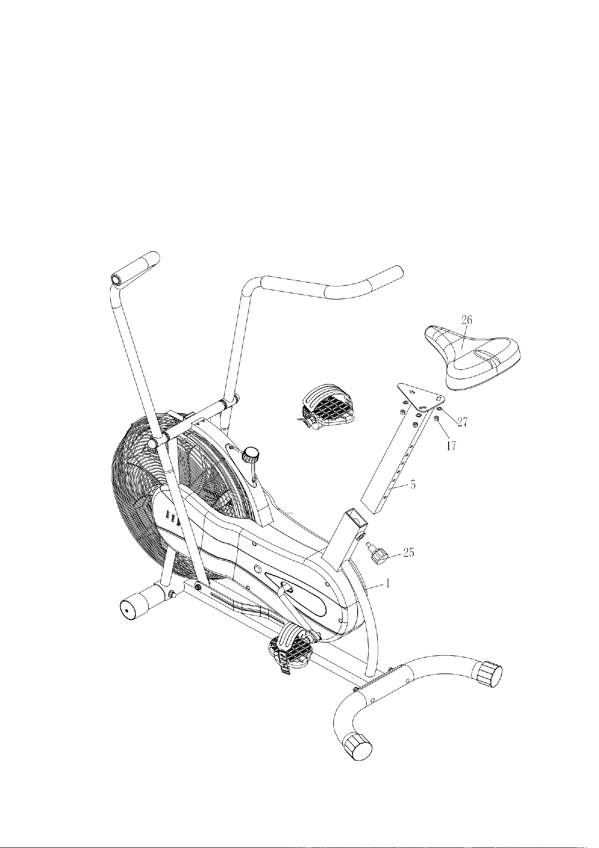
STEP 5
Remove the three Flat Washers (27) and three M8 Aircraft Nuts (17) from the Seat Pad (26).
Attach the Seat Pad (26) to the Seat Post (5). Securely fasten the Seat Pad to Seat Post with
the three Flat Washers (27) and three Aircraft Nuts (17).
Insert the Seat Post into the opening on Main Frame (1).Thread the Lock Knob (25) through the
selected hole on Seat Post to securely lock it at selected height.
10
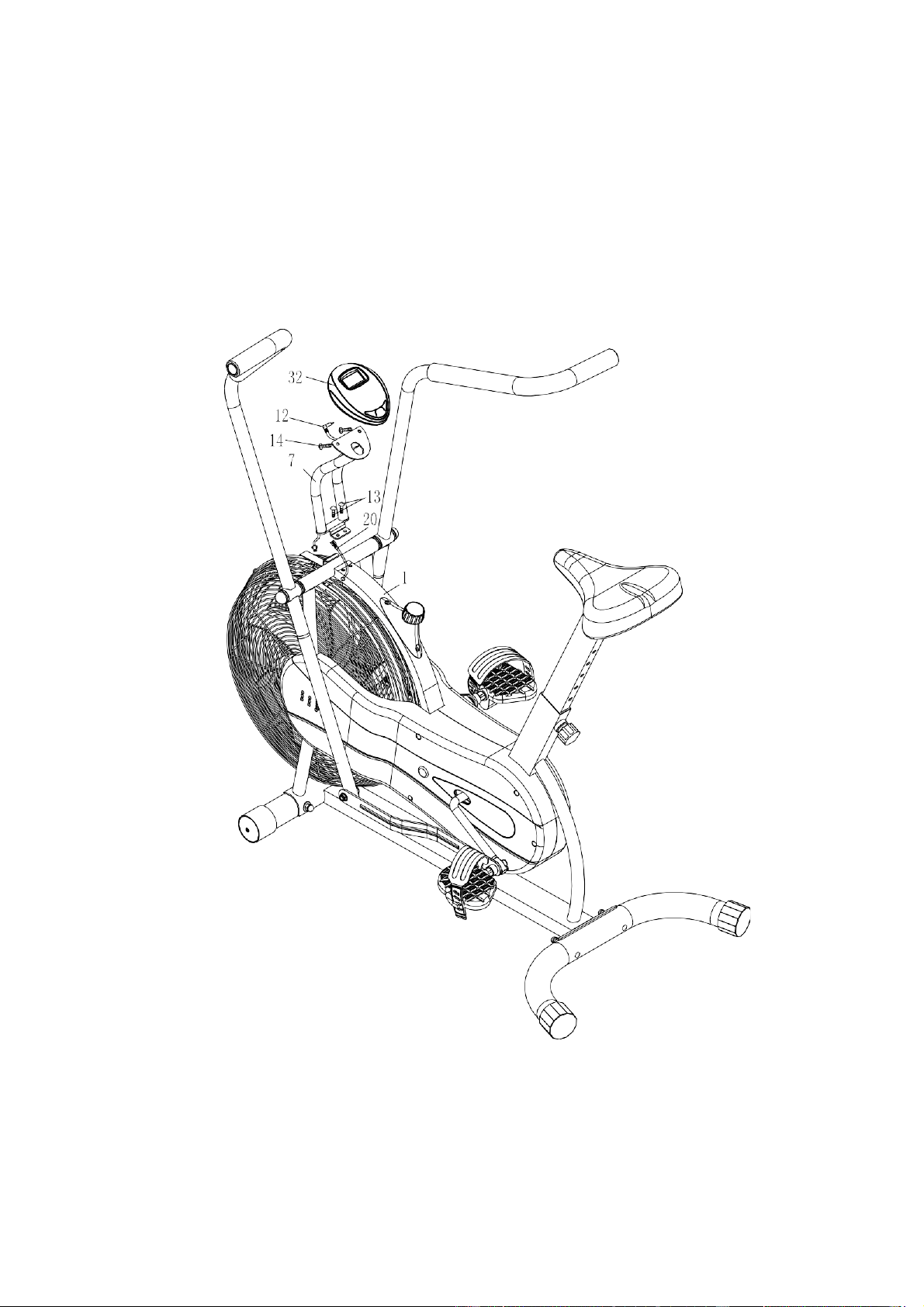
STEP 6
Attach the Computer Post (7) to Main Frame (1). Secure it with two Allen Bolts (13). Connect
the Lower Computer Wire (20) from Main Frame to the computer wire from Computer Post.
Remove the two Phillips Screws (14) from the Computer (32). Attach the Computer to
Computer Post. Secure it with the two Phillips Screws.
Connect the pin on the Upper Computer wire (12) from Computer Post to Computer.
CHECK ALL BOLTS AND NUTS ARE TIGHTENED
BEFORE USING THE MACHINE
11

COMPUTER INSTRUCTIONS
KEY FUNCTIONS:
MODE: This key lets you to select and lock on to a particular function you want.
SET(IF HAVE) :To set the values of time. distance and calories when not in scan mode.
RESET/CLEAR (IF HAVE): The key to reset the value to zero by pressing the key .
FUNCTIONS:
1.TIME : Press the MODE key until pointer lock in to TIME. The total working
time will be shown when starting exercise.
2.SPEED: P
ress the MODE key until pointer lock on to SPEED Display current
speed during working time .
3.DISTANCE:Pr
ess the MODE key until pointer lock on to DISTANCE . The
distance of each workout will be displayed when starting exercise.
4.CALORIE :P
ress the MODE key until pointer lock on to CALORIE The calorie
burned will be displayed when starting exercise.
5.ODOMETER(IF H
AVE): Automatically accumulates workout distance when starting
exercise.
6.RPM(IF H
AVE): Calculate the number of pulses per minute movement (lap) or steps.
7.PULSE(IF HAVE): Please press the MODE of health, switch to the" PULSE" function.
Through the heart rate sensor, measuring the number of beats per minute
8.SCAN : Display changes according to the next diagram every 4 seconds.
TIME---SPEED---DISTANCE---CALORIE---ODOMETER (IF HAVE) ---RPM
(IF HAVE)---PULSE (IF HAVE) ---SCAN
NOTE:
1.Without any signal coming in 4-5 minutes , the LCD display will be shut off automatically.
2.When there is signal input ,the monitor automatically turns on.
3.If there is a possibility to see an improper display on the monitor, please replace the
batteries to have a good result .You must be to replace the batteries at the same time.
4. Please ac
cording to the battery compartment labeled with battery.
5.If there is abnormal, please use the conductive metal in the power of the positive and
negativepole.
12
SPECIFICATIONS
TIME------------------------------------------------------------------------0:00~99:59MIN
SPEED---------------------------------------------------------------------0.0~999.9ML/H (KM/H)
DISTANCE----------------------------------------------------------------0.0~999.9ML (KM)
CALORIE-----------------------------------------------------------------0.0~999.9KCAL
ODOMETER (IF HAVE) ----------------------------------------------- 0~9999ML (KM)
PULSE (IF HAVE) ------------------------------------------------------40~240BPM
13
EXERCISE INSTRUCTIONS
Using your UPRIGHT BIKE will provide you with several benefits, it will improve your
physical fitness, tone muscle and in conjunction with a calorie controlled diet help you lose
weight.
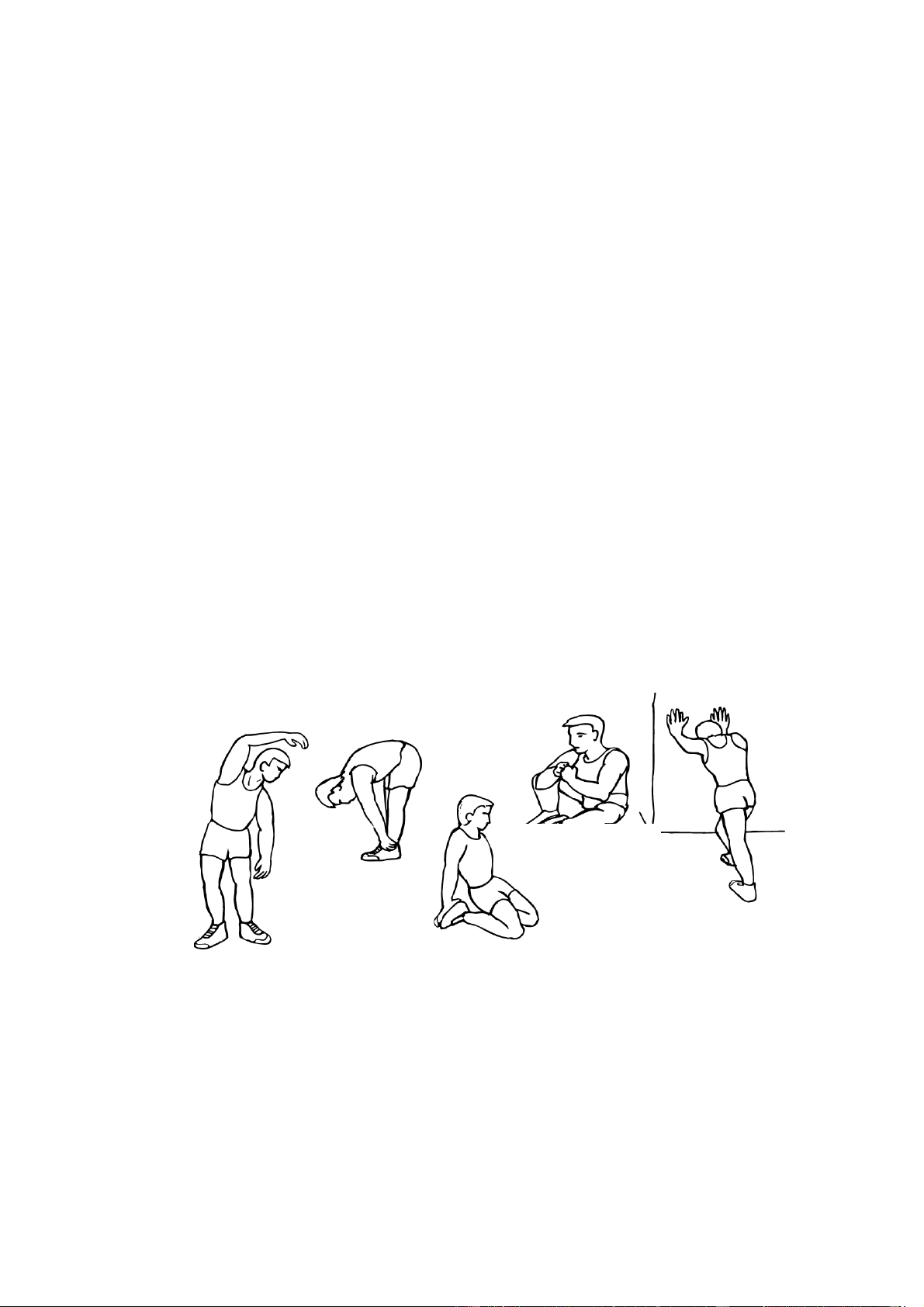
1. The Warm Up Phase
This stage helps get the blood flowing around the body and the muscles working properly. It
will also reduce the risk of cramp and muscle injury. It is advisable to do a few stretching
exercises as shown below. Each stretch should be held for approximately 30 seconds, do
not force or jerk your muscles into a stretch - if it hurts, STOP.
2. The Exercise Phase
This is the stage where you put the effort in. After regular use, the muscles in your legs will
become more flexible. Work to your but it is very important to maintain a steady tempo
throughout. The rate of work should be sufficient to raise your heart beat into the target
zone shown on the graph below.
SIDE BENDS
OUTERTHIGH
INNER THIGH
FORWARD
BENDS
CALF /ACHILLES
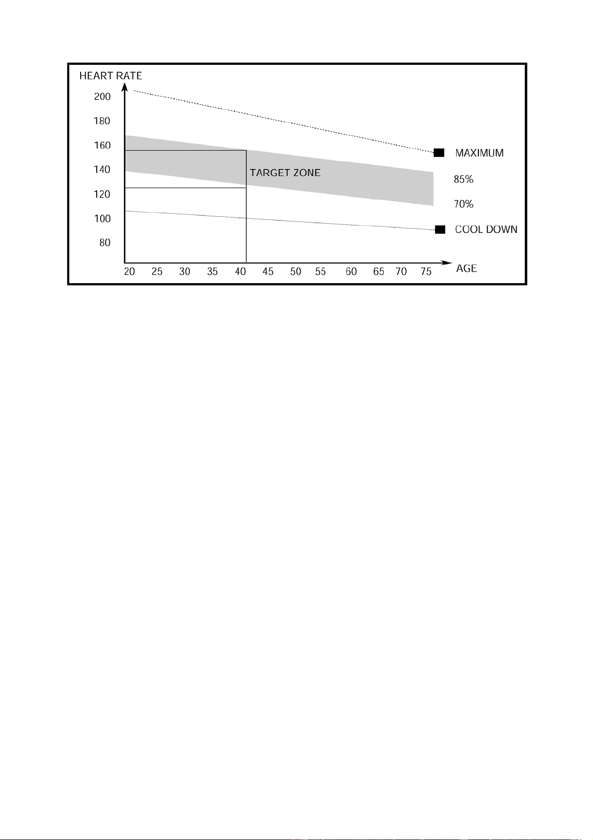
This stage should last for a minimum of 12 minutes though most people start at about 15-20
minutes
3. The Cool Down Phase
This stage is to let your Cardio-vascular System and muscles wind down. This is a repeat of
the warm up exercise e.g. reduce your tempo, continue for approximately 5 minutes. The
stretching exercises should now be repeated, again remembering not to force or jerk your
muscles into the stretch.
As you get fitter you may need to train longer and harder. It is advisable to train at least
three times a week, and if possible space your workouts evenly throughout the week.
MUSCLE TONING
To tone muscle while on your UPRIGHT BIKE you will need to have the resistance set quite
high. This will put more strain on our leg muscles and may mean you cannot train for as
long as you would like. If you are also trying to improve your fitness you need to alter your
training program. You should train as normal during the warm up and cool down phases,
but towards the end of the exercise phase you should increase resistance making your legs
work harder. You will have to reduce your speed to keep your heart rate in the target zone.
WEIGHT LOSS
The important factor here is the amount of effort you put in. The harder and longer
you work the more calories you will burn. Effectively this is the same as if you were
training to improve your fitness, the difference is the goal.
14
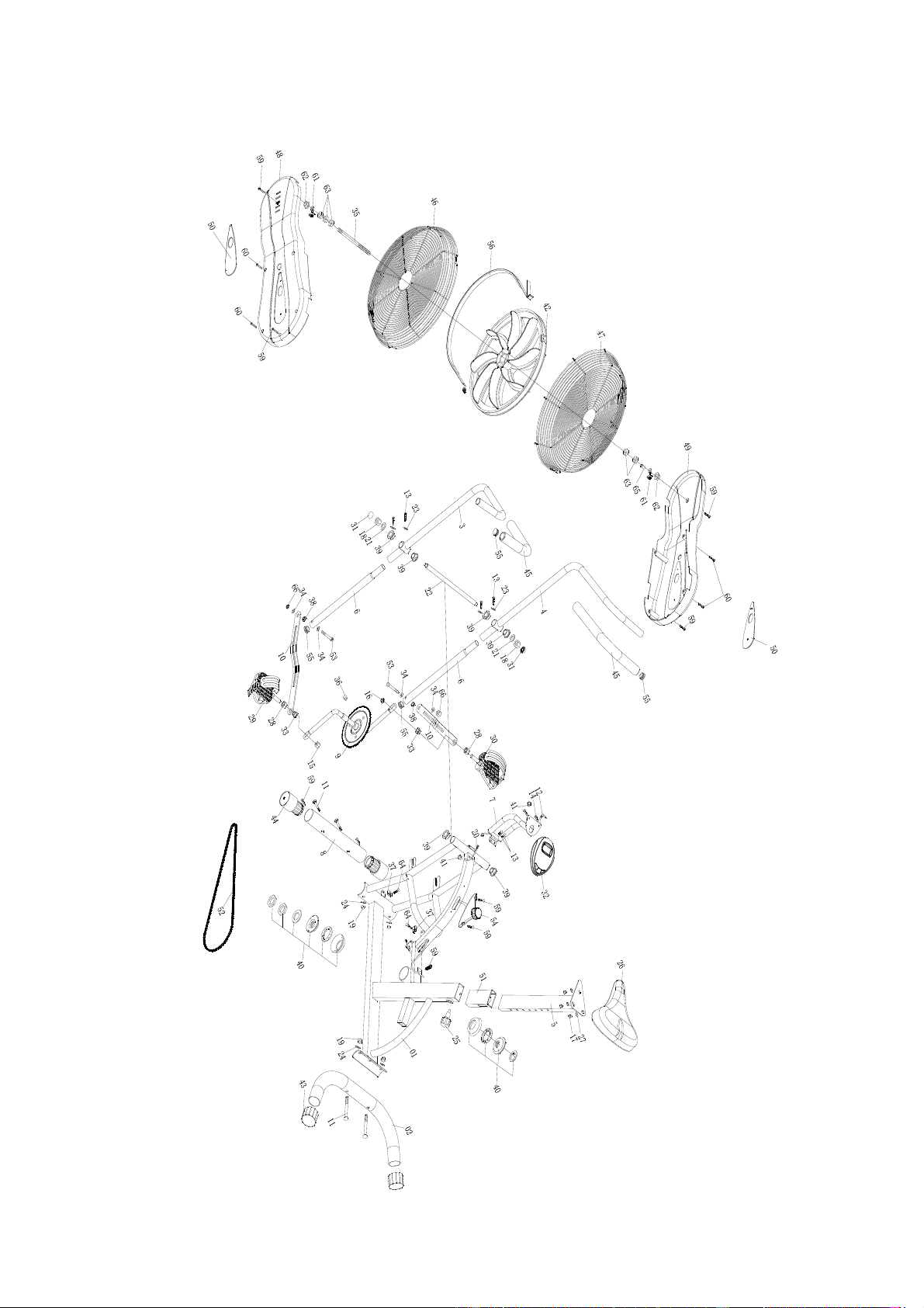
15
EXPLODED DIAGRAM

16
PARTS LIST
PART NO. DESCRIPTION QUANTITY
1 Main Frame 1
2 Rear Stabilizer 1
3 Left Handlebar 1
4 Right Handlebar 1
5 Seat Post 1
6 Lower Handlebar 2
7 ComputerPost 1
8 Front Stabilizer 1
9 Crank 1
10 ConnectingRod 2
11 CarriageBolt 4
12 Upper Computer Wire 1
13 AllenBolt 6
14 PhillipsScrew 2
15 Left LockingNut 1
16 Right LockingNut 1
17 AircraftNut 5
18 AircraftNut 2
19 DomedNut 4
20 Lower Computer Wire 1
21 Flat Washer 2
22 Axle 1
23 CurvedWasher 4
24 CurvedWasher 4
25 Lock Knob 1
26 Seat Pad 1
27 Flat Washer 3
28 Spacer 2
29 Left Pedal 1
30 Right Pedal 1
31 CoverCap 2
32 Computer 1
33 Bushing 2
34 Flat Washer 4
35 Sleeve 1
36 MagnetAssembly 1
37 SensorBracket 2
38 Powder Spacer 2
39 Plastic Spacer 6

17
PARTS LIST
PART NO. DESCRIPTION QUANTITY
40 BBAssembly 1
41 Grommet 2
42 Fan Wheel 1
43 End Cap For Rear Stabilizer 2
44 End Cap For Front Stabilizer 2
45 Foam Grip 2
46 Left Fan WheelCover 1
47 Right Fan WheelCover 1
48 Left Chain Cover 1
49 Right Chain Cover 1
50 DecoratingCover 2
51 Sleeve 1
52 Chain 1
53 Hex HeadBolt 2
54 TensionKnob 1
55 CirclePlug 4
56 Meshbelt 1
57 Wrench 2
58 AllenKey 1
59 Self-tappingScrew 7
60 Self-tappingScrew 4
61 Adjusting ScrewNut 2
62 FrangeNut 2
63 AllenNut 5
64 Self-tappingScrew 4
65 Sleeving 1
66 NylonNut 2

ADDITIONAL INFORMATION
Packaging Disposal
Government guidelines ask that we reduce the amount of waste material disposed of in
land fill sites. We therefore ask that you dispose of all packaging waste responsibly at
public recycling centres.
End of Life Disposal
We at Pure-Tec Limited hope you enjoy many years of enjoyable use from your Bike.
However, a time will come when your Bike will come to the end of its useful life. Under
‘European WEEE Legislation‘ you are responsible for the appropriate disposal of your
Bike to a recognised public collection facility.
CARE AND MAINTENANCE
1.Inspect and tighten all parts before using the Bike.
2.The Bike can be cleaned using a damp c
loth and mild non-abrasive detergent. DO
NOT usesolvents.
3. Examine the Bike regularly for signs of damage or wear.
4. Failure to examine the Bike regularly may affect the safety level of the equipment.
5. Replace any defective components immediately and/or keep the Bike out of use until
repair.
18

LIMITED WARRANTY
Pure-Tec. warrants this product to be free from defects in workmanship and material,
under normal use and service conditions. Please refer to www.puretecfitness.com for
warranty conditions. This warranty extends only to the original purchaser and is valid for
home use only. Pure-Tec’s obligation under this Warranty is limited to replacing
damaged or faulty parts at Pure-Tec’soption.
All returns must be pre-authorised by Pure-Tec. This warranty does not extend to any
product or damage to a product caused by or attributable to freight damage, abuse,
misuse, improper or abnormal usage, purchasers own repairs or for products used
for commercial or rental purposes. No other warranty beyond that specifically set forth
above is authorised by Pure-Tec.
Pure-Tec is not responsible or liable for indirect, special or consequential damages arising
out of or in connection with the use or performance of the product or other damages with
respect to any economic loss, loss of property, loss of revenues or profits, loss of
enjoyments or use, costs of removal, installation or other consequential damages or
whatsoevernatures.
The warranty extended hereunder is in lieu of any and all other warranties and any implied
warranties of merchantability or fitness for a particular purpose is limited in its scope and
duration to the terms set forth herein.
Your statutory rights are not affected.
ORDERING
REPLACEMENT PARTS
Replacement parts can be ordered by contacting our Customer Solutions
Department,
www.puretecfitness.com
Email: service@puretecfitness.com
When ordering replacement parts, please give the following information,
1. Model
2. Description of Parts
3. Part N
umber
4. Date of P
urchase
19