Owner Manual Battery Charger
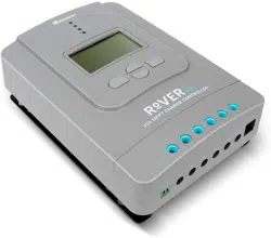
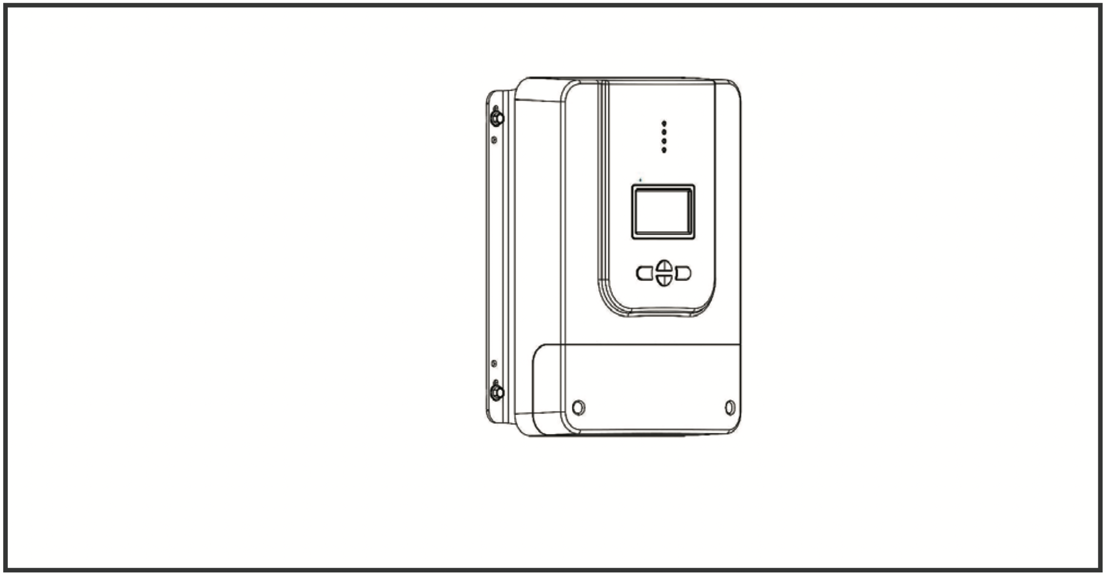
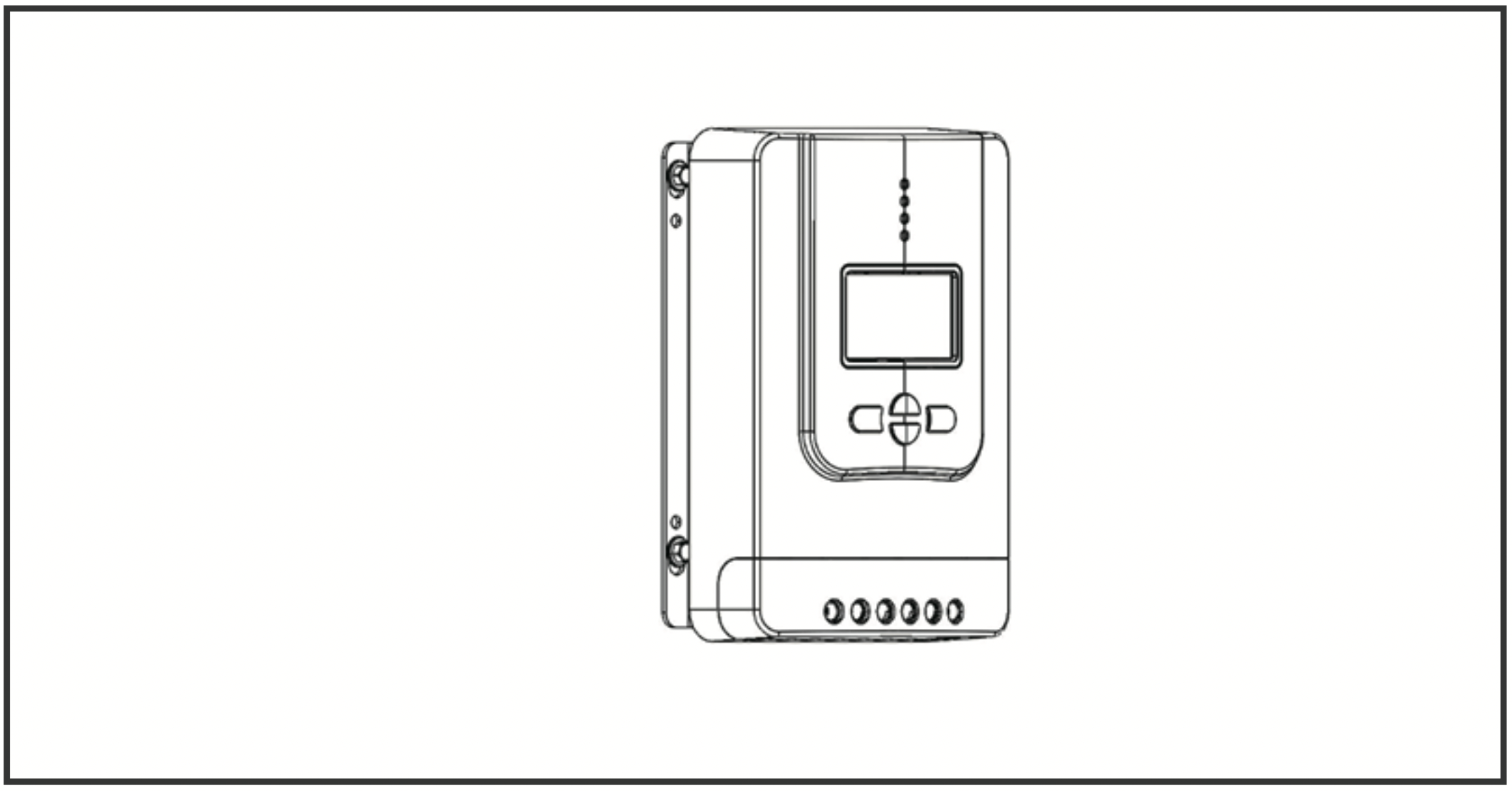
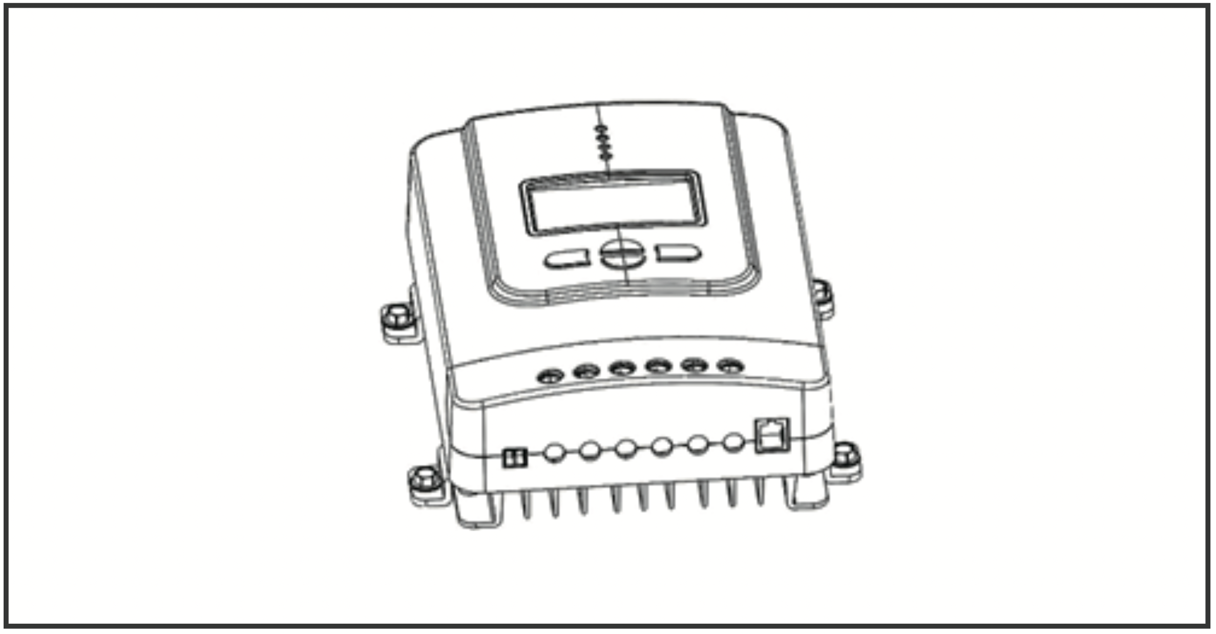
Identification of Parts
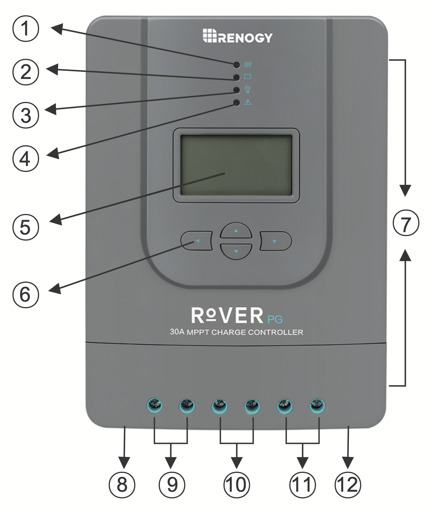
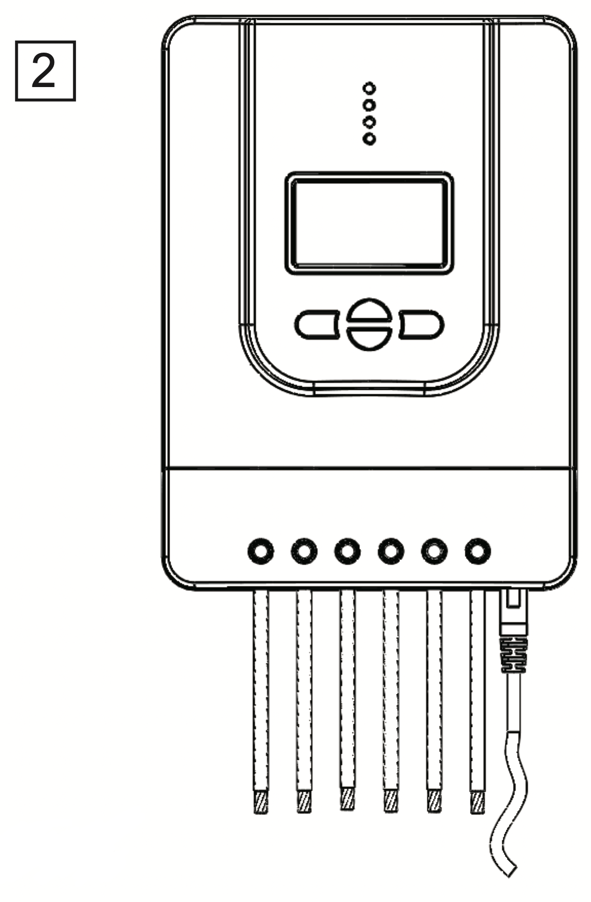
Key Parts
- PV LED Indicator
- Battery LED Indicator
- Load LED Indicator
- System Error LED Indicator
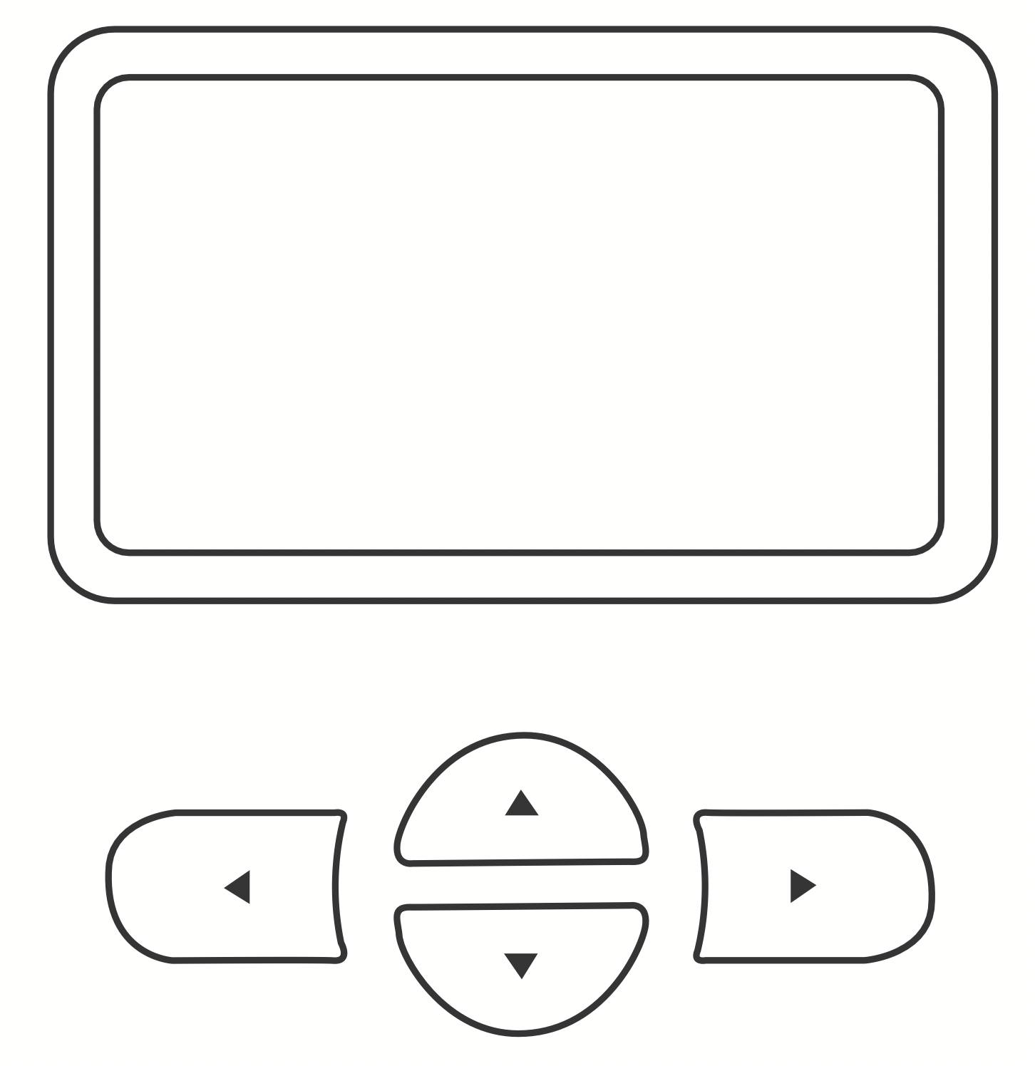
- LCD Screen
- Operating Keys
- Mounting Holes
- Remote Temperature Sensor Port (optional accessory)
- PV Terminals
- Battery Terminals
- Load Terminals
- RS-232 Port (optional accessory)
Installation
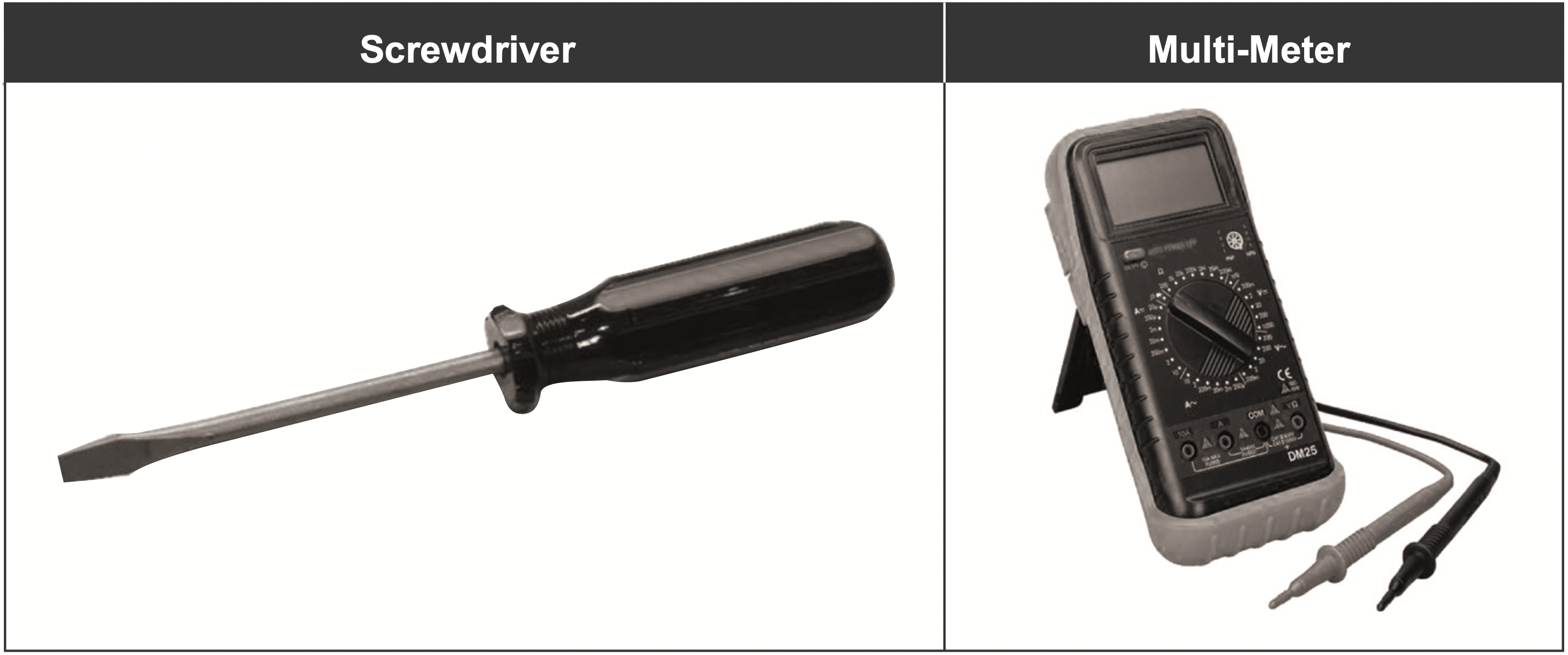
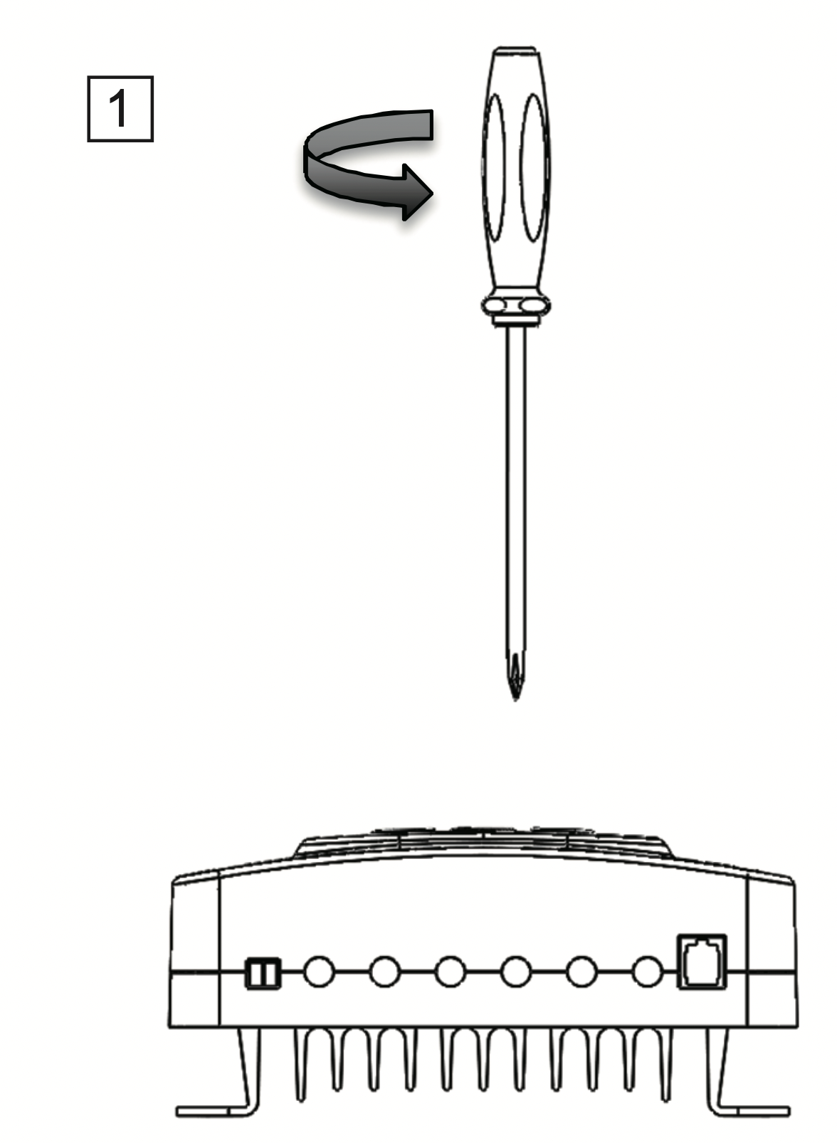
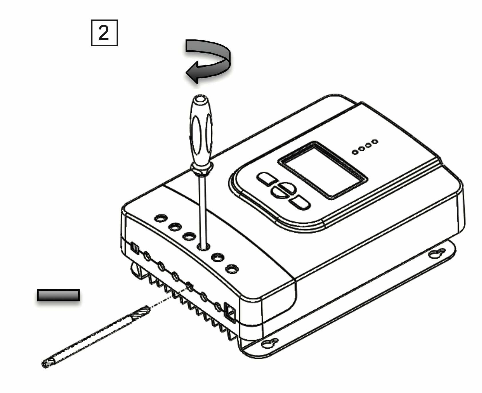
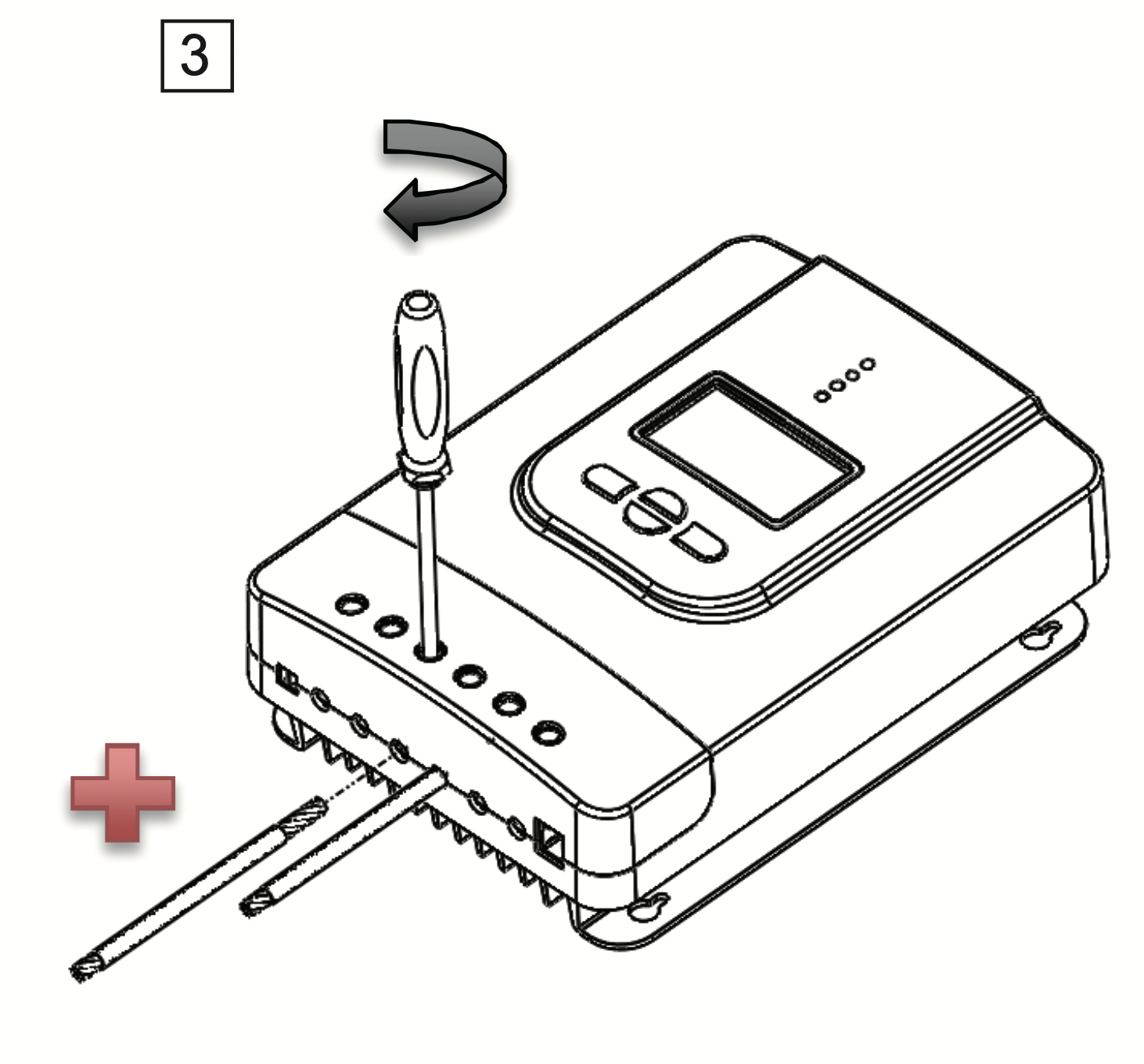
Recommended tools to have before installation:
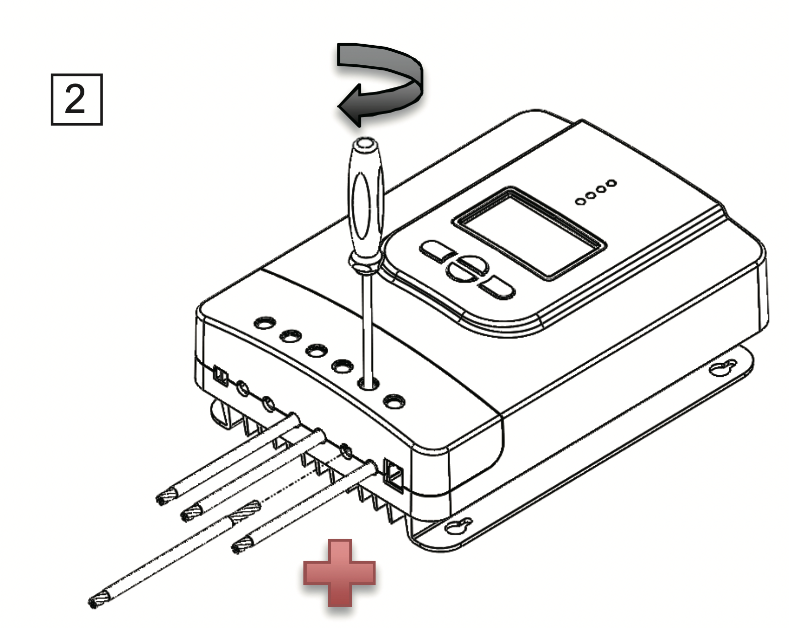
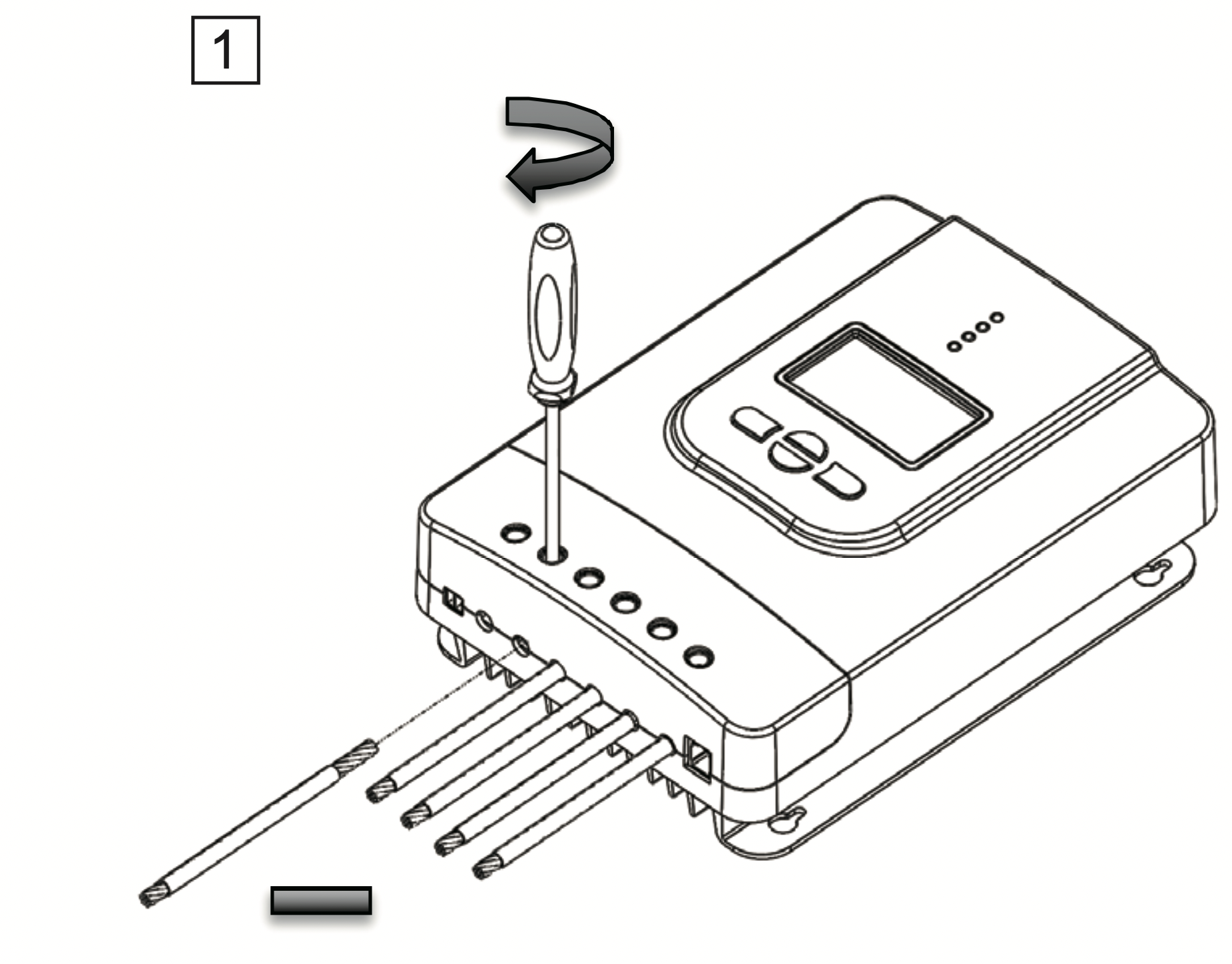
WARNING: Connect battery terminal wires to the charge controller FIRST then connect the solar panel(s) to the charge controller. NEVER connect solar panel to charge controller before the battery.
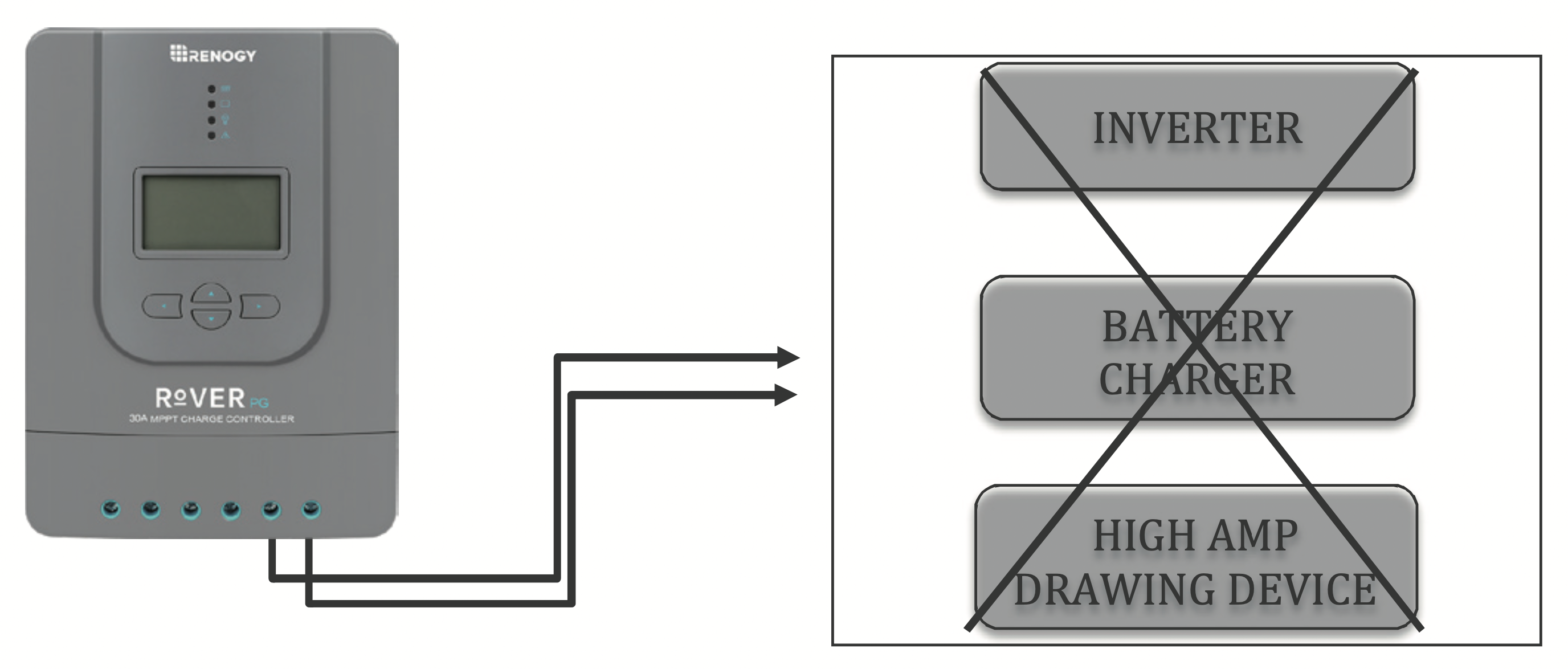
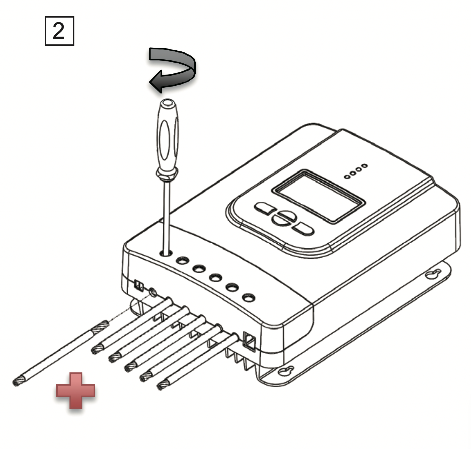
WARNING: Do NOT connect any inverters or battery chargers into the LOAD TERMINAL of the charge controller.
CAUTION: Do not over tighten the screw terminals. This could potentially break the piece that holds the wire to the charge controller.
CAUTION: Refer to the technical specifications for max wire sizes on the controller and for the maximum amperage going through wires.
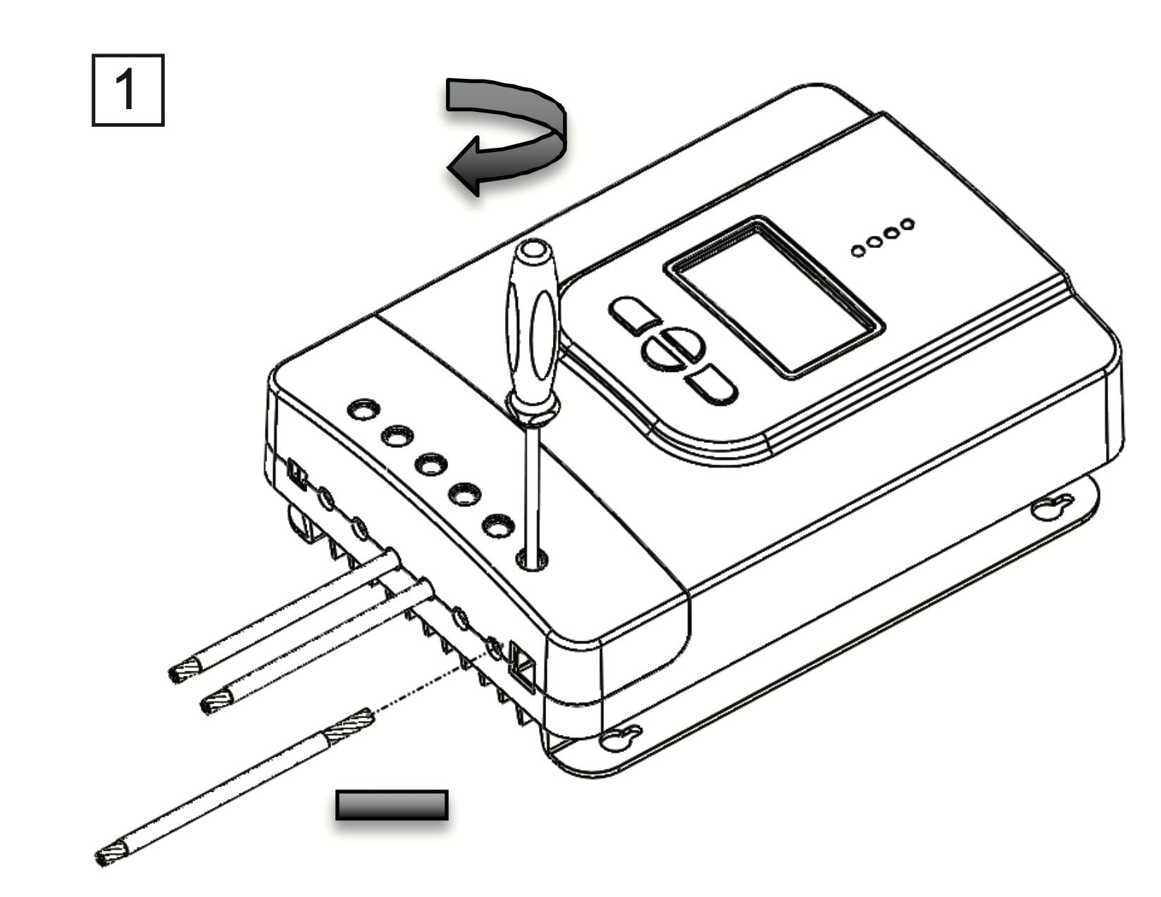
You are now ready to begin connecting your battery to your charge controller.
Battery
Load (optional)
Solar Panels
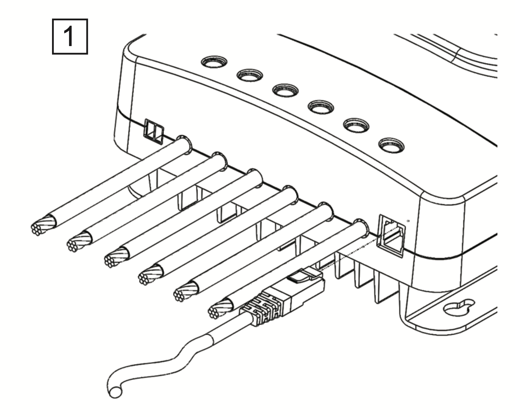
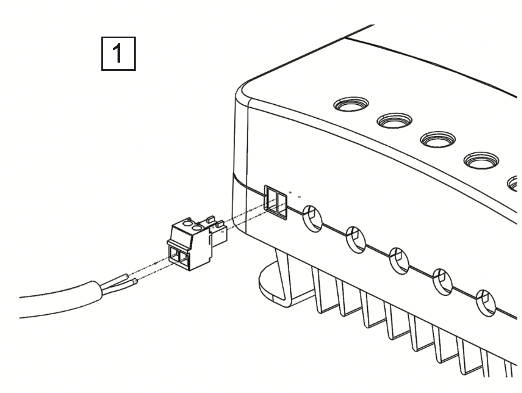
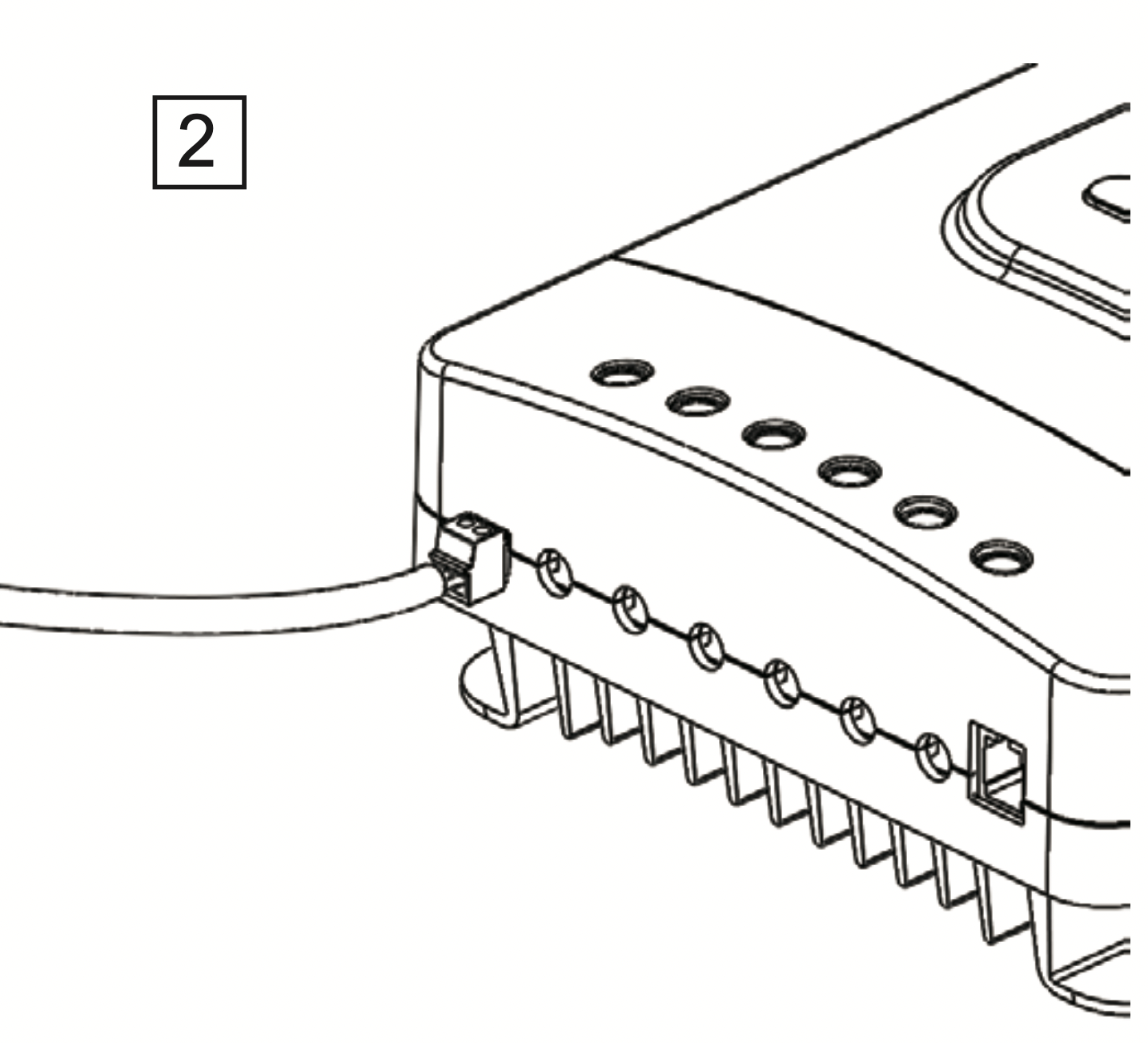
Bluetooth Module communication (optional)
Temperature Sensor (optional, not polarity sensitive)
3. Place the sensor close to the battery
NOTE: Do NOT place the Temperature Sensor lug inside the battery cell.
Mounting Recommendations
WARNING: Never install the controller in a sealed enclosure with flooded batteries. Gas can accumulate and there is a risk of explosion.
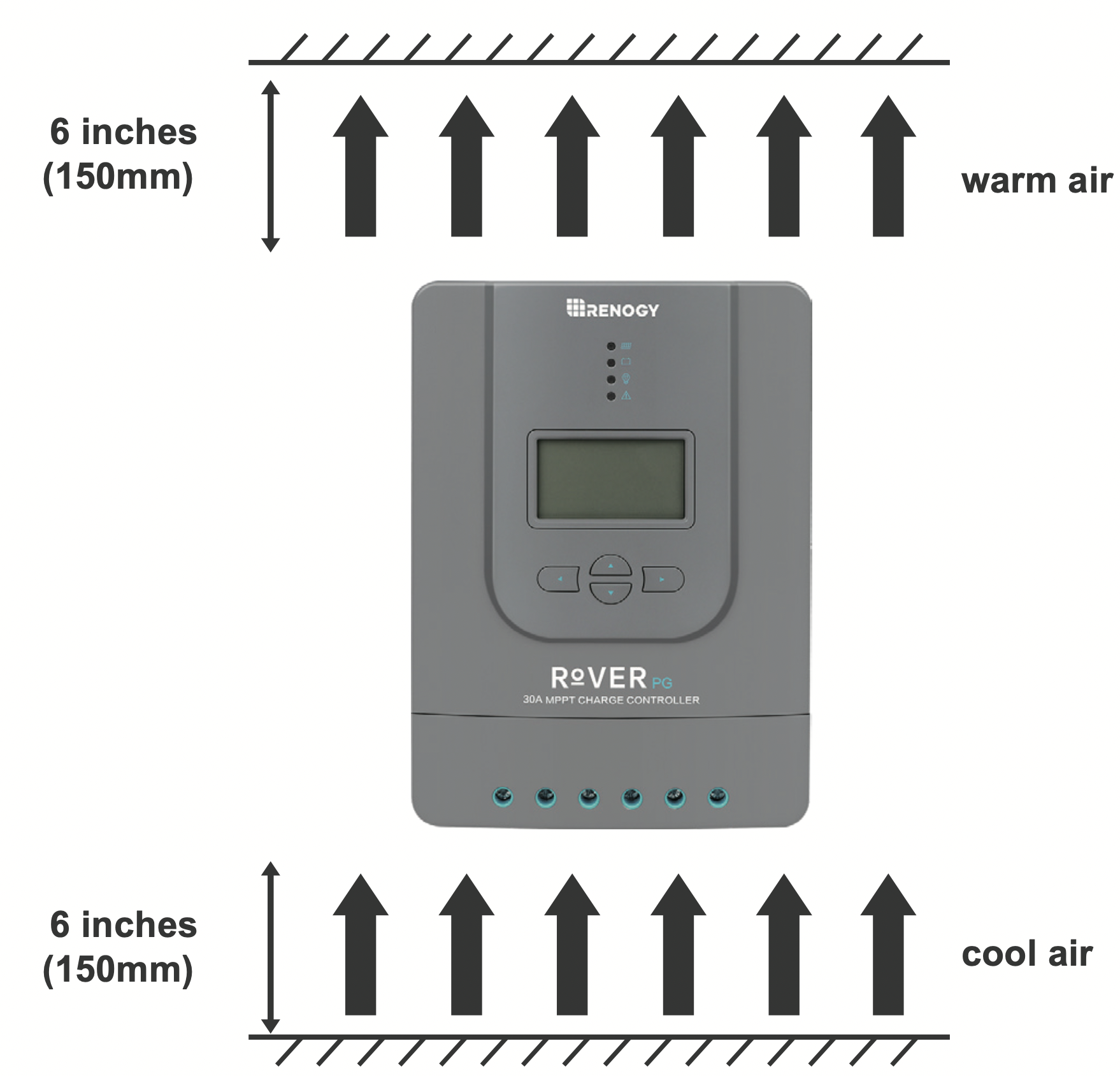
- Choose Mounting Location—place the controller on a vertical surface protected from direct sunlight, high temperatures, and water. Make sure there is good ventilation.
- Check for Clearance—verify that there is sufficient room to run wires, as well as clearance above and below the controller for ventilation. The clearance should be at least 6 inches (150mm).
- Mark Holes
- Drill Holes
- Secure the charge controller.
Mounting Methods
The controller can be mounted using the existing mounting holes or using the included mounting brackets.
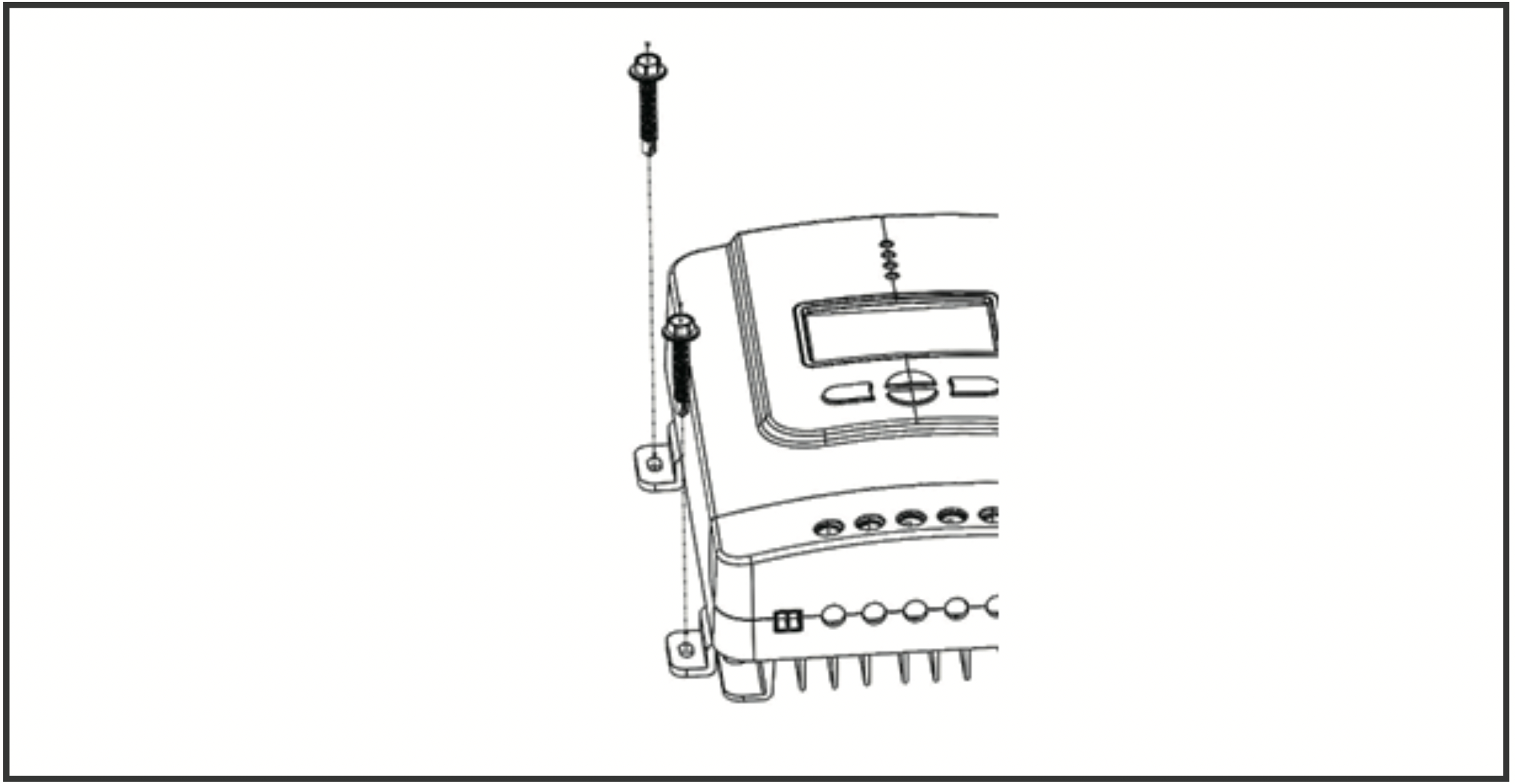
Using Mounting Hole
Step 1. Measure the distance between each mounting hole on the Rover. Using that distance drill 4 screws onto desired surface.
Step 2. Align the Rovers mounting holes with the screws
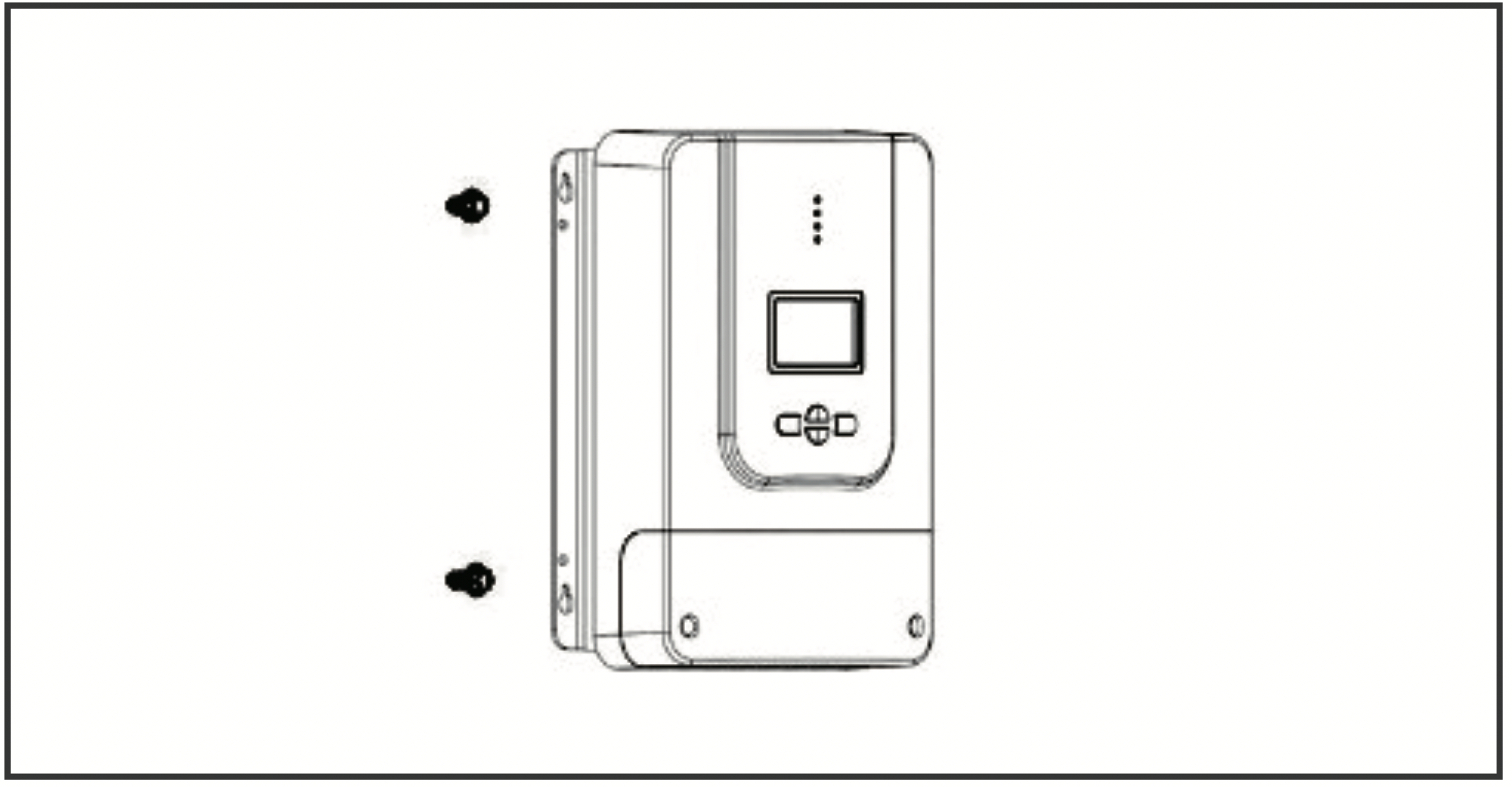
Step 3. Verify all screw heads are inside the mounting holes. Release controller and check if mounting feels secure.
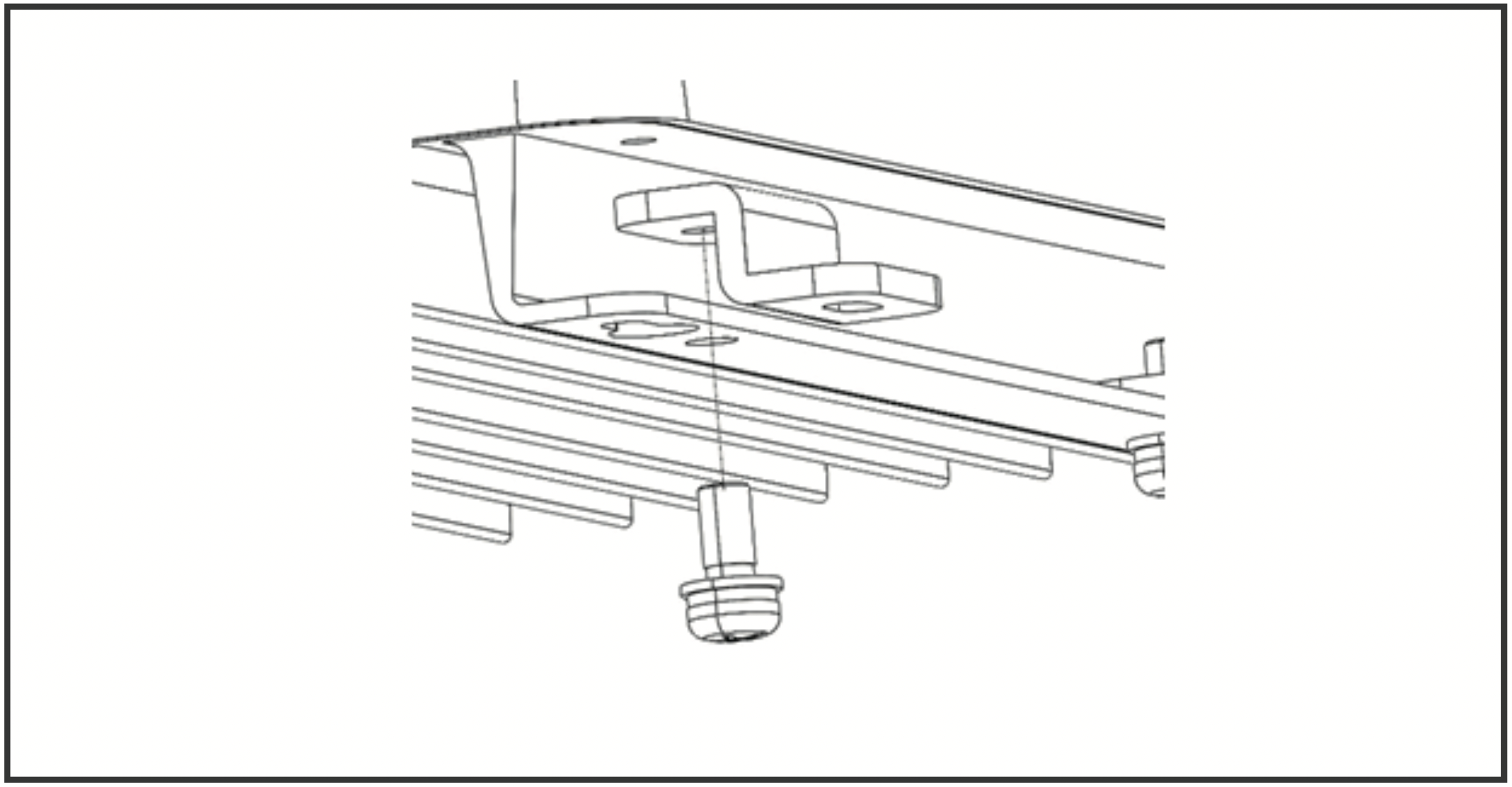
Using Mounting Brackets
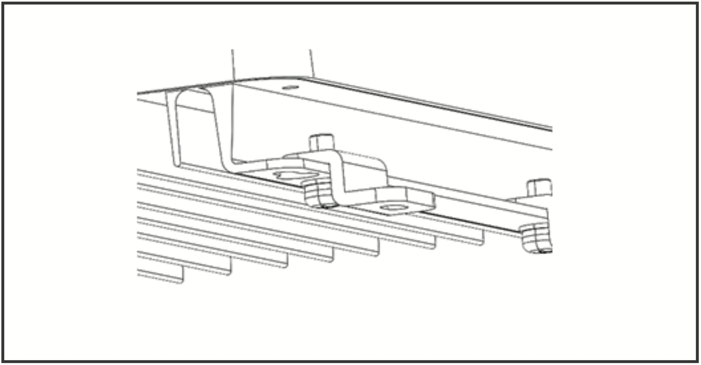
Step 1. Install the brackets using the provided components
Step 2. Align the mounting brackets to desired surface and use the appropriate screws to drill into surface (screws not included)
Step 3. Verify mounting is secure
Operation
Rover PG is very simple to use. Simply connect the batteries, and the controller will automatically determine the battery voltage. The controller comes equipped with an LCD screen and 4 buttons to maneuver though the menus.
Startup Interface
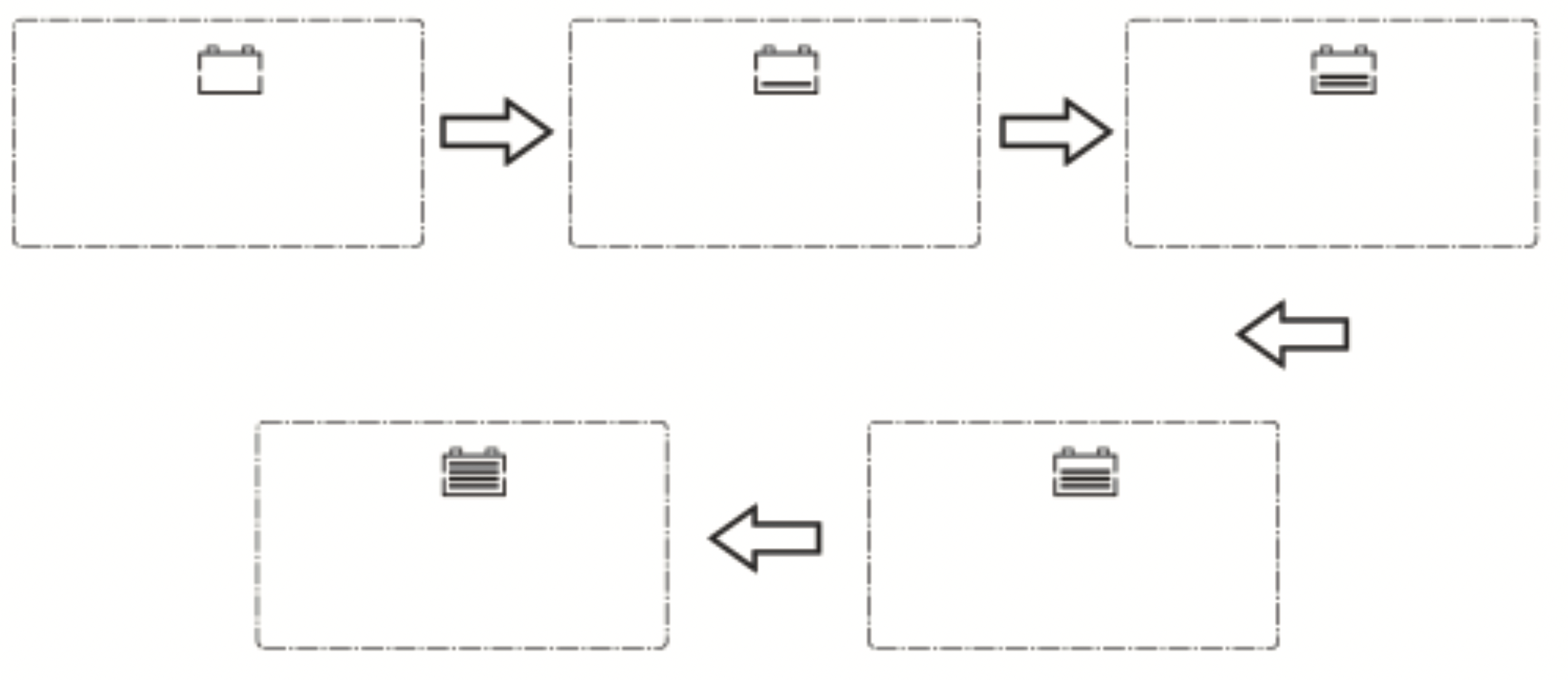
Main Display
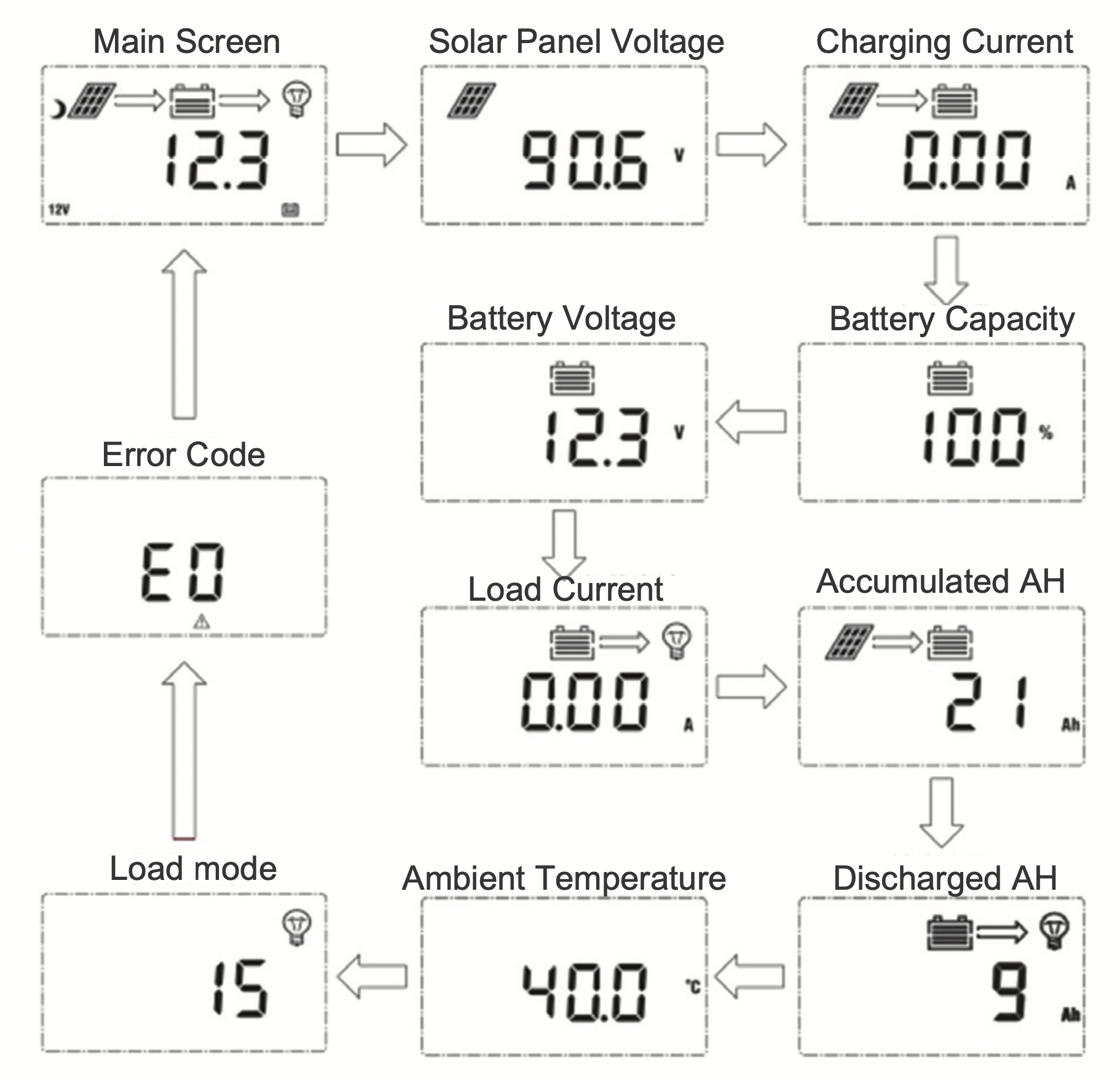
NOTE: The Battery Capacity (SOC%) is estimated based on the charging voltage.
Programming Parameters

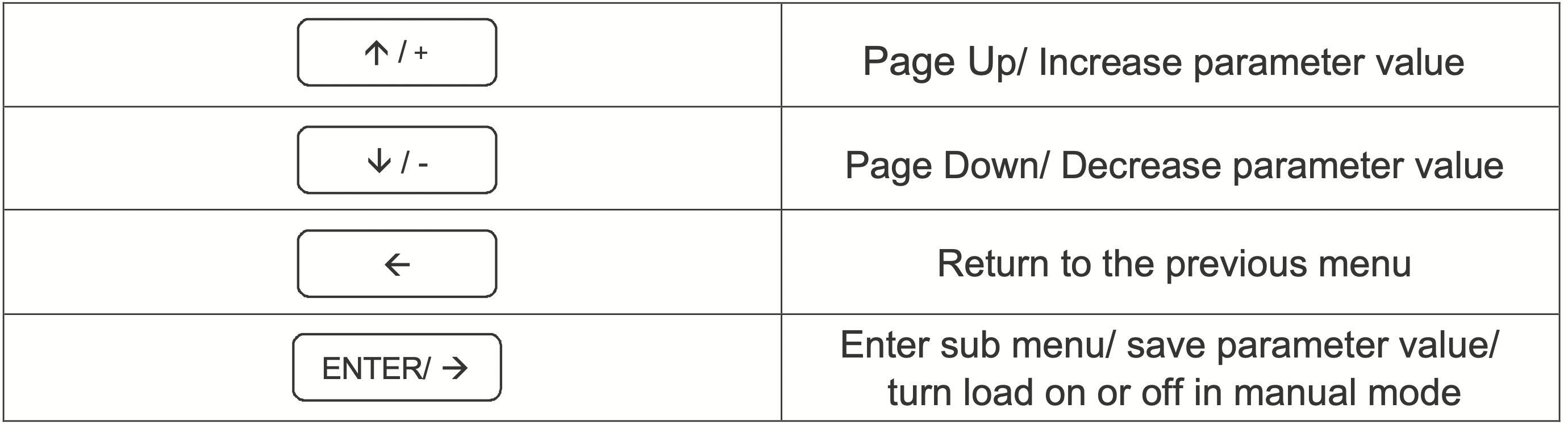
To enter the programming interface simply press and hold the right arrow button. After entering this feature press the Enter/Right button to switch between parameters. To change the parameters, press the Up or Down button. To save the parameter press and hold the Enter/Right button.
The charging parameter setting (Equalizing voltage, Boost voltage, Floating charging voltage, over-discharge return voltage, Over-discharge voltage) are only available under the battery “USER” mode. Press and hold the right arrow to enter the programming settings and continue pressing the right arrow button until you see the desired voltage screen.
NOTE: Battery charging parameters can also be programmed using the Renogy BT APP. Read the corresponding user manuals for more information.
Programming Load Terminal
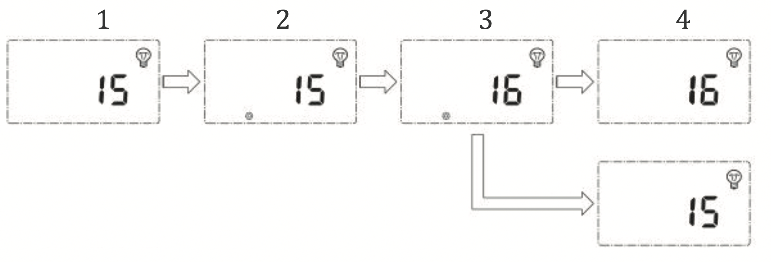
- This screen is displaying the current Load Mode.
- To enter screen 2 press and hold the Enter button. This screen will allow you to change the load mode.
- To change the load mode press the up or down button.
- Once you have selected the desired load mode press the Enter button to save the setting.
- To exit the programming setting press the left button.
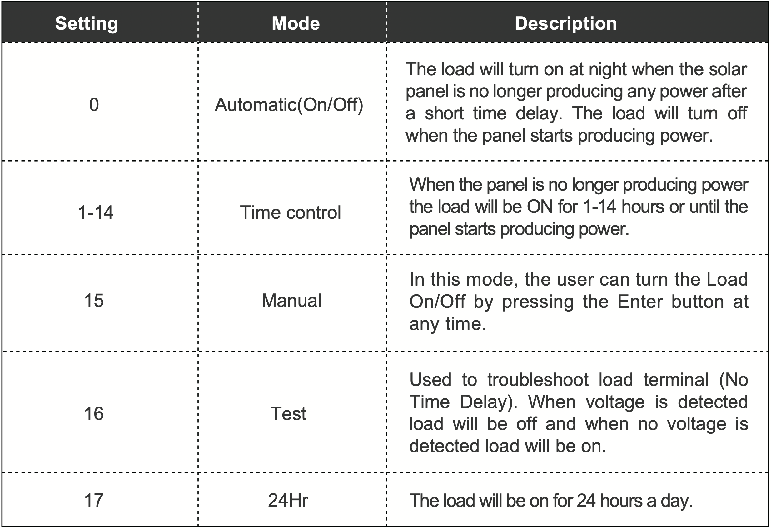
Load Mode Options
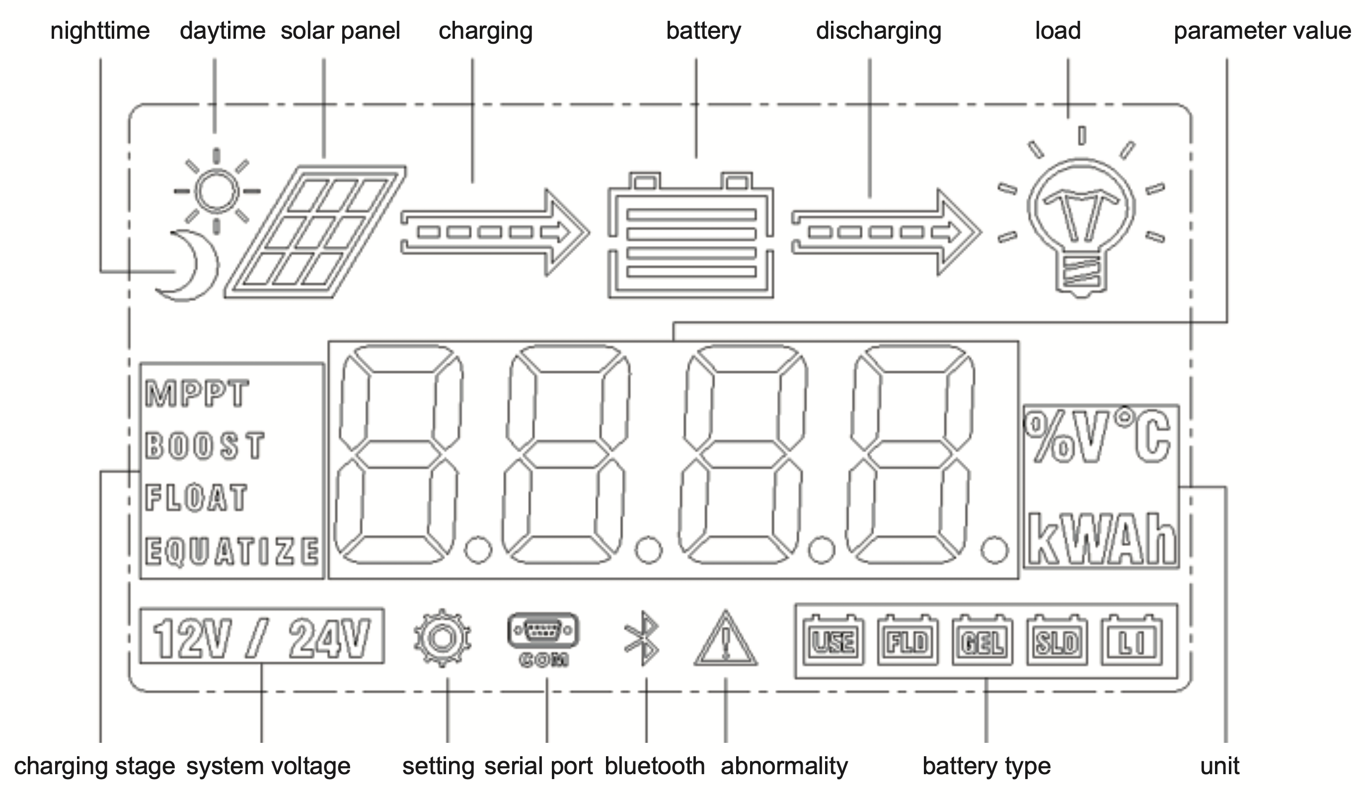
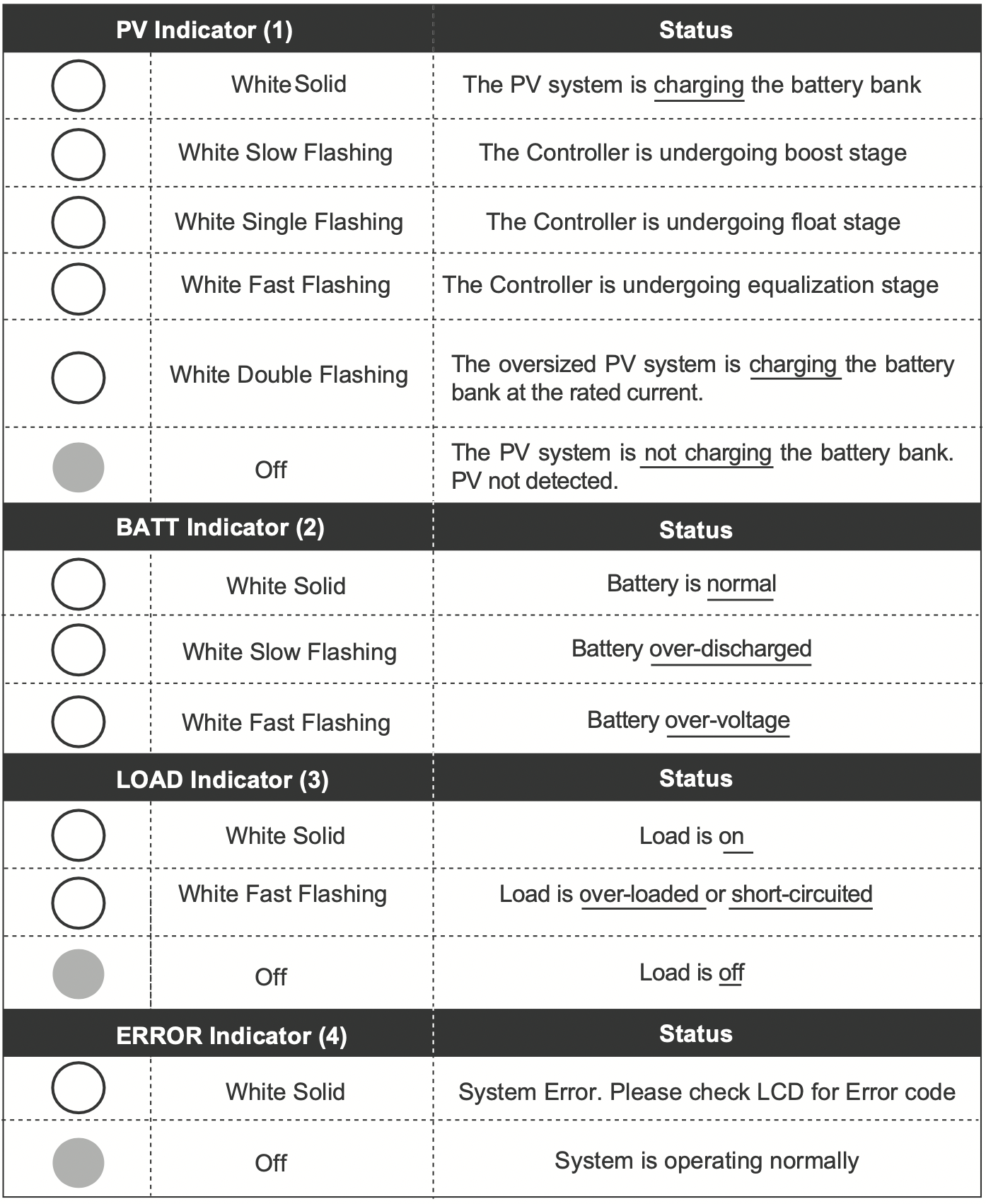
LCD Indicators
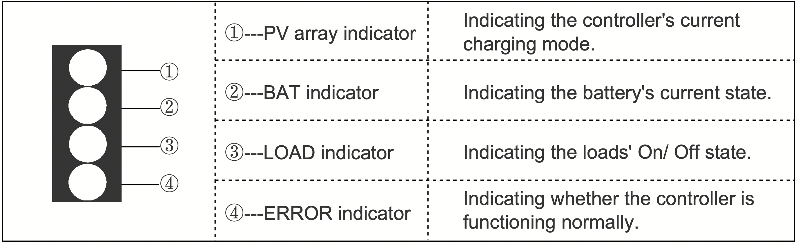
LED Indicators
Rover PG Protections
|
Protection
|
Behavior
|
|
PV Array Short Circuit
|
When PV shot circuit occurs, the controller will stop charging. Clear it to resume normal operation.
|
|
PV Over current
|
The controller will limit the battery charging current to the maximum battery current rating. Therefore, an over-sized solar array will not operate at peak power.
|
|
Load Overload
|
If the current exceeds the maximum load current rating 1.05 times, the controller will disconnect the load. Overloading must be cleared up by reducing the load and restarting the controller.
|
|
Load Short Circuit
|
Fully protected against the load wiring short-circuit. Once the load short (more than quadruple rate current), the load short protection will start automatically. After 5 automatic load reconnect attempts, the faults must be cleared by restarting the controller.
|
|
PV Reverse Polarity
|
The controller will not operate if the PV wires are switched. Wire them correctly to resume normal controller operation.
|
|
Battery Reverse Polarity
|
The controller will not operate if the battery wires are switched. Wire them correctly to resume normal controller operation.
|
|
Over -Temperature
|
If the temperature of the controller heat sink exceeds 65℃, the controller will automatically start reducing the charging current. The controller will shut down when the temperature exceeds 85℃.
|
System Status Troubleshooting
|
PVindicator
|
Troubleshoot
|
|
Off during day light
|
Ensure that the PV wires are correctly and tightly secured inside the charge controller PV terminals. Use a multi-meter to make sure the poles are correctly connected to the charge controller.
|
|
BATT Indicator
|
Troubleshoot
|
|
White Slow Flashing
|
Disconnect loads, if any, and let the PV modules charge the battery bank. Use a multi-meter to frequently check on any change in battery voltage to see if condition improves. This should ensure a fast charge. Otherwise, monitor the system and check to see if system improves.
|
|
White Fast Flashing
|
Using a multimeter check the battery voltage and verify it is not exceeding 32 volts.
|
|
Load Indicator
|
Troubleshoot
|
|
White Fast Flashing
|
The Load circuit on the controller is being shorted or overloaded. Please ensure the device is properly connected to the controller and make sure it does not exceed 20A (DC).
|
|
Error Indicator
|
Troubleshoot
|
|
White Solid
|
System Error. Please check LCD for Error code
|
Error Codes
|
Error Number
|
Description
|
|
E0
|
No error detected
|
|
E1
|
Battery over-discharged
|
|
E2
|
Battery over-voltage
|
|
E3
|
Battery under-voltage
|
|
E4
|
Load short circuit
|
|
E5
|
Load overloaded
|
|
E6
|
Controller over-temperature
|
|
E8
|
PV input over-current
|
|
E10
|
PV over-voltage
|
Maintenance
WARNING: Risk of Electric Shock! Make sure that all power is turned off before touching the terminals on the charge controller.
For best controller performance, it is recommended that these tasks be performed from time to time.
- Check that controller is mounted in a clean, dry, and ventilated area.
- Check wiring going into the charge controller and make sure there is no wire damage or wear.
- Tighten all terminals and inspect any loose, broken, or burnt up connections.
- Make sure LED readings are consistent. Take necessary corrective action.
- Check to make sure none of the terminals have any corrosion, insulation damage, high temperature, or any burnt/discoloration marks.