Conned battery terminal wires to the charge controller FIRST, then conned the solar panel(s) to the charge controller. NEVER conned solar panel to charge controller before the battery.
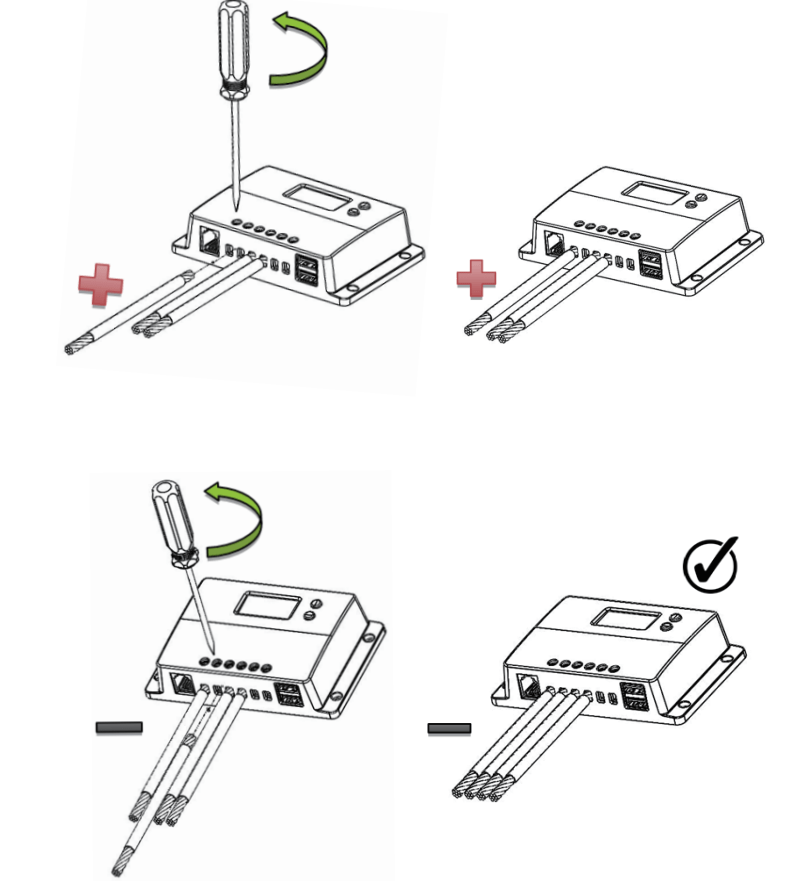
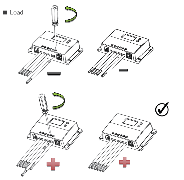
Do not over-torque or over tighten the screw terminals. This could potentially break the piece that holds the wire to the charge controller.
Refer to the technical specifications for max wire sizes on the controller and for the maximum amperage going through wires.
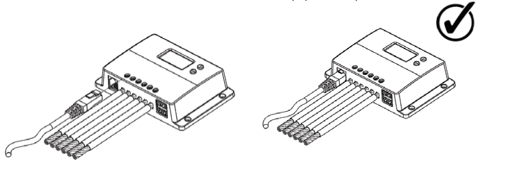
Wiring
Battery
Solar Panel
Load
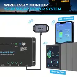
Bluetooth Module Communication (optional)
Mounting Recommendations
Never install the controller in a sealed enclosure with flooded batteries. Gas can accumulate and there is a risk of explosion.
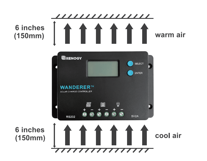
Choose Mounting Location—place the controller on a vertical surface protected from direct sunlight, high temperatures, and water. Make sure there is good ventilation.
Check for Clearance—verify that there is sufficient room to run wires, as well as clearance above and below the controller for ventilation. The clearance should be at least 6 inches (150mm).
Mark Holes
Drill Holes
Secure the charge controller.
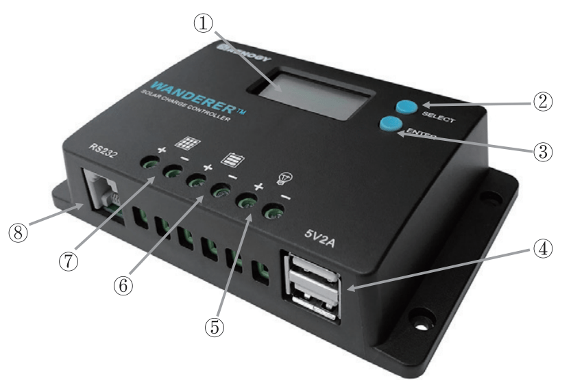
Operation
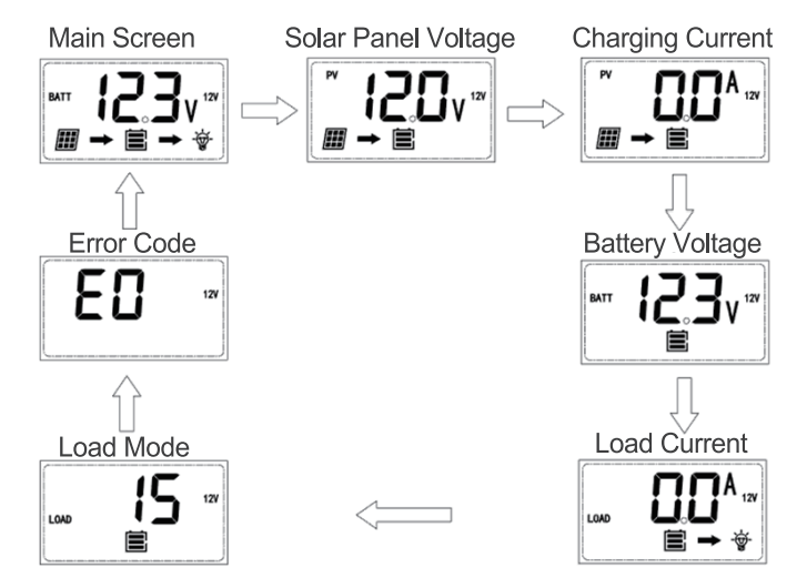
After connecting the battery to the charge controller, the controller will turn on automatically. Assuming normal operation, the charge controller will cycle through different displays. The user can adjust some parameters based on the display screen. The user can manually cycle through the display screens by using the “SELECT and “ENTER” buttons.
SELECT Cycles forwards through the different display screens.
ENTER Cycles backwards through the different select screens &Tum the load ON/OFF in the Manual Mode
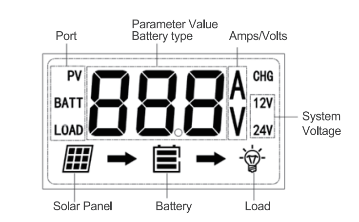
Main Display
LCD Indicators
Icon or Value
State
Description
Steady on
Solar Panels Charging Battery
3 Bars Flashing
Battery Voltage (16.1V+)
3 Bars
Battery Voltage (12.9V- 16.0V)
2 Bars
Battery Voltage (12.5-12.8V)
1 Bar
Battery Voltage (11.6-12.4V)
No Bars
Battery Voltage (11.5V and below)
No Bars Flashing
Battery Voltage (10.9V and below)
Steady on
Load is On
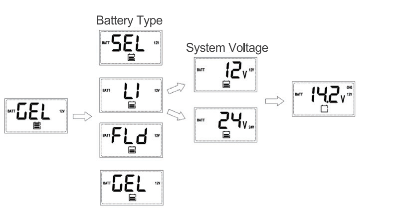
Programming Battery Type
To enter the battery programming settings hover over the Battery Voltage screen and press down the Enter button. When the battery type starts to flash press the Select button to cycle through the battery types and press Enter to finalize selection. When selecting the Lithium setting the user can change battery voltage from 12V to 24V and select the charging voltage.
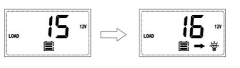
Programming Load Terminal
To enter the load programming settings hover over the Load Mode screen and hold the Enter button. When the number starts to flash press the Select button to cycle through the load types and press Enter to finalize selection.
Setting
Mode
Description
0
Automatic
(On/Off)
The load will turn on at night when the solar panel is no longer producing any power after a short time delay. The load will turn off when the panel starts producing power.
1-14
Time
control
When the panel is no longer producing power, the load will be ON for 1-14 hours or until the panel starts producing power.
15
Manual
In this mode, the user can turn the Load On/Off by pressing the Enter button at any time.
16
Test
Used to troubleshoot load terminal (No Time Delay). When voltage is detected load will be off and when no voltage is detected load will be on.
17
24Hr
The load will be on for 24 hours a day.
Wanderer Protections
Protection
Behavior
PV Array Short Circuit
When PV short circuit occurs, the controller will stop charging. Clear it to resume normal operation
PV Over current
The controller will limit the battery charging current to the maximum battery current rating. Therefore, an over-sized solar array will not operate at peak power.
Load Overload
If the current exceeds the maximum load current rating 1.05 times, the controller will disconnect the load. Overloading must be cleared up by reducing the load and restarting the controller.
Load Short Circuit
Fully protected against the load wiring short-circuit. Once the load short (more than quadruple rate current), the load short protection will start automatically. After 5 automatic load reconnect attempts, the faults must be cleared by restarting the controller.
PV Reverse Polarity
The controller will not operate if the PV wires are switched. Wire them correctly to resume normal controller operation.
Battery Reverse Polarity
The controller will not operate if the battery wires are switched. Wire them correctly to resume normal controller operation.
Error Codes
Error Number
Description
E0
No error detected
E01
Battery over-discharged
E02
Battery over-voltage
E04
Load short circuit
E05
Load overloaded
E06
Controller over-temperature
E08
PV input over-current
E10
PV over-voltage
E13
PV reverse polarity
E14
Battery reverse polarity
Maintenance
Risk of Electric Shock! Make sure that all power is turned off before touching the terminals on the charge controller.
For best controller performance, it is recommended that these tasks be performed from time to time.
Check that controller is mounted in a clean, dry, and ventilated area.
Check wiring going into the charge controller and make sure there is no wire damage or wear.
Tighten all terminals and inspect any loose, broken, or burnt up connections.
Check to make sure none of the terminals have any corrosion, insulation damage, high temperature, or any burnt/discoloration marks.
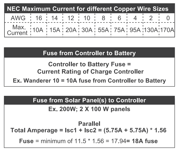
Fusing
Fusing is a recommendation in PV systems to provide a safety measure for connections going from panel to controller and controller to battery. Remember to always use the recommended wire gauge size based on the PV system and the controller.
 Do not over-torque or over tighten the screw terminals. This could potentially break the piece that holds the wire to the charge controller.
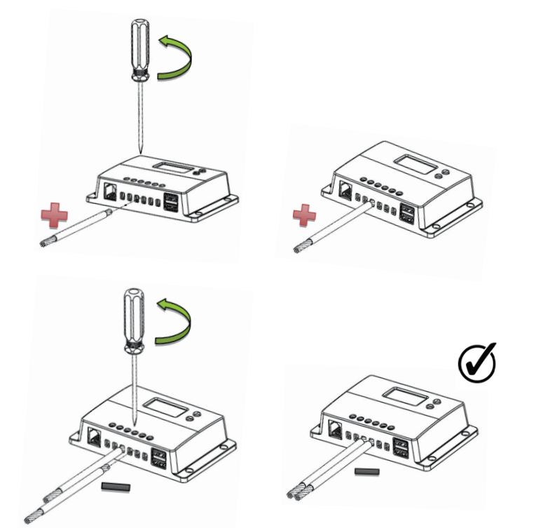


 Risk of Electric Shock! Make sure that all power is turned off before touching the terminals on the charge controller.