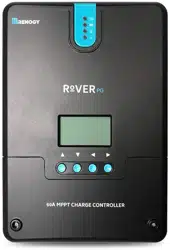
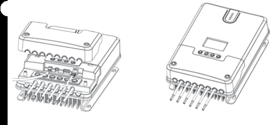
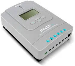
The Rover PG Series charge controllers are Intelligent positive ground controllers suitable for various off-grid solar applications. It protects the battery from being over-charged by the solar modules and over-discharged by the loads. The controller features a smart tracking algorithm that maximizes the energy from the solar PV module(s) and charge the battery. At the same time, the low voltage disconnect function (LVD) will prevent the battery from over-discharging.
The Rover PG’s charging process has been optimized for long battery life and improved system performance. The comprehensive self-diagnostics and electronic protection functions can prevent damage from installation mistakes or system faults.
Key Features
Automatically detect 12V/24V/36V/48V DC system voltages
Innovative MPPT technology with high tracking efficiency up to 99% and peak conversion efficiency of 98%
Deep cycle Sealed, Gel, Flooded and Lithium battery option ready
Electronic protection: Overcharging, over-discharging, overload, and short circuit
Reverse protection: Any combination of solar module and battery, without causing damage to any component
Customizable charging voltages
RS232 port to communicate with BT-1 Bluetooth Module or DM-1 4G Data ModuleCharges over discharged lithium batteries
Positive ground charge controller
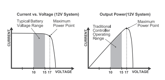
MPPT Technology
The MPPT Charge Controller utilizes Maximum Power Point Tracking technology to extract maximum power from the solar module(s). The tracking algorithm is fully automatic and does not require user adjustment. MPPT technology will track the array’s maximum power point voltage (Vmp) as it varies with weather conditions, ensuring that the maximum power is harvested from the array throughout the course of the day.
Current Boost
In many cases, the MPPT charge controller will “boost” up the current in the solar system. The current does not come out of thin air. Instead, the power generated in the solar panels is the same power that is transmitted into the battery bank. Power is the product of Voltage (V) x Amperage (A).
Therefore, assuming 100% efficiency:
Power In = Power Out
Volts In * Amps In = Volts out * Amps out
Although MPPT controllers are not 100% efficient, they are very close at about 92-95% efficient. Therefore, when the user has a solar system whose Vmp is greater than the battery bank voltage, then that potential difference is proportional to the current boost. The voltage generated at the solar module needs to be stepped down to a rate that could charge the battery in a stable fashion by which the amperage is boosted accordingly to the drop. It is entirely possible to have a solar module generate 8 amps going into the charge controller and likewise have the charge controller send 10 amps to the battery bank. This is the essence of the MPPT charge controllers and their advantage over traditional charge controllers. In traditional charge controllers, that stepped down voltage amount is wasted because the controller algorithm can only dissipate it as heat. The following demonstrates a graphical point regarding the output of MPPT technology.
Limiting Effectiveness
Temperature is a huge enemy of solar modules. As the environmental temperature increases, the operating voltage (Vmp) is reduced and limits the power generation of the solar module. Despite the effectiveness of MPPT technology, the charging algorithm will possibly not have much to work with and therefore there is an inevitable decrease in performance. In this scenario, it would be preferred to have modules with higher nominal voltage, so that despite the drop in performance of the panel, the battery is still receiving a current boost because of the proportional drop in module voltage.
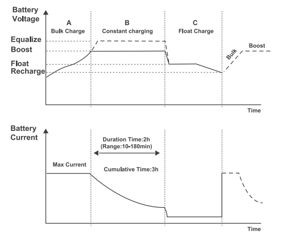
Four Charging Stages
The Rover PG MPPT charge controller has a 4-stage battery charging algorithm for a rapid, efficient, and safe battery charging. They include: Bulk Charge, Boost Charge, Float Charge, and Equalization
Bulk Charge:This algorithm is used for day to day charging. It uses 100% of available solar power to recharge the battery and is equivalent to constant current. In this stage the battery voltage has not yet reached constant voltage (Equalize or Boost), the controller operates in constant current mode, delivering its maximum current to the batteries (MPPT Charging).
Constant Charging;When the battery reaches the constant voltage set point, the controller will start to operate in constant charging mode, where it is no longer MPPT charging. The current will drop gradually. This has two stages, equalize and boost and they are not carried out constantly in a full charge process to avoid too much gas precipitation or overheating of the battery.
Boost Charge:Boost stage maintains a charge for 2 hours by default. The user can adjust the constant time and preset value of boost per their demand.
Float Charge:After the constant voltage stage, the controller will reduce the battery voltage to a float voltage set point. Once the battery is fully charged, there will be no more chemical reactions and all the charge current would turn into heat or gas. Because of this,
The charge controller will reduce the voltage charge to smaller quantity, while lightly charging the battery. The purpose for this is to offset the power consumption while maintaining a full battery storage capacity. In the event that a load drawn from the battery exceeds the charge current, the controller will no longer be able to maintain the battery to a Float set point and the controller will end the float charge stage and refer back to bulk charging.
Equalization; Is carried out every 28 days of the month. It is intentional overcharging of the battery for a controlled period of time. Certain types of batteries benefit from periodic equalizing charge, which can stir the electrolyte, balance battery voltage and complete chemical reaction. Equalizing charge increases the battery voltage, higher than the standard complement voltage, which gasifies the battery electrolyte.
Lithium Battery Activation
The Rover PG MPPT charge controller has a reactivation feature to awaken a sleeping lithium battery. The protection circuit of lithium battery will typically turn the battery off and make it unusable if over-discharged. This can happen when storing a lithium battery pack in a discharged state for any length of time as self-discharge would gradually deplete the remaining charge. Without the wake-up feature to reactivate and recharge batteries, these batteries would become unserviceable and the packs would be discarded. The Rover PG will apply a small charge current to activate the protection circuit and if a correct cell voltage can be reached, it starts a normal charge.
Common Positive Grounding
The Rover PG series are positive ground controllers. This means all positive terminals are bonded together. Any positive connection of solar, load or battery can be earth grounded as required. The solar panels, loads and battery will be connected to the Rover PG the same way as a negative ground controller. The difference is when grounding the Rover PG there can only be a single ground point, either ground the positive line of the solar panels, the positive line of the load terminal or the positive line of the battery bank. Do not ground the Rover PG when adding it to a negative ground system.
Additional Components
Additional components included in the package:
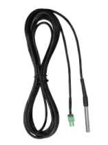
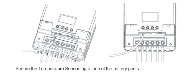
Remote Temperature Sensor;
This sensor measures the temperature at the battery and uses this data for very accurate temperature compensation. Accurate temperature compensation is important in ensuring proper battery charging regardless of the temperature.
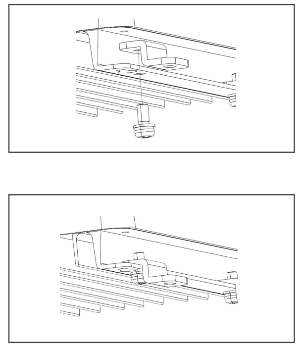
Mounting Brackets;
These brackets can be used to mount the Rover PG MPPT charge controller on any flat surface. The screws to mount the brackets to the charge controller are included, screws to mount charge controller to surface are not included.
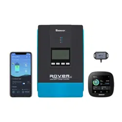
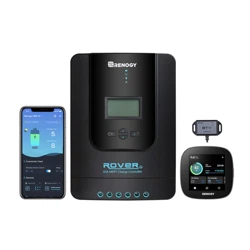
Optional Components
Optional components that require a separate purchase:
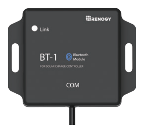
Renogy BT-1 Bluetooth Module:
The BT-1 Bluetooth module is a great addition to any Renogy charge controllers with a RS232 port and is used to pair charge controllers with the Renogy BT App. After pairing is done you can monitor your system and change parameters directly from you cell phone or tablet. No more wondering how your system is performing, now you can see performance in real time without the need of checking on the controller’s LCD.
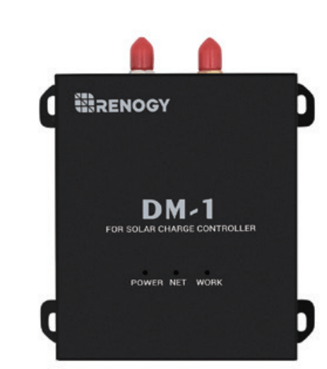
Renogy DM-1 4G Data Module:
The DM-1 4G Module is capable of connecting to select Renogy charge controllers through an RS232, and is used to pair charge controllers with Renogy 4G monitoring app. This app allows you to conveniently monitor your system and charge system parameters remotely from anywhere 4G LTE network service is available
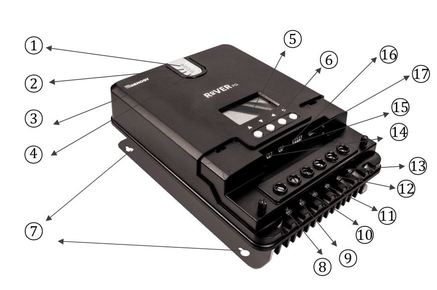
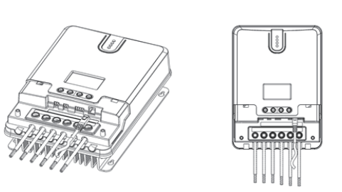
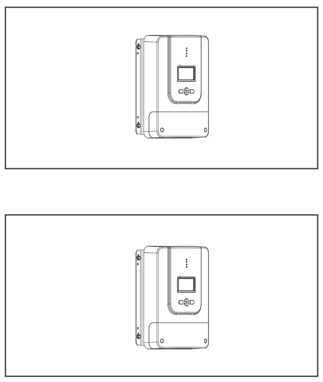
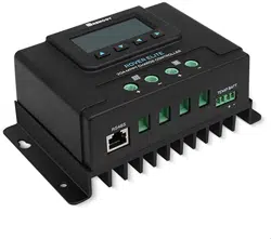
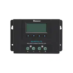
Identification of Parts
Key Parts
Charging Indicator
Battery Indicator
Load Indicator
Abnormality Indicator
LCD Screen.
Operating Keys
Installation Hole
Solar panel “+" Interface
Solar panel Interface
Battery Interface
Load Interface
Battery “+” Interface
Load “+” Interface
External Temperature Sampling Interface
Battery Voltage Compensation Interface
RS485 Communication Interface
RS232 Communication Interface
Installation
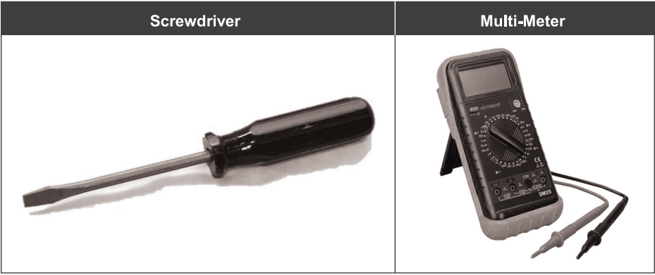
Recommended tools to have before installation:
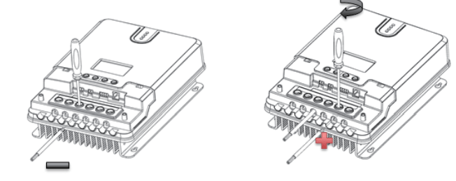
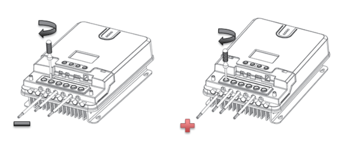
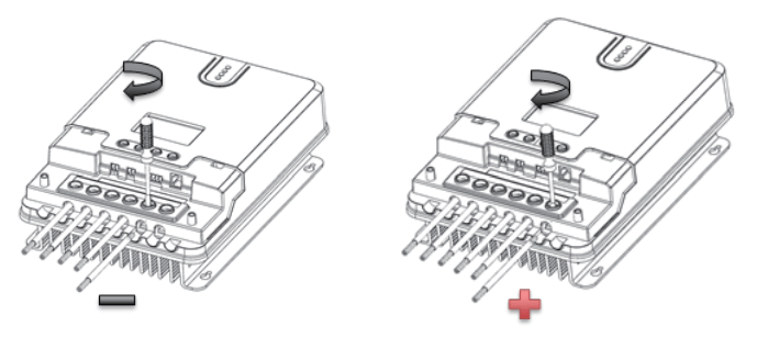
Warning: Connect battery terminal wires to the charge controller FIRST then connect the solar panel(s) to the charge controller. NEVER connect solar panel to charge controller before the battery.
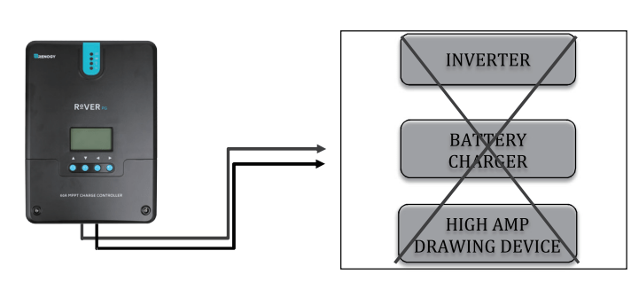
Warning: Do NOT connect any inverters or battery changers into the LOAD TERMINAL of the charge controller.
Caution: Do not over tighten the screw terminals. This could potentially break the piece that holds the wire to the charge controller.
Caution: Refer to the technical specifications for max wire sizes on the controller and for the maximum amperage going through wires.
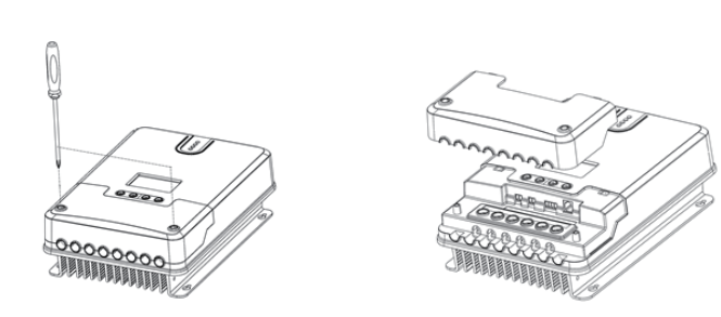
Remove Cover
Battery
Solar Panels
Load (optional)
Bluetooth Module communication (optional)
Temperature Sensor (optional, not polarity sensitive)
Install Cover
Mounting Recommendations
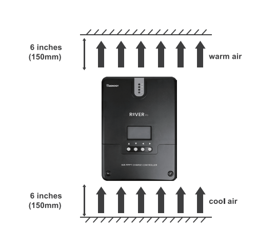
Choose Mounting Location—place the controller on a vertical surface protected from direct sunlight, high temperatures, and water. Make sure there is good ventilation.
Check for Clearance—verify that there is sufficient room to run wires, as well as clearance above and below the controller for ventilation. The clearance should be at least 6 inches (150mm).
Mark Holes
Drill Holes
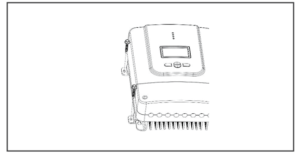
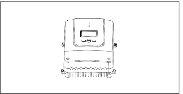
Secure the charge controller.
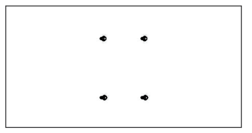
Using Mounting Holes
Step 1. Measure the distance between each mounting hole on the Rover PG. Using that distance drill 4 screws onto desired surface.
Step 2. Align the Rovers mounting holes with the screws
Step 3. Verify all screw heads are Inside the mounting holes. Release controller and check if mounting feels secure
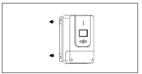
Using Mounting Brackets
Step 1. Install the brackets using the provided components
Step 2. Align the mounting brackets to desired surface and use the appropriate screws to drill surface(screws not included)
Step 3. Verify mounting is secure
Operation
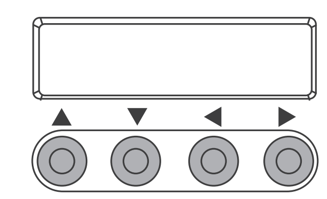
Rover is very simple to use. Simply connect the batteries, and the controller will automatically determine the battery voltage. The controller comes equipped with an LCD screen and 4 buttons to maneuver though the menus.
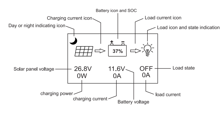
Main Display
Page Up/ Increase parameter value
Page Down/ Decrease parameter value
Return to the previous menu
Enter sub menu/ save parameter value/ turn load on or off in manual mode
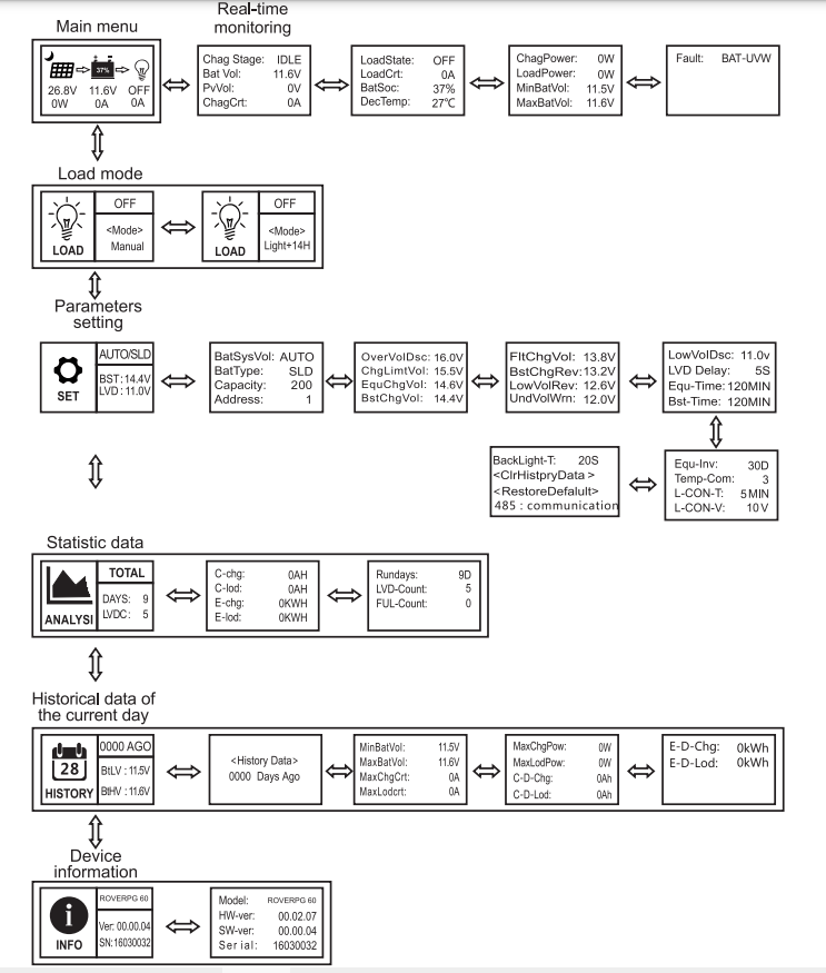
Main Menu
Icon or Value
State
Description
Steady on
Nighttime
Steady on
Daytime
Steady on
A dynamic arrow indicates charging is in progress.
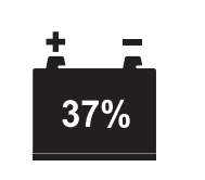
0-100%
Current battery capacity
0% Slow Flashing
Battery over-discharged
100% Flash Flashing
Battery over-voltage
Steady on
Load Terminal in on
Steady on
Load Terminal is off
Fast Flashing
Overload or short-circuit protection
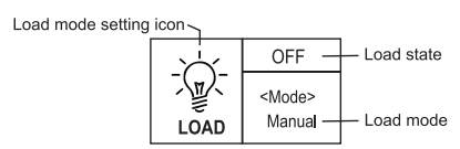
Real-Time Monitoring
To view this screen in the main menu, tap the Right arrow button. To change between screens, press the up or down buttons. To return to the main menu screen press the left arrow button.
If the characters displayed on top of "<Mode>" are "ON", it indicates that the load is switched on
Tap " Right Arrow Button" to enter the load setting mode, and right below the "<Mode>", the mode characters or digits will begin to flash. Use" Up and Down Arrow Buttons" to select any one from the load modes listed in the following table and tap " Right Arrow Button" again to complete the load mode setting.
Press and hold" Right Arrow Button" in any menu but not the setting mode: if the current load mode is "manual mode", pressing and holding the key will switch on/ off the load; if the current load mode is not "manual mode , pressing and holding the key will cause the display to skip to the load mode setting interface and a reminder wifi pop up telling the user in this mode, pressing and holding the key will not switch on/ off the load.
Load Mode Options
Load Mode
Mode
Description
Light-*- On
Solar Light Control Mode
The load will turn on at night when the solar panel is no longer producing any power after a short time delay. The load will turn off when the panel starts producing power.
Light-*- 01H-14H
Time control
When the panel is no longer producing power the load will be ON for 1-14 hours or until the panel starts producing power.
Manual
Manual Mode
In this mode, the user can turn the Load On/Off by pressing the Enter button at any time.
Debug
Test
Used to troubleshoot load terminal (No Time Delay). When voltage is detected load will be off and when no voltage is detected load will be on.
Normal On
24Hr
The load will be on for 24 hours a day.
Parameter Settings
To enter the following settings, in the parameters setting screen press the Right arrow button.
Screen
Parameter
Displayed Parameter
Description
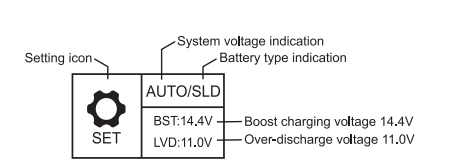
1
Battery system voltage
BatSysVol:
12v,24v,36v,48v, AUTO
Battery type
BatType:
“SLD” Sealed lead-add battery “FLD’ Flooded lead-add battery “GEL” Gel battery “Li” Lithium battery “USE’ user defined
Nominal battery capacity
Capacity:
0-9999
Device address
Address:
1-60
2
Overvoltage threshold
OverVolDsc:
9.0-17.0V
Charging limit voltage
ChgLimitVol:
9.0-17.0V
Equalization Voltage
EquChgVol:
9.0-17.0V
Boost charging voltage
BstChgVol:
9.0-17.0V
3
Float charging voltage
FltChgVol:
9.0-17.0V
Boost charging recovery voltage
BstChgRev:
0-60s
Over-discharge recovery voltage
LowVolRev:
0-300 MIN
Under-voltage warning level
UndVolWm:
0-300 MIN
4
Low voltage disconnect
LowVolDisc:
9.0-17.0V
Low voltage disconnect delay
LVD Delay:
0-60S
Equalization time
Equ-Time:
0-300 Min
Boost time
Bst-Time:
0-300 Min
5
Equalization charging interval
Equ-lnv:
9.0-17.0V
Temperature compensation
Temp-Corn:
-(3-5) mV/°C/2V
Light control time
L-CON-T:
0-60 MIN
Light control voltage
L-CON-V:
5-11V
6
Backlight time
BackLight-T
0-600s
Clear history
<ClrHistoryData>
Restore default settings
<RestoreDefault>
Communication
485:Communication
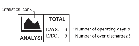
Statistical Data
To enter the following settings, in the Statistical Data screen press the Right arrow button.
Battery
Displayed parameter
Description
1
C-chg: OAH
Total amp hours produced
C-lod: OAH
Total amp hours consumed
E-chg: OKWH
Total power generated
E-lod: OKWH
Total power consumed
2
Rundays: 10D
Total number of operating days
LVD-Count: 0
Total number of over-discharges
FUL-Count: 0
Total number of full-charges
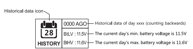
Historical Data
To enter the following settings, in the Historical Data screen press the Right arrow button.
Screen
Displayed parameter
Description
1
< History Data> xxxx Days Ago
xxxx: select the historical data of day xxxx (counting backwards)
0000: current day
0001: yesterday
0002: the day before yesterday
2
MinBatVol: 11.5V
The selected day’s min. battery voltage
MaxBatVol: 11.6V
The selected day’s max. battery voltage
MaxChgVol: OA
The selected day’s max. charging current
MaxLodVol: OA
The selected day’s max. discharge current
3
MaxChgPow: OW
The selected day’s max. generated power
MaxLodPow: OW
The selected day’s max. discharged power
C-D-Chg: OAH
The selected day’s total charged amp hours
C-D-Lod: OAH
The selected day’s total discharged amp hours
4
E-D-Chg: OKWh
The selected day’s total power generated
E-D-Lod: OKWh
The selected day’s total power consumed
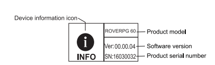
Device Information
To enter the following settings, in the Device Information screen press the Right arrow button.
Screen
Displayed parameter
Description
1
Model: ROVERPG 60
Controller model
HW-ver: 00.02.07
Hardware version
SW-ver: 00.00.04
Software version
Serial: 123456789
Controller serial number
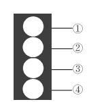
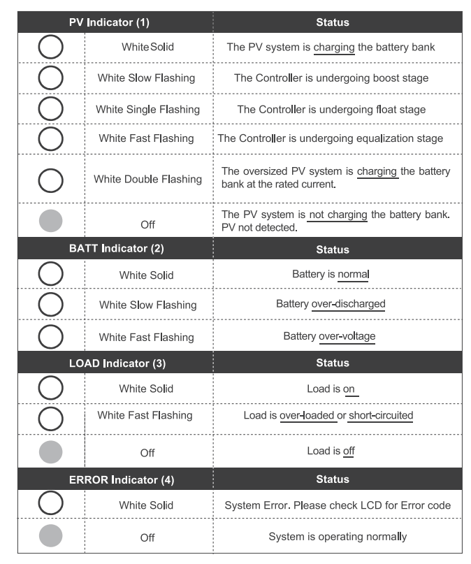
LED Indicators
(1)—PV array indicator
Indicating the controller's current charging mode.
(2)—BAT indicator
Indicating the battery's current state.
(3)—LOAD indicator
Indicating the loads' On/ Off state.
(4)—ERROR indicator
Indicating whether the controller is functioning normally.
Rover PG Protections
Protection
Behavior
PV Array Short Circuit
When PV shot circuit occurs, the controller will stop charging. Clear it to resume normal operation.
PV Overvoltage
If the PV voltage is larger than maximum input open voltage 150VDC, PV will remain disconnected until the voltage drops below 150VDC.
PV Overcurrent
The controller will limit the battery charging current to the maximum battery current rating. Therefore, an over-sized solar array will not operate at peak power.
Load Overload
If the current exceeds the maximum load current rating 1.05 times, the controller will disconnect the load. Overloading must be cleared up by reducing the load and restarting the controller.
Load Short Circuit
Fully protected against the load wiring short-circuit. Once the load short (more than quadruple rate current), the load short protection will start automatically. After 5 automatic load reconnect attempts, the faults must be cleared by restarting the controller.
PV Reverse Polarity
The controller will not operate if the PV wires are switched. Wire them correctly to resume normal controller operation.
Battery Reverse Polarity
The controller will not operate if the battery wires are switched. Wire them conecUy to resume normal controller operation.
Over-Temperature
If the temperature of the controller heat sink exceeds 65'C, the controller will automatically start the reducing the charging current and shut down when temperature exceeds 80 C.
System Status Troubleshooting
PV indicator
Troubleshoot
Off during daylight
Ensure that the PV wires are correctly and tightly secured inside the charge controller PV terminals. Use a multi-meter to make sure the poles are correctly connected to the charge controller.
BATT indicator
Troubleshoot
White Slow Flashing
Disconnect loads, if any, and let the PV modules charge the battery bank. Use a multi-meter to frequently check on any change in battery voltage to see if condition improves. This should ensure a fast charge. Otherwise, monitor the system and check to see if system improves.
White Fast Flashing
Using a multimeter check the battery voltage and verify it is not exceeding 32 volts.
Load indicator
Troubleshoot
White Fast Flashing
The Load circuit on the controller is being shorted or overloaded. Please ensure the device is properly connected to the controller and make sure it does not exceed 2QA (DC).
Error indicator
Troubleshoot
WhiteSolid
System Error. Please check LCD for Error code
Maintenance
Warning: Risk of Electric Shock! Make sure that all power is turned off before touching the terminals on the charge controller.
For best controller performance, it is recommended that these tasks be performed from time to time.
Check that controller is mounted in a clean, dry, and ventilated area.
Check wiring going into the charge controller and make sure there is no wire damage or wear.
Tighten all terminals and inspect any loose, broken, or burnt-up connections.
Make sure LED readings are consistent. Take necessary corrective action.
Check to make sure none of the terminals have any corrosion, insulation damage, high temperature, or any burnt/discoloration marks.
#1 I would like to buy this unit, I would to know if the unit come with the Bluetooth module or I have to buy it separately?
The BT-1 Bluetooth module is a separate item. It does come with a RS-232 to USB cable. You can download software for the PC. But if you want Bluetooth you need the BT-1. (It connects to the RS-232 port.)
#2 How would a positive ground controller be grounded and wired to loads on rv or boat?
Don't ground it, let it float, it should still be ok. Next time, buy a negative ground controller.... that's assuming your host rv or boat is set up for negative ground... then you can attach a wire on the ground lug of the controller to the "chassis" of your host vehicle although it is not necessary.
#3 What is the difference between the rover pg vs the rover li?
PG likely stands for Positive Ground ... (can not mount this to grounded metal in an RV for example ... the PG version works great in my rv (mounted inside) controlling two 100w panels in series) ... not sure what the li stands for. (tech support said that they only sell the PG version on Amazon, it costs less because it's not as main stream as a positive ground)