Loading ...
Loading ...
Loading ...
150
APPENDIX
APPENDIX
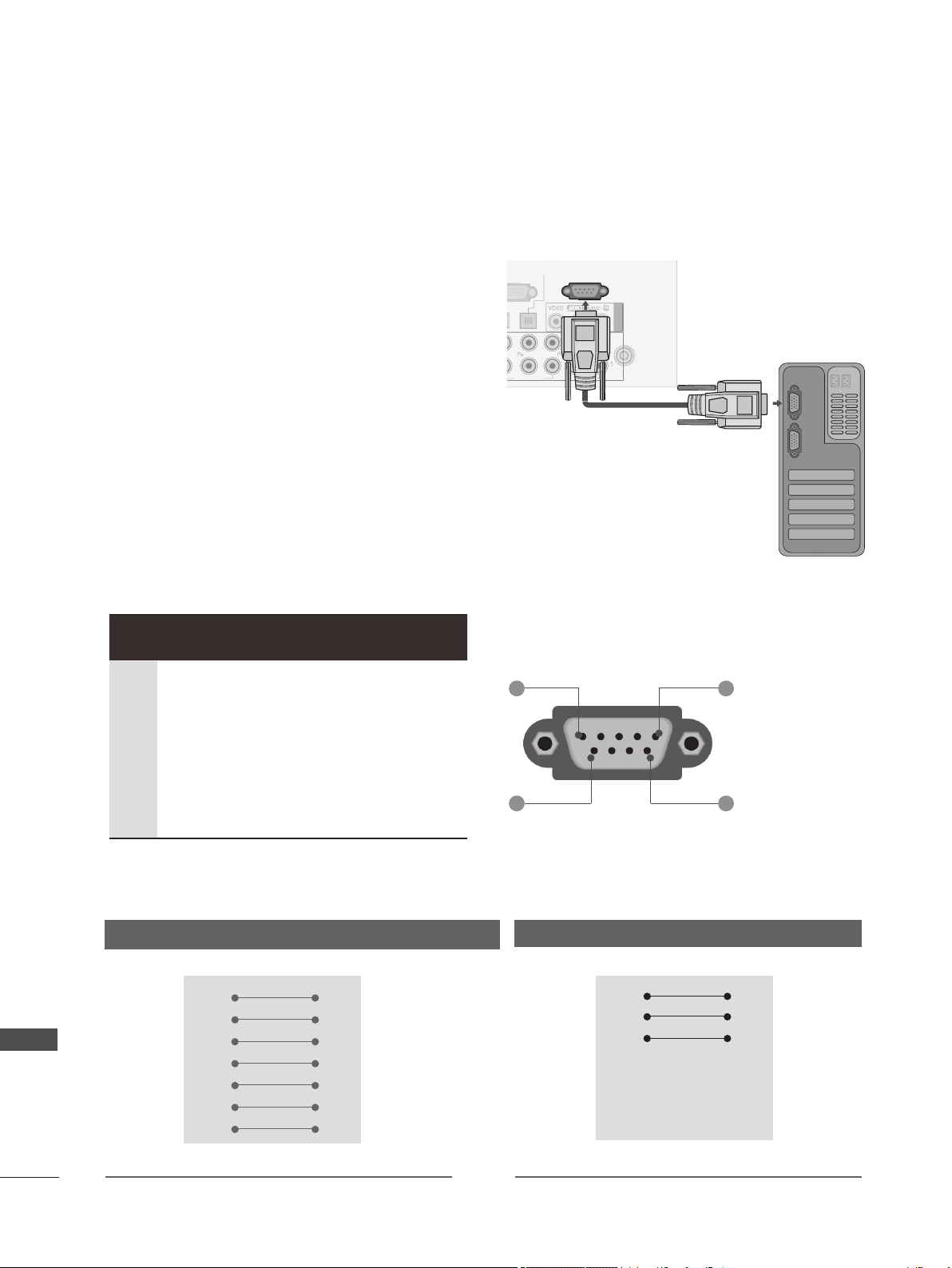
EXTERNAL CONTROL DEVICE SETUP
RS-232C Setup
Connect the RS-232C (serial port) input jack to an
external control device (such as a computer or an
A/V control system) to control the product’s func-
tions externally.
Connect the serial port of the control device to the
RS-232C jack on the product back panel.
Note: RS-232C connection cables are not supplied
with the product.
1 5
6 9
RS-232C Configurations
7-Wire Configurations
(
Standard RS-232C cable
)
PC TV
RXD 2 3 TXD
TXD 3 2 RXD
GND 5 5 GND
DTR 4 6 DSR
DSR 6 4 DTR
RTS 7 8 CTS
CTS 8 7 RTS
D-Sub 9 D-Sub 9
3-Wire Configurations
(
Not standard
)
PC TV
RXD 2 3 TXD
TXD 3 2 RXD
GND 5 5 GND
DTR 4 6 DTR
DSR 6 4 DSR
RTS 7 7 RTS
CTS 8 8 CTS
D-Sub 9 D-Sub 9
No. Pin Name
1
2
3
4
5
6
7
8
9
No connection
RXD
(
Receive data
)
TXD
(
Transmit data
)
DTR
(
DTE side ready
)
GND
DSR
(
DCE side ready
)
RTS
(
Ready to send
)
CTS
(
Clear to send
)
No Connection
RG
B IN
(PC)
( )
W
IRELE
SS
CO
NTR
O
L
O
PTI
C
AL
DI
G
ITA
L
A
UDIO OUT
1
2
AU
DI
O
V
IDE
O
LAN
/DVI IN
1
2
3
A
UDI
O
I
N
(RGB/DVI)
R
R
R
R
R
AUDIO
VIDEO
A
V IN
1
CO
MP
O
NENT I
N
RS-232C IN
(CONTROL & SERVICE)
ANTENNA
A
IN
Type of Connector; D-Sub 9-Pin Male
Loading ...
Loading ...
Loading ...