Loading ...
Loading ...
Loading ...
Westinghouse Portable Power | 19
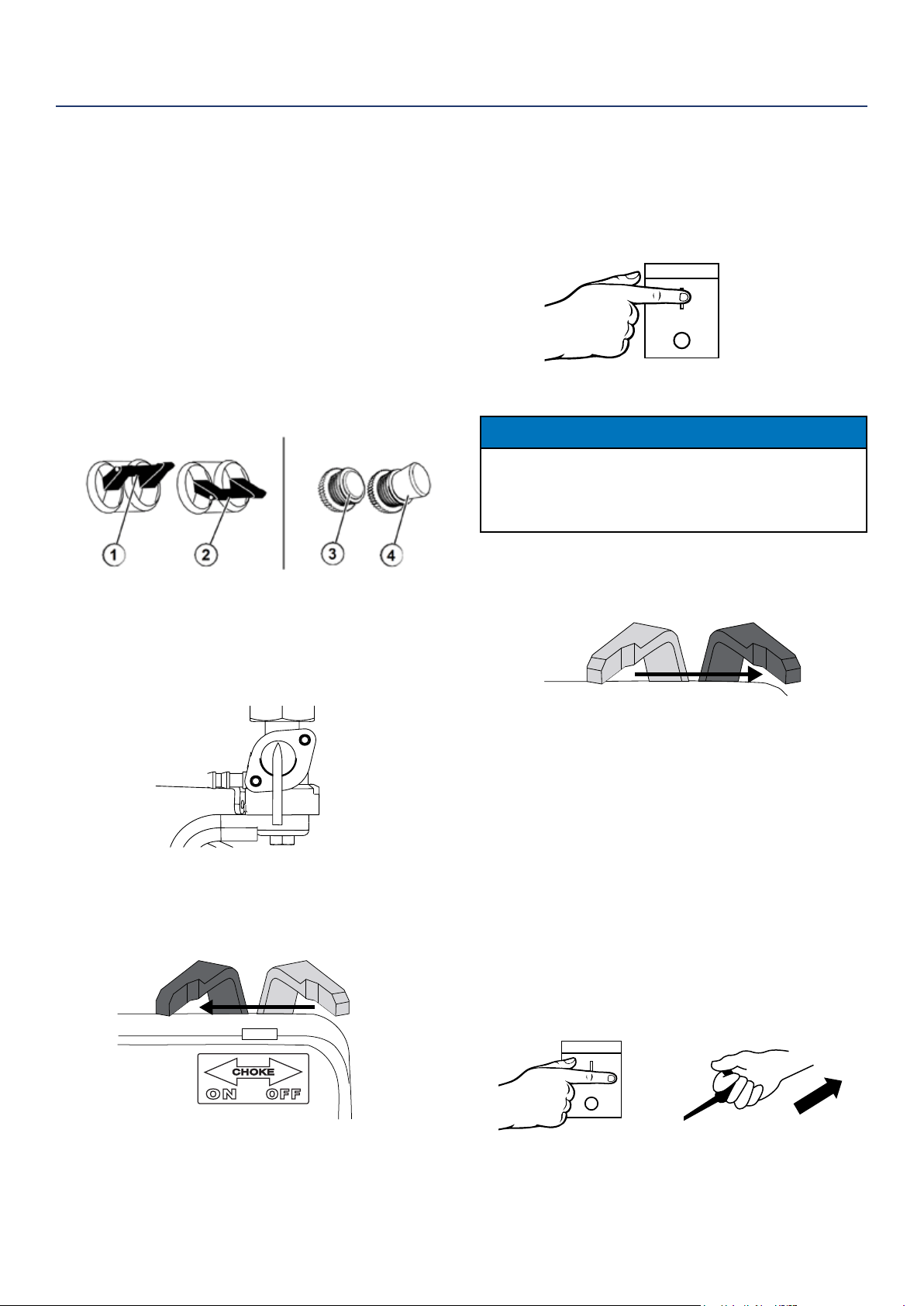
STARTING THE GENERATOR
1. Move generator to a at surface outside in a well
ventilated area away from open doors/windows.
2. Check oil levels (see Adding Engine Oil page 22).
3. Verify the battery is installed and both battery
cables are attached to their corresponding polarity.
(See Installing the Battery on page 11)
4. Disconnect all electrical loads from the generator.
5. Make sure the circuit breakers are properly set (see
Figure 7 below).
6. Move the fuel shut o valve to the ON position (see
Figure 8 below).
ON
OFF
Figure 8 - Fuel Shut O - ON
7. Move the choke lever to the ON position (see
Figure 9 below).
Figure 9 - Choke Lever - ON
8. Electric Start: Push and hold the engine control
switch in the START position until the engine starts.
Once the engine starts, release the engine control
switch; the switch will automatically move into the
RUN position (see Figure 10 below).
NOTICE
Failure to release the engine control switch once the engine starts
could result in damage to the generator.
Never push the engine control switch to the START position while
the engine is running’ this could damage the generator.
9. As the engine starts and stabilizes, gradually move
the choke lever back to the OFF position (see
Figure 11 below).
Note: If the engine fails to start after 5 seconds,
release the engine control switch. Let the generator
sit idle for 15 seconds and then repeat step 8. If
the cranking speed drops after each unsuccessful
attempt, then the battery may not be adequately
charged. Manually start the generator by following
steps below:
Manual Start: perform steps 1-7. Make sure the engine
control switch is in the RUN position. Firmly grasp and
pull the recoil handle slowly until you feel increased
resistance. At this point, apply a rapid pull while pulling
up and slightly away from the generator (see Figure
12). After engine starts wait 5 seconds and then move
choke to OFF.
OPERATION
Figure 10 - Engine Control Switch - START
Figure 12 - Engine Control Switch - RUN
Recoil Handle - PULL
Figure 11 - Choke Lever - OFF
Figure 7 - Breakers - (1) Operating Position,
(2) Tripped Position, (3) Operating Position,
(4) Tripped Position
START
RUN
STOP
START
RUN
STOP
Loading ...
Loading ...
Loading ...