Loading ...
Loading ...
Loading ...

DETAILED INSTALLATION INSTRUCTIONS
DRIVEN WELL (with check valve and well point)
1. Drive the well point into the ground according to the instructions
included with the well point. It must be deep enough to bore
through the water-bearing formation below the water table,
but it should not exceed 25 ft (7.6 m) in depth. An individual well
point may not supply the amount of water needed. Sometimes
it is necessary to use more than one well point to increase
the water supply. The two separate well points can be jointed
together using additional piping and a cross joint (see Typical
Installations, Figure 5).
2. Plan to have at least 1 ft (30 cm) of pipe protruding from
the ground. The rise pipe should be galvanized pipe in
approximately 5 ft (1.5 m) sections. This makes it easier to hand
drive. Use as much pipe and as many drive couplings as it takes
to both reach the water and account for the 1 ft (30 cm) of pipe
protruding from the ground.
3. Attach a 1-1/4" galvanized elbow onto the pipe protruding
from the ground.
4. Attach a 1-1/4" galvanized nipple to the 1-1/4" galvanized elbow.
5. Attach a 1-1/4" check valve to the 1-1/4" galvanized nipple.
6. Attach a 1-1/4" male PVC adapter to the 1-1/4" check valve.
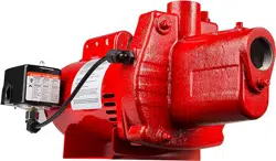
7. Install the pump in a clean, dry, and ventilated location that
provides adequate room for services and protection from
freezing temperatures. The pump should be bolted to a good
foundation, preferably concrete, and provided with adequate
drainage. Locating the pump as close as possible to the water
source reduces the friction in the suction pipe and will provide
maximum performance.
8. A pressure gauge is not supplied with the pump. It should be
installed into the 1/8" NPT hole on the front of the casing on the
opposite side of the pressure switch (see Typical Installations,
Figure 5).
9. Attach a 1-1/4" male galvanized adapter into the pump suction
inlet. Do not overtighten, as this could crack the fitting. Measure
from this adapter to the check valve that was installed in
Step 6. Cut 1-1/4" PVC pipe to this measurement. Using a round
file, smooth the pipe cutting. Ensure the pipe is clean and free
of any pipe shavings or pieces, as these could get into the pump
and may damage the impeller. Attach the 1-1/4" PVC pipe to the
adapter and then to the check valve. Check thoroughly for any
leaks. All connections and joints must be airtight. A pinhole
leak can prevent proper operation of the pump.
10. Driven well water levels may, at times, be too low to pump up.
To prevent damage to the pump, have an electrician replace the
pressure switch with a low pressure cut-o switch.
11. Follow the Pump to Tank Installation procedures.
12. Verify everything has been completed using the
Installation Checklist provided in this manual.
8
Loading ...
Loading ...
Loading ...