Loading ...
Loading ...
Loading ...
INTRODUCTION
The shallow well jet pump is ideal for the supply of fresh water to rural
homes, farms, and cabins. This pump is suitable for installations where the
vertical distance from the pump to the water level does not exceed 25 ft
(7.6 m), including drawdown (less at high altitudes). In oset installation,
friction losses in the suction pipe must be taken into consideration
(refer to Table 1, Friction Loss).
This instruction sheet provides you with the information required to
safely own and operate your product. Retain these instructions for
future reference.
The product you have purchased is of the highest quality workmanship and
material, and has been engineered to give you long and reliable service.
This product has been carefully tested, inspected, and packaged to ensure
safe delivery and operation. Please examine your item(s) carefully to
ensure that no damage occurred during shipment. If damage has occurred,
please contact the place of purchase. They will assist you in replacement or
repair, if required.
READ THESE INSTRUCTIONS CAREFULLY BEFORE ATTEMPTING TO INSTALL,
OPERATE OR SERVICE YOUR PRODUCT. KNOW THE PRODUCT’S APPLICATION,
LIMITATIONS, AND POTENTIAL HAZARDS. PROTECT YOURSELF AND OTHERS
BY OBSERVING ALL SAFETY INFORMATION. FAILURE TO COMPLY WITH
THESE INSTRUCTIONS COULD RESULT IN PERSONAL INJURY AND/OR
PROPERTY DAMAGE!
VOLTAGE SETTING INSTRUCTIONS
To change the pump voltage from the factory setting of 230 volts, a
qualified electrician should:
1. Disconnect the power supply to the pump.
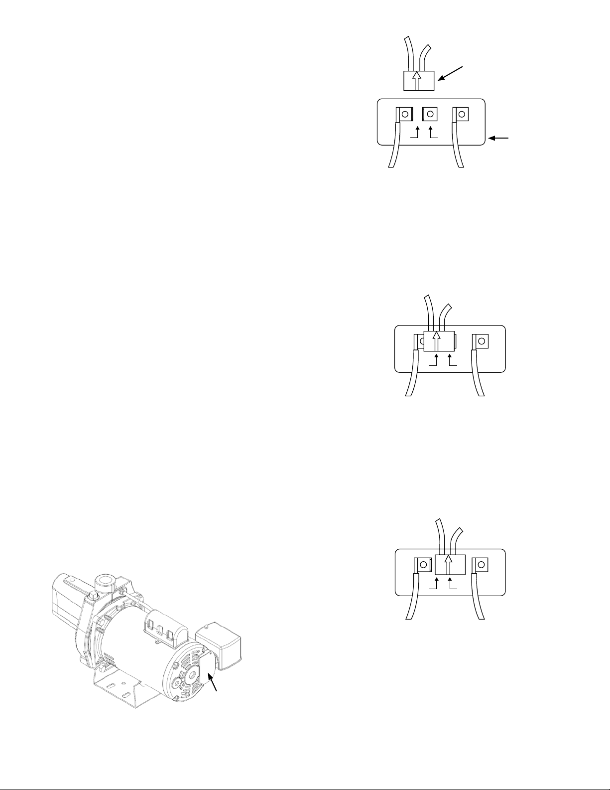
2. Remove the cover from the motor terminal box.
In #2, the motor's switch is set for 115 V. The black voltage change device
is pressed down onto both terminals with the white arrow on the voltage
change device pointing directly to the 115 V arrow on the terminal board.
#2 (Set to 115 V)
115 230
L2
L1
L2
L1
115 230
L2
L1
115230
Orange Brown
In #3, the motor's switch is set for 230 V. The black voltage change device is
pressed down onto only one terminal with the white arrow on the voltage
change device pointing directly to the 230 V arrow on the terminal board.
#3 (Set to 230 V)
115 230
L2
L1
L2
L1
115 230
L2
L1
115230
Orange Brown
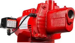
In #1, the motor's switch is shown before the black voltage change device is
pressed down onto the voltage terminals.
NOTE: DO NOT MOVE WHITE LEAD WIRES ON L1 & L2.
#1
115 230
L2
L1
L2
L1
115 230
L2
L1
115230
Terminal
Board
Voltage Change Device
Orange
Brown
Motor Terminal Box Cover
4
Loading ...
Loading ...
Loading ...