Loading ...
Loading ...
Loading ...
WIRING INSTRUCTIONS
s WARNING
!
ELECTRICAL PRECAUTIONS
All wiring, electrical connections, and system grounding must comply with the National Electrical Code (NEC) and with any local codes and ordinances.
Employ a licensed electrician.
s WARNING
!
RISK OF ELECTRICAL SHOCK
Before servicing motor-operated equipment, shut o the power at the main electrical panel and disconnect the power supply from motor and accessories.
Use safe working practices during servicing of equipment.
WIRING
An electrician should be employed to do the wiring and connect the
electrical service to the pump. The pressure switch is wired to the motor
at the factory, and the voltage for which the motor is wired is indicated by
the voltage change device (found under the wiring access cover located
on the back of the pump). Make sure the motor is wired for the same
voltage as the power supply. Refer to the inside of the wiring access cover
or this manual for voltage changing instructions. The power lines should be
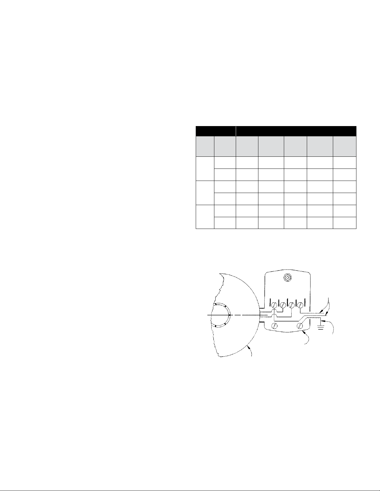
connected to the pressure switch terminals marked “Line”
(Figure 7). It is recommended that a separate circuit be led from the
distribution panel to the pump unit. A ground fault interrupter (GFI)
protected circuit should be used for all electrical devices operating near
water. Install a properly fused disconnect switch in the line, and make
certain the wiring is adequately sized and well-insulated. Undersized wire
between the motor and the power source will adversely limit the starting
and load carrying abilities of the motor. Minimum wire sizes for motor
branch circuits are recommended (see Table 2). For added safety, the pump
and motor should be grounded to the well casing, if metal, or the ground
in the distribution panel.
Motor Wire Gauge (AWG)
HP Volts
25 ft
(8 m)
50 ft
(15 m)
100 ft
(30 m)
150 ft
(46 m)
200 ft
(61 m)
1/2
115 14 14 12 10 8
230 14 14 14 14 14
3/4
115 14 14 10 8 8
230 14 14 14 14 12
1
115 14 12 10 8 6
230 14 14 14 14 12
Based on an approximate 3% voltage drop.
Table 2 - MAXIMUM WIRE LENGTH
Figure 7 - ELECTRICAL CONNECTIONS
Motor (Load)
Pressure Switch
Ground
Power Supply (Line)
L 1 L 2
11
Loading ...
Loading ...
Loading ...