INSTRUCTION MANUAL Pole Saw
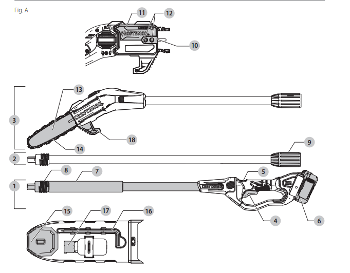
COMPONENTS
1 Handle assembly
2 Center extension pole
3 Saw head assembly
4 Trigger switch
5 Lock button
6 Battery
7 Foam gripper
8 Threaded pole
9 Threaded sleeve
10 Bar clamp
11 Sprocket cover
12 Hex head screws
13 Guide bar
14 Saw chain
15 Scabbard
16 Hex wrench
17 Oil bottle
18 Branch removal hook
WARNING: Read all safety warnings and all instructions. Failure to follow the warnings and instructions may result in electric shock, fire and/or serious injury.
WARNING: Never modify the product or any part of it. Damage or personal injury could result.
WARNING: To reduce the risk of injury, read the instruction manual.
Intended Use
- This pole saw is designed for household use.
- DO NOT use under wet conditions or in presence of flammable liquids or gases.
- DO NOT let children come into contact with the tool. Supervision is required when inexperienced operators use this tool.
ASSEMBLY AND ADJUSTMENTS
WARNING: To reduce the risk of serious personal injury, turn unit off and remove the battery pack before making any adjustments or removing/ installing attachments or accessories. An accidental start-up can cause injury
Installing and Removing Saw Chain
WARNING: Sharp moving blade. To prevent accidental operation, insure that battery is disconnected from the handle before performing the following operations. Failure to do this could result in serious personal injury.
CAUTION: Sharp moving blade. Always wear protective gloves when installing or removing the chain. The chain is sharp and can cut you when it is not running.
- Place the pole saw on a firm surface. Rotate the two hex head screws 12 counterclockwise with the hex wrench 16 provided.
- Remove sprocket cover 11 , bar clamp 10 , and hex head screws.
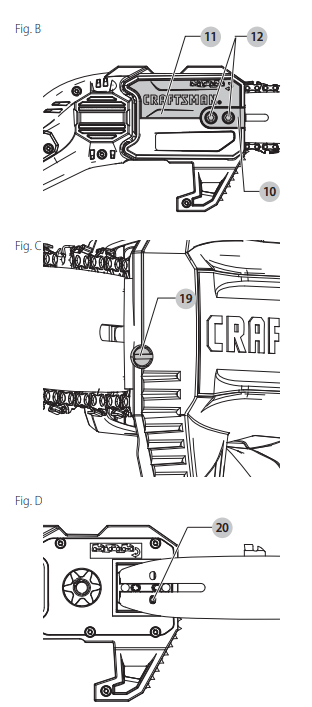
- To remove the saw chain 14 , rotate the screw 19 in the front of the housing using the flat screwdriver end of the wrench. Turning the screw counterclockwise allows the guide bar 13 to recede and reduces the tension on the chain so that it may be removed.
- Lift the worn saw chain out of the groove in the guide bar.
- Flip guide bar over.
- To replace the saw chain, check to make sure that the slot in the guide bar is over the location pins 20 shown in Figure D and that hole below the slot is located over the adjustment pin.
- Place new chain in groove of guide bar and around sprocket. Make sure saw teeth are facing correct direction by matching the graphic on housing or guide bar.
- Rotate the screw in the front of the housing clockwise to increase the chain tension.
- Replace sprocket cover, bar clamp, and hex head screws.
- Follow the instructions in the section Adjusting Chain Tension.
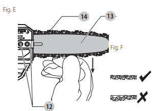
Adjusting Chain Tension (Fig. A, C, E, F)
- With the pole saw still on a firm surface check the saw chain 14 tension. The tension is correct when the saw chain snaps back after being pulled 1/8" (3 mm) away from the guide bar 13 with light force from the middle finger and thumb as shown in Figure E. There should be no “sag” between the guide bar and the saw chain on the underside as shown in Figure F.
- To adjust saw chain tension, loosen hex head screws 12 .
- Rotate the screw 19 in the front of the housing using the flat screwdriver end of the wrench.
- Do not over-tension the saw chain as this will lead to excessive wear and will reduce the life of the guide bar and saw chain. Overtensioning also reduces the amount of cuts you will get per battery charge.
- Once saw chain tension is correct, tighten hex head screws 12 to clamp bar.
- When the saw chain is new check the tension frequently (after disconnecting battery) during the first 2 hours of use as a new chain stretches slightly.
NOTE: Saw chain tension should be adjusted regularly
Chain Oiling (Fig. G)
- A high quality bar and chain oil or SAE30 weight motor oil should be used for saw chain 14 and guide bar 13 lubrication. The use of a vegetable based bar and chain oil is recommended when pruning trees. Mineral oil is not recommended because it may harm trees. Never use waste oil or very thick oil. These may damage your pole saw.
- Lubricate the whole saw chain evenly before each use as shown in Figure G. Also lubricate the saw chain whenever replacing a fully discharged battery with a fully charged one.

Transporting Pole Saw (Fig. A)
- Always remove the battery pack 6 from the handle and cover the saw chain 14 with the scabbard 15 when transporting the pole saw.
Joining Saw Head Module to HandleModule (Fig. H–K)

WARNING: Sharp moving blade. To prevent accidental operation, insure that battery is disconnected from the handle and that the protective scabbard is in place on the chain before performing the following operations. Failure to do this could result in serious personal injury.
The three assembliess which make up the pole saw are keyed to insure correct assembly. If an assembly does not smoothly attach to another do not force fit.
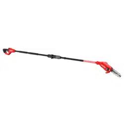
Combining the handle assembly 1 to the saw head assembly 3 creates a pole saw that is approximately 6' (1.8 m) in length as shown in Figure H.
To attach the handle assembly to the saw head assembly:
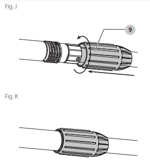
- Align the groove 21 on the outside of the coupling end of the handle assembly 1 with the tongue 22 on the inside of the coupling end of the saw head assembly 3 . Refer to Figure I. Push the two sections completely together. Refer to Figure J.
- Slide the threaded sleeve 9 on the saw head assembly down as far as possible and rotate the sleeve clockwise until it stops and completely covers the threads as shown in Figure K.
WARNING: Always check to make sure that the sleeve is completely threaded on and that the red threads are no longer visible. Not threading the sleeve completely on could result in the assemblys becoming disconnected creating a hazardous condition. Periodically check the connections to insure that no red threads are visible.
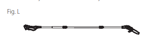
Joining Center Extension to Saw Head Module and Handle Module (Fig. A, L)
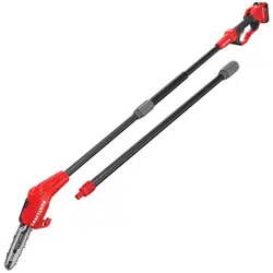
- Adding the center extension 2 to the handle assembly 1 and saw head assembly 3 creates a pole saw that is approximately 9' (2.7 m) in length as shown in Figure L. Refer to to Joining Saw Head Module to Handle Module for directions on how to attach the middle assembly to the handle assembly and saw head assembly.
- WARNING: Always check to make sure that the sleeve is completely threaded on and that the red threads are no longer visible. Not threading the sleeve completely on could result in the assemblys becoming disconnected creating a hazardous condition. Periodically check the connections to insure that no red threads are visible.
DISASSEMBLY
WARNING: To reduce the risk of serious personal injury, turn unit off and remove the battery pack before making any adjustments or removing/ installing attachments or accessories. An accidental start-up can cause injury.
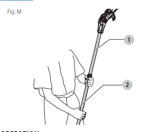
Detaching Saw Head Module (Fig. M)
- WARNING: Sharp moving blade. To prevent accidental operation, insure that battery is disconnected from the handle and that the protective scabbard is in place on the chain before performing the following operations. Failure to do this could result in serious personal injury.
- When detaching the assemblies, whether it is in the two assembly or three assembly mode, always detach the saw head assembly 1 first. To do this, rest the handle assembly 2 on the ground and grasp the center of the saw head assembly with one hand as shown in Figure M. Use your other hand to loosen the threaded sleeve and then pull the two halves apart. Repeat this process if the center extension was attached.
OPERATION
WARNING: To reduce the risk of serious personal injury, turn unit off and remove the battery pack before making any adjustments or removing/ installing attachments or accessories. An accidental start-up can cause injury.
Installing and Removing the Battery Pack (Fig. N)
- NOTE: For best results, make sure your battery pack is fully charged.
- To install the battery pack 6 into the tool handle, align the battery pack with the rails inside the tool’s handle and slide it into the handle until the battery pack is firmly seated in the tool and ensure that it does not disengage. To remove the battery pack from the tool, press the release button 22 and firmly pull the battery pack out of the tool handle. Insert it into the charger as described in the charger section of this manual.

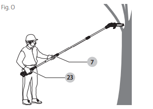
Proper Hand Position (Fig. O)
- WARNING: To reduce the risk of serious personal injury, ALWAYS use proper hand position as shown.
- WARNING: To reduce the risk of serious personal injury, ALWAYS hold securely in anticipation of a sudden reaction.
- Proper hand position requires one hand on the main handle 23 and one hand on the foam gripper 7
Operating the Pole Saw (Fig. A)
- Failure to follow all instructions listed below may result in electric shock, fire and/or serious personal injury.
- CAUTION: Always reduce the tension off the chain again after finishing work. The chain contracts as it cools down. If it is not slackened off, it can damage the pole saw.
- IMPORTANT: Never operate a pole saw that is damaged or improperly adjusted or that is not completely and securely assembled. Be sure that the saw chain 14 stops moving when the trigger switch is released. Never adjust the guide bar 13 or saw chain when the motor is operating or the battery is attached.
Pole Saw Trimming/Pruning
WARNINGS:
- Never stand directly under the limb you are cutting. Always position yourself out of the path of falling debris.
- Always wear head, eye, foot and body protection. Wearing body protection helps reduce the risk of injury when operating this unit.
- Never stand on a ladder or other unstable support while using the pole saw. Always avoid any position which can cause you to loose your balance and cause severe injury.
- Keep other persons at least 50' (15 m) from the work area. Distractions can cause you to lose control.
- Electrocution Hazard. To prevent shock, do not operate within 50' (15 m) of overhead electrical lines. Always check surrounding area for hidden electrical lines.
- Do not extend pole saw switch handle above shoulder height.
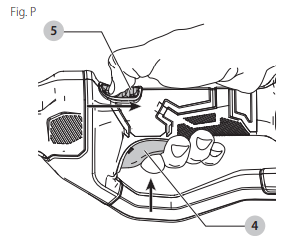
On/Off Switch (Fig. P)
- Always be sure of your footing and grip the pole saw firmly with both hands with the thumb and fingers encircling the handle. To turn the tool ON pull the lock button 5 back with your thumb and then squeeze the trigger switch 4 with your fingers as shown in Figure P. (Once the tool is running you can release the lock button.) To turn the tool OFF, release the trigger.
Branch Removal Hook (Fig. A)
- CAUTION: The branch removal hook is not a belt hook. To hang the tool on the Versatrack trackwall rail, use the integral hang hook. Refer to the Versatrack™ section for further information.
- Your pole saw includes a branch removal hook 18 for the intended purpose of helping to remove small to moderately sized pruned branches.
Pruning With the Pole Saw (Fig. A, O, Q)
WARNING: Let the tool work at its own pace. Do not overload.
WARNING: When pruning trees: guard against kickback which can result in severe injury or death. See Guard Against Kickback, to avoid the risk of kickback. Do not overreach. Make sure your footing is firm. Keep feet apart. Divide your weight evenly on both feet.
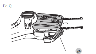
- Use both hands to grip pole saw as shown in Figure O. Use a firm grip. Thumbs and fingers must wrap around pole saw handle and pole. Keep fingers away from sawdust exhaust chute 24 shown in Figure Q.
- Never operate while in a tree, in any awkward position or on a ladder or other unstable surface. You may lose control of pole saw causing severe injury.
- Follow directions below to trim a tee.
- Make sure pole saw is running at full speed before making a cut. When starting a cut, place moving saw chain 14 against limb. Hold pole saw firmly in place to avoid possible bouncing or skating (sideways movement) of pole saw.
- Guide pole saw using light pressure. Make first cut 6" (152 mm) from tree trunk on underside of limb. Use top of guide bar 13 to make this cut. Cut 1/3 through diameter of limb. Then make the finish cut from the top. If you try to cut off thick branches from the bottom, the branch may close in and pinch the saw chain in the cut. If you try to cut off thick branches from the top, without a shallow undercut, the branch may splinter. Do not force pole saw. The motor will overload and can burn out. It will do the job better and safer at the rate for which it was intended.
- Remove pole saw from cut while it is running at full speed. Stop pole saw by releasing trigger switch 4 . Make sure saw chain has stopped before setting pole saw down.
Auto-Stop Chain Braking System
- Your pole saw is fitted with an auto-stop chain braking system which will stop the chain quickly each time you release the rear trigger, or if kickback should occur. This system should be tested before every use.
Saw Chain Sharpness
- CAUTION: Sharp chain. Always wear protective gloves when handling the chain. The chain is sharp and can cut you when it is not running.
- IMPORTANT: The chain cutters will dull immediately if they touch the ground, stones, masonry or a nail while cutting.
- To get the best possible performance from your chain saw it is important to keep the teeth of the saw chain sharp. Chain sharpening services are available from your nearest CRAFTSMAN service center.
- NOTE: Each time the saw chain is sharpened, it loses some of the reduced kickback qualities and extra caution should be used. It is recommended that a saw chain be sharpened no more than four times.
MAINTENANCE
- WARNING: To reduce the risk of serious personal injury, turn unit off and remove the battery pack before making any adjustments or removing/ installing attachments or accessories. An accidental start-up can cause injury.
- Regular maintenance ensures a long effective life for the tool. After every 10 minutes of use be sure to remove the battery (be aware the chain and bar can be hot!) check the bar and chain for correct tension and lubricate per Adjusting Chain Tension and Chain Oiling.
Accessories
- WARNING: Since accessories, other than those offered by CRAFTSMAN, have not been tested with this product, use of such accessories with this tool could be hazardous. To reduce the risk of injury, only CRAFTSMAN recommended accessories should be used with this product.
- Recommended accessories for use with your tool are available at extra cost from your local dealer or authorized service center. If you need assistance in locating any accessory, please contact CRAFTSMAN, call 1-888-331-4569.
Versatrack™ (Fig. R)
- WARNING: To reduce the risk of serious personal injury, turn unit off and remove the battery pack before making any adjustments or removing/ installing attachments or accessories. An accidental start-up can cause injury.
- WARNING: To reduce the risk of serious personal injury, do not use a damaged Versatrack™ integral hang hook or Versatrack™ Trackwall. A damaged Versatrack™ integral hang hook or Versatrack™ Trackwall will not support the weight of the tool.
- WARNING: To reduce the risk of serious personal injury, DO NOT suspend tool overhead or suspend objects from the integral hang hook. ONLY suspend tool on the Versatrack™ Trackwall using the integral hang hook.
- WARNING: The Versatrack™ integral hang hook is intended to mount the tool onto a Versatrack™ Trackwall rail. Do not use the integral hang hook to mount the tool to any other surface.
- WARNING: The Versatrack™ integral hang hook is not a belt hook.
- WARNING: When hanging objects on a Versatrack™ Trackwall rail, adequately space the tools in order to not exceed 75 lb (35 kg) per linear foot.
- WARNING: Before using the tool make sure that the Versatrack™ integral hang hook is returned to its original position
- IMPORTANT: Versatrack™ accessories mount compatible tools securely to the Versatrack™ Trackwall system.
1. Turn tool off, remove the battery pack and remove accessories.
CAUTION: Any product with exposed cutting teeth must have them covered securely if it is to be on the Versatrack™ Trackwall.
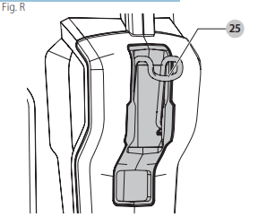
2. Flip or pull open the integral hang hook 25 . It clicks when locked into position.
3. Mount the integral hang hook to the Versatrack™ Trackwall.
NOTE: Versatrack™ accessories for use with your tool are available at extra cost from your local dealer or authorized service center. If you need assistance in locating any accessory, please contact CRAFTSMAN, call 1-888-331-4569.
Cleaning
- WARNING: Blow dirt and dust out of all air vents with clean, dry air at least once a week. To minimize the risk of eye injury, always wear ANSI Z87.1 approved eye protection when performing this procedure.
- WARNING: Never use solvents or other harsh chemicals for cleaning the non-metallic parts of the tool. These chemicals may weaken the plastic materials used in these parts. Use a cloth dampened only with water and mild soap. Never let any liquid get inside the tool; never immerse any part of the tool into a liquid.
Repairs
- The charger and battery pack are not serviceable. There are no serviceable parts inside the charger or battery pack.
- WARNING: To assure product SAFETY and RELIABILITY, repairs, maintenance and adjustment (including brush inspection and replacement, when applicable) should be performed by a CRAFTSMAN factory service center or a CRAFTSMAN authorized service center. Always use identical replacement parts.
TROUBLESHOOTING GUIDE
BE SURE TO FOLLOW SAFETY RULES AND INSTRUCTIONS
For assistance with your product, visit our website at www.craftsman.com for a list of service centers, or call CRAFTSMAN at 1-888-331-4569.
| PROBLEM |
POSSIBLE CAUSE |
SOLUTION |
| Unit will not start. |
Battery pack not installedproperly.
Battery pack not charged.
Lock button not actuated
Pole connections not properly tightened.
|
Check battery pack installation.
Check battery pack charging requirements.
Pull back on lock button/actuate trigger.
Refer to Joining Saw Head Module to Handle Module
|
| Battery pack will not charge. |
Battery pack not inserted into charger.
Charger not pluggedin.
Surrounding air temperature too hot or too cold
|
Insert battery pack into charger until LED illuminates
Plug charger into a working outlet. Refer to Important Charging Notes for moredetails.
Move battery pack to a surrounding air temperature of above 40°F (4.5 °C) or below 104 °F (+40 °C).
|
| Bar/chain overheated. |
Chain too tight
Lubrication needed.
|
Refer to Adjusting Chain Tension
Refer to Chain Oiling
|
| Chain is loose. |
Chain tension set incorrectly. |
Refer to Adjusting Chain Tension. |
| Poor cut quality |
Chain tension set incorrectly
Chain needs replacement
|
Refer to Adjusting Chain Tension. NOTE: Excessive tension leads to excessive wear and reduction in life of bar & chain. Lubricate after every 10 minutes of use.
Refer to Installing and Removing Saw Chain
|
| Unit runs but does not cut. |
Chain installed backwards. |
Refer to Installing and Removing Saw Chain |