User Guide
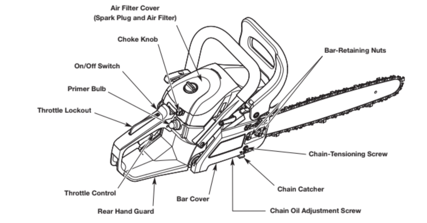
KNOW YOUR UNIT
APPLICATION
• Felling and limbing trees
• Cutting logs (bucking)
• Pruning trees
ASSEMBLY TOOLS REQUIRED
• Flat-head screwdriver or multi-purpose tool (provided)
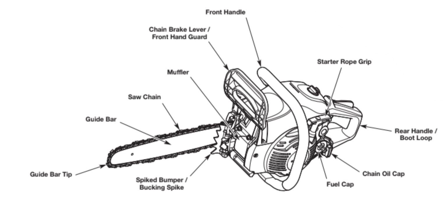
ESSENTIAL TERMS AND DENIFITIONS
• CHAIN SAW - A tool designed to cut wood with a saw chain. A chain saw is an integrated unit comprised of a power source, saw chain, guide bar, and handles that are designed to be held by two hands during operation.
• CHAIN SAW POWERHEAD - A chain saw without the saw chain and guide bar.
• DRIVE SPROCKET - A toothed wheel that drives the saw chain.
• FRONT HANDLE - A support handle located toward the front of the chain saw.
• REAR HANDLE - A support handle located toward the rear of the chain saw.
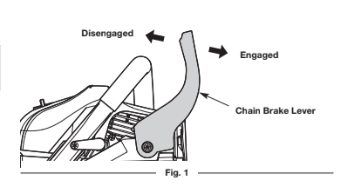
• CHAIN BRAKE LEVER / FRONT HAND GUARD - A structural barrier between the front handle and the guide bar. The front hand guard helps protect the operator’s left hand if it slips off the front handle while the unit is running. The chain brake lever is also used to manually engage the chain brake.
• CHAIN BRAKE - A device that reduces the chance of injury if kickback occurs, by stopping the saw chain in milliseconds. The chain brake is designed to engage automatically in response to kickback. The chain brake can also be activated by pushing the chain brake lever forward, either intentionally or if the operator’s hand strikes the lever during kickback.
• REAR HAND GUARD - A structural barrier below the rear handle. The rear hand guard helps protect the operator’s right hand if the saw chain breaks or disengages from the guide bar during operation.
• GUIDE BAR - A solid railed structure that supports and guides the saw chain.
• GUIDE BAR TIP - The tip or end of the guide bar.
• REDUCED-KICKBACK GUIDE BAR - A guide bar that has been demonstrated to reduce kickback significantly.
• SAW CHAIN - A loop of chain with teeth designed to cut wood, which is driven by the engine and is supported by the guide bar. The saw chain is composed of drive links, cutters and side links, held together by rivets.
• LOW-KICKBACK SAW CHAIN - A saw chain that complies with the kickback performance requirements of ANSI/OPEI B175.1-2012 when tested on a representative sample of chain saws. Low-kickback saw chain significantly reduces the chance of kickback and the intensity of kickback, due to specially designed depth gauges and guard links.
• REPLACEMENT SAW CHAIN - A saw chain that complies with the kickback performance requirements of ANSI/OPEI B175.1-2012 when tested with specific chain saws. It may not meet the ANSI/OPEI performance standards when used with other chain saws.
• SPIKED BUMPER - The pointed tooth (or teeth), at the front of the chain saw, used during felling and bucking to help pivot the saw and maintain a stable position while cutting.
• CHAIN CATCHER - A device designed to intercept a whipping chain. The chain catcher reduces the chance of injury if the saw chain breaks or disengages from the guide bar during operation.
• OILER CONTROL - A system for oiling the saw chain and guide bar.
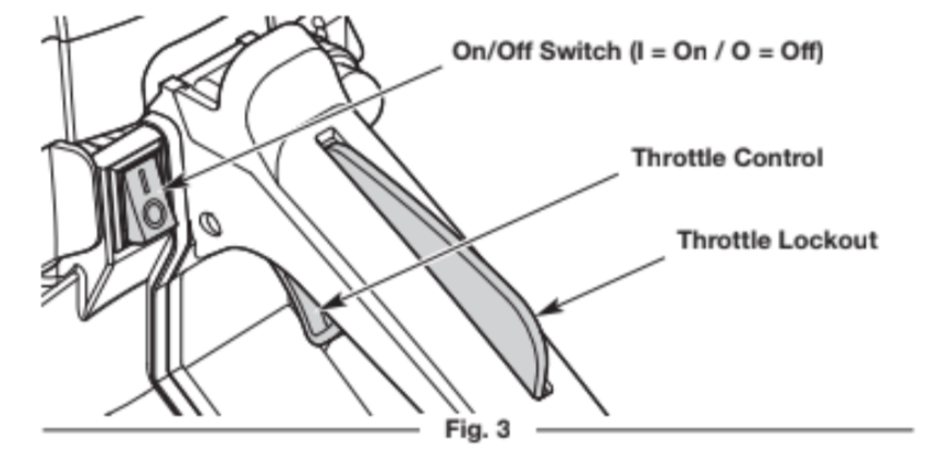
• ON/OFF SWITCH - A device that immediately stops the engine when moved to the OFF position. The saw chain will then coast to a stop. The On/Off switch must be moved to the On position to start the engine.
• THROTTLE CONTROL - A device used in conjunction with the throttle lockout to accelerate the engine. Releasing the throttle control returns the engine to idle.
• THROTTLE LOCKOUT - A device that prevents accidental acceleration of the engine. The throttle control cannot be squeezed unless the throttle lockout is engaged.
• SPARK ARRESTER SCREEN - A device that retains carbon and other flammable particles over 0.023 inches (0.6mm) in size from the engine exhaust flow. Compliance with local, state and federal laws and/or regulations governing the use of a spark arrester screen is the user’s responsibility. Refer to Spark Arrestor Note in the Safety section for additional information.
• KICKBACK - A sudden backward and/or upward motion of the guide bar and saw chain. Kickback can occur if the upper portion of the guide bar tip touches an object while the saw chain is spinning (rotational kickback). Kickback can also occur if the wood closes in and pinches the saw chain inside the cut (linear kickback).
• ROTATIONAL KICKBACK - A sudden backward and upward motion of the guide bar and saw chain. Rotational kickback can occur if the upper portion of the guide bar tip touches an object while the saw chain is spinning. The guide bar and saw chain are then kicked up and back toward the operator in a lightning-fast reverse reaction.
• LINEAR KICKBACK (PINCH KICKBACK) - A sudden backward motion of the guide bar and saw chain. Linear (pinch) kickback can occur if the wood closes in and pinches the saw chain inside a cut. The saw is then sent straight back toward the operator.
• NORMAL CUTTING POSITION - The positions assumed while making bucking and felling cuts.
• FELLING - The process of cutting down a tree.
• NOTCHED UNDERCUT - The first cutting procedure in the tree felling process. A notch is cut on one side of the tree to direct its fall.
• FELLING BACK CUT - The final cut in the tree felling process. The felling back cut is made on the opposite side of the tree from the notched undercut.
• BUCKING - The process of cutting a felled tree or log into lengths.
• LIMBING - The process of removing branches from a fallen tree.
• PRUNING - The process of cutting limbs from a living tree.
SPECIFICATION
Engine Type . . . . . . . . . . . . . . . . . . . . . . . . . . . . . . . . . . . . . . . . . . . . . . . . . . . . . . . . . . . . . . .Air-Cooled, 2-Cycle
Displacement. . . . . . . . . . . . . . . . . . . . . . . . . . . . . . . . . . . . . . . . . . . . . . . . . . . . . . . . . . . . . . ..42 cc (2.56 cu. in.)
Spark Plug Gap. . . . . . . . . . . . . . . . . . . . . . . . . . . . . . . . . . . . . . . . . . . . . . . . . . . . . . . . . . . .0.025 in. (0.635 mm)
Spark Plug . . . . . . . . . . . . . . . . . . . . . . . . . . . . . . . . . . . . . . . . . . . . . . . . . . Champion® RZ7C or equivalent plug
Lubrication . . . . . . . . . . . . . . . . . . . . . . . . . . . . . . . . . . . . . . . . . . . . . . . . . . . . . . . . . . . . . . . . . Bar and Chain Oil
Fuel/Oil Ratio . . . . . . . . . . . . . . . . . . . . . . . . . . . . . . . . . . . . . . . . . . . . . . . . . . . . . . . . . . . . . . . . . . . . . . . . . . 40:1
Fuel Tank Capacity . . . . . . . . . . . . . . . . . . . . . . . . . . . . . . . . . . . . . . . . . . . . . . . . . . . . . . . . . . . . . .9 oz. (270 mL)
Chain Oil Reservoir Capacity . . . . . . . . . . . . . . . . . . . . . . . . . . . . . . . . . . . . . . . . . . . . . . . . . . . . 6.5 oz. (200 mL)
Approximate Unit Weight (without fuel or chain oil) . . . . . . . . . . . . . . . . . . . . . . . . 11.75 - 12.75 lbs. (5.3 - 5.8 kg)
Guide Bar Length (S145 / CMXGSAMNN4214) . . . . . . . . . . . . . . . . . . . . . . . . . . . . . . . . . . . . . . .14 in. (35.6 cm)
Guide Bar Length (S160 / CMXGSAMNN4216) . . . . . . . . . . . . . . . . . . . . . . . . . . . . . . . . . . . . . . .16 in. (40.6 cm)
Guide Bar Length (S180 / CMXGSAMCX4218). . . . . . . . . . . . . . . . . . . . . . . . . . . . . . . . . . . . . . . 18 in. (45.7 cm)
Saw Chain Pitch . . . . . . . . . . . . . . . . . . . . . . . . . . . . . . . . . . . . . . . . . . . . . . . . . . . . . . . . . . . . . . .3/8 in. (9.5 mm)
Saw Chain Gauge . . . . . . . . . . . . . . . . . . . . . . . . . . . . . . . . . . . . . . . . . . . . . . . . . . . . . . . . . . . 0.050 in. (1.3 mm)
* All specifications are based on the latest product information available at the time of printing. We reserve the right to make changes at any time without notice.
REPLACEMENT PARTS
Please contact the Customer Support Department to order replacement parts.
Part # Description
713-05277 . . . . . . . . . . . . . . . . . . . . . . . . . . . . . . . . . . . . . . . . . . . . . . . .Saw Chain (14 in. / 35.6 cm)
713-05276 . . . . . . . . . . . . . . . . . . . . . . . . . . . . . . . . . . . . . . . . . . . . . . . .Saw Chain (16 in. / 40.6 cm)
713-05042 . . . . . . . . . . . . . . . . . . . . . . . . . . . . . . . . . . . . . . . . . . . . . . . .Saw Chain (18 in. / 45.7 cm)
795-00782 . . . . . . . . . . . . . . . . . . . . . . . . . . . . . . . . . . . . . . . . . . . . . . . .Guide Bar (14 in. / 35.6 cm)
795-00542 . . . . . . . . . . . . . . . . . . . . . . . . . . . . . . . . . . . . . . . . . . . . . . . .Guide Bar (16 in. / 40.6 cm)
795-00543 . . . . . . . . . . . . . . . . . . . . . . . . . . . . . . . . . . . . . . . . . . . . . . . .Guide Bar (18 in. / 45.7 cm)
753-08105 . . . . . . . . . . . . . . . . . . . . . . . . . . . . . . . . . . . . . . . . . . . . . . . .Bar-Retaining Nuts
ASSEMBLY
ADDING BAR AND CHAIN OIL: INITIAL USE
This unit comes from the factory with the chain oil reservoir empty.
Fill the chain oil reservoir with bar and chain oil before starting or using the unit. Refer to Adding Bar and Chain Oil instructions in the Maintenance section.
ADJUSTING THE CHAIN TENSION: INITIAL USE
The saw chain must be properly tensioned before attempting to start or operate the unit. The saw chain may also require additional tensioning as the saw chain heats up during operation. Refer to Adjusting the Chain Tension instructions in the Maintenance section.
TESTING THE CHAIN BRAKE
WARNING: Always activate the chain brake slowly anddeliberately. Keep the saw chain from touching anything. Do not let the chain saw tip forward.
Always test the chain brake before using the unit.
1. Set the unit on a flat, level surface.
2. Make sure the chain brake lever is pulled back in the disengaged position (Fig. 1).
3. Start the unit. Refer to Starting Instructions in the Starting and Stopping section. Maintain a proper grip. Refer to Holding the Unit in the Operation section.
4. While the unit is running, squeeze the throttle control to 1/3 throttle and then engage the chain brake by pushing the chain brake lever forward with the left hand (Fig. 1). The chain should stop moving abruptly.
- IF... If the chain stops moving, the chain brake is working correctly.
- IF... If the chain does not stop moving, have the unit serviced by an authorized service dealer.
5. Stop the engine and return the chain brake to the disengagedposition. Refer to Stopping Instructions in the Starting and Stopping section.
OIL AND FUEL
OIL AND FUEL MIXING INSTRUCTIONS
The use of old and/or improperly mixed fuel is the most common cause of performance problems. Use only fresh, clean unleaded gasoline.
Follow the instructions carefully for the proper gasoline/oil mixture.
Denifition of Blended Fuels
Today's fuels are often a blend of gasoline and oxygenates such as ethanol, methanol or MTBE (ether). Alcohol-blended fuel absorbs water. As little as 1% water in the fuel can make fuel and oil separate, forming acids when stored. ALWAYS use fresh fuel (less than 30 days old).
NOTE: Dispose of old fuel according to federal, state and local regulations.
Using Blended Fuels
If using a blended fuel:
• Always use the fresh fuel mix explained in this operator's manual
• Use the fuel additive STA-BIL® or an equivalent
• Always agitate the fuel mix before fueling the unit
CAUTION: DO NOT USE E85 FUEL IN THIS UNIT. It has been proven that fuel containing greater than 10% ethanol will likely damage this engine and void the warranty.
Using Fuel Additives
The container of 2-cycle oil provided with this unit includes a fuel additive to help inhibit corrosion and minimize gum deposits. Always use the brand of 2-cycle oil that came with this unit. If this is unavailable, use a 2-cycle oil designed for air-cooled engines and mix it with a fuel additive, such as STA-BIL Fuel Stabilizer or an
equivalent. Add 0.8 oz. (23 ml) of fuel additive per gallon of fuel, according to the instructions on the container. NEVER add fuel additives directly to the unit's fuel tank.
Mixing the Fuel
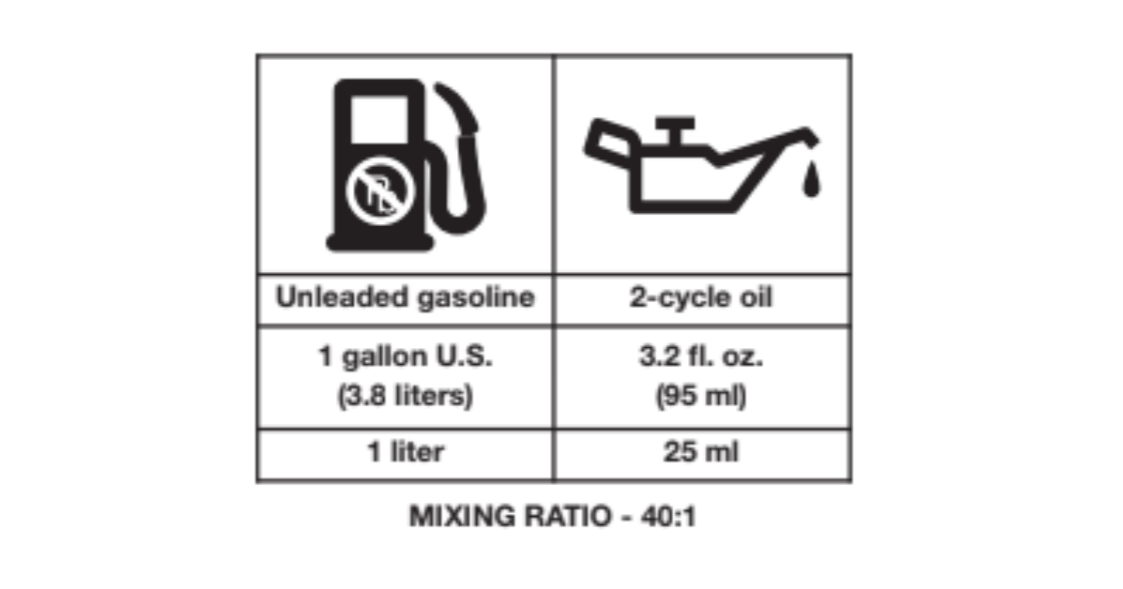
NOTE: This unit comes with a 3.2 oz. (95 ml) container of 2-cycle oil. To obtain the correct fuel mixture described below, pour the entire container into one gallon of unleaded gasoline.
CAUTION: For proper engine operation and maximumreliability, pay strict attention to the gasoline and oil mixing instructions on the 2-cycle oil container. Using improperly mixed fuel can severely damage the engine.
Thoroughly mix the proper ratio of unleaded gasoline with 2-cycle engine oil. Do not mix them directly in the unit’s fuel tank. Use a separate fuel can. Use a 40:1 gasoline/oil ratio. See the table below for specific gasoline and oil mixing ratios.
FUELING THE UNIT
WARNING: Gasoline is extremely flammable. Ignited vapors may explode. Always stop the engine and allow it to cool before filling the fuel tank. Do not smoke while filling the tank. Keep sparks and open flames at a distance from the area.
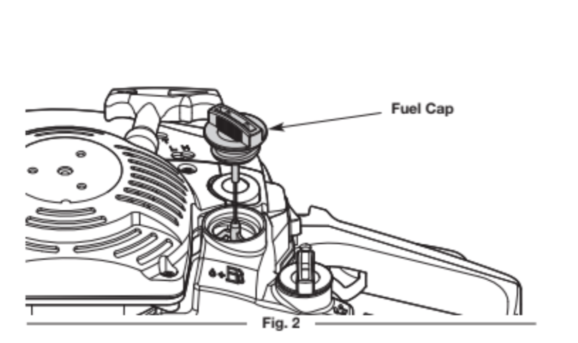
WARNING: Remove the fuel cap slowly to avoid injury from fuel spray. Never operate the unit without the fuel cap securely in place.
WARNING: Add fuel in a clean, well-ventilated outdoor area. Wipe up any spilled fuel immediately. Avoid creating a source of ignition for spilled fuel. Do not start the engine until fuel vapors dissipate.
1. Position the unit with the fuel cap facing up.
2. Slowly remove the fuel cap (Fig. 2).
3. Place the fuel container spout into the fuel tank fill hole and fill the tank.
NOTE: Do not overfill the tank.
4. Wipe up any fuel that may have spilled.
5. Reinstall the fuel cap.
6. Move the unit at least 30 ft. (9.1 m) from the fuel container and the fueling site before starting the engine.
STARTING AND STOPPING
WARNING: Operate this unit only in a well-ventilated outdoor area. Carbon monoxide exhaust fumes can be lethal in a confined area.
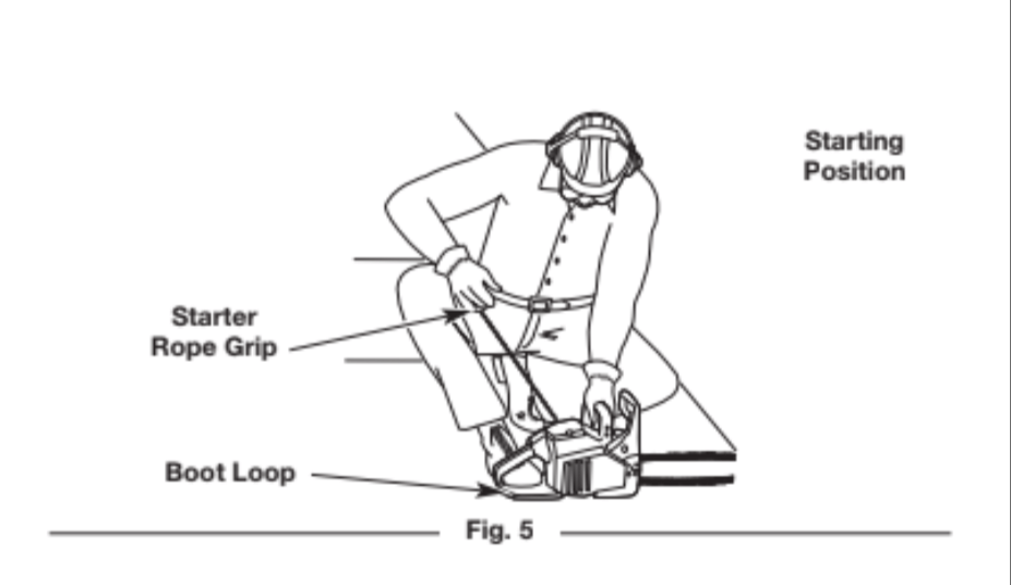
WARNING: Avoid accidentally starting the unit. To avoid serious injury, the operator and the unit must be in a stable position when pulling the starter rope (Fig. 5).
WARNING: Never operate the unit without the guide bar and saw chain properly installed. Make sure the bar-retaining nuts are tight and the guide bar cover is securely assembled. Make sure the saw chain is properly tensioned. Refer to Adjusting the Chain Tension instructions in the Maintenance section.
WARNING: The saw chain will spin after the engine starts. Keep hands and feet clear of the saw chain and do not allow the saw chain to contact any object(s).
STARTING INSTRUCTIONS
Before Starting the Unit
1. Mix gasoline with oil. Refer to Oil and Fuel Mixing Instructions.
2. Fill the fuel tank. Refer to Fueling the Unit.
3. Fill the chain oil reservoir with bar and chain oil. Refer to Adding Bar and Chain Oil in the Maintenance section.
4. Make sure the chain brake is disengaged. Refer to Testing the Chain Brake in the Assembly section.
Starting the Unit
1. Move the On/Off switch to the On position (Fig. 3).
2. Slowly press and release the primer bulb 10 times (Fig. 4). If fuel cannot be seen in the primer bulb, press and release the primer bulb until fuel is visible.
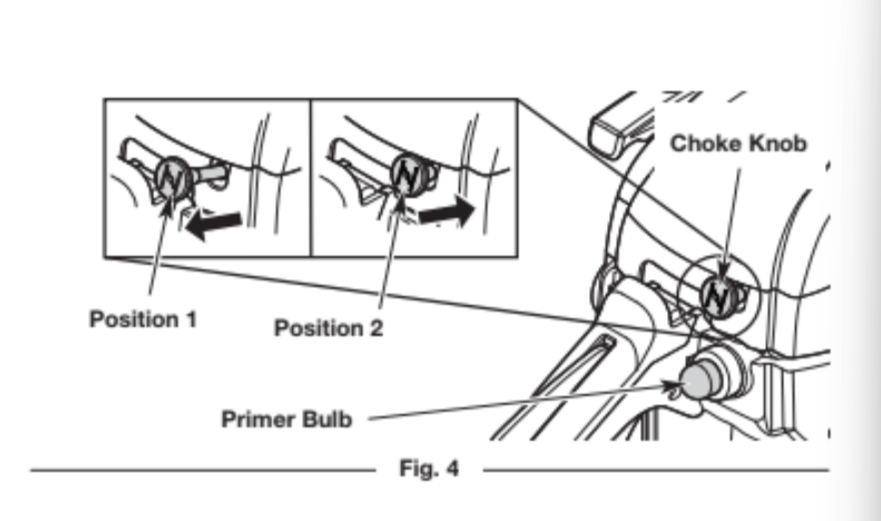
3. Pull the choke knob out to Position 1 (Fig. 4).
NOTE: DO NOT touch the throttle control (Fig. 3) until step 10.
4. Set the unit on a flat, level surface. Clear the area of any objects that could contact the saw chain.
5. Crouch in the starting position (Fig. 5). Hold the front handle with the left hand. Hold the starter rope grip with the right hand. Insert the right foot into the boot loop to help hold the unit firmly in place.
6. Pull the starter rope with a controlled and steady motion 5 times (Fig. 5).
7. Push the choke knob in to Position 2 (Fig. 4).
8. Pull the starter rope with a controlled and steady motion 3 to 5 times to start the engine.
9. Allow the engine to warm up for 30 to 60 seconds.
10. Press and hold the throttle lockout. Lightly squeeze and release the throttle control to idle the engine.
WARNING: The saw chain should not move when the engine runs at idle. If it does move, refer to Adjusting the
Idle Speed in the Maintenance section.
11. To reduce the chance of injury, engage the chain brake until you are ready to begin operation. When ready, disengage the chain brake. Then press the throttle lockout and squeeze the throttle control to accelerate the engine, as needed.
NOTE: The engine is properly warmed up when it accelerates without hesitation.
- IF... the engine hesitates, continue the warm-up.
- IF... the engine does not start, repeat the starting procedure.
- IF... the engine fails to start after a few attempts, move the choke knob to Position 2, press the throttle lockout and squeeze the throttle control. Pull the starter rope with a controlled and steady motion until the unit starts.
- IF... the engine is already warm, make sure the On/Off switch is in the On position, crouch in the starting position, pull the choke knob out to Position 1 and then push the choke knob back in to Position 2. Begin the starting procedure with step 8.
STOPPING INSTRUCTIONS
1. Release the throttle control and allow the engine to idle.
2. Move the On/Off switch to the Off (O) position (Fig. 3). Wait for the engine and saw chain to come to a complete stop.
Emergency Stopping
1. Push the chain brake lever forward to engage the chain brake. Refer to Testing the Chain Brake in the Assembly section.
2. Move the On/Off switch to the Off (O) position. Wait for the engine and saw chain to come to a complete stop.
OPERATION
WARNING: Always check the chain tension and adjust as necessary before beginning operation. Refer to Adjusting the Chain Tension in the Maintenance section.
WARNING: Make sure the chain oil reservoir is full before operation. Check the oil level constantly so that it
does not drop below half full. Make sure the chain oil adjustment screw is set appropriately. Refer to Setting the
Chain Oil Adjustment Screw in the Maintenance section. The saw chain must be continuously coated with oil to
function properly.
WARNING: Always wear appropriate eye, hearing, hand, foot and body protection to reduce the risk of injury when operating this unit. Wear head protection. Use a full face shield when needed. Refer to the Safety section for appropriate safety equipment information.
TIPS FOR BEST RESULT
• Follow all safety instructions. Refer to the Safety section.
• Only cut wood and materials made of wood. Do not attempt to cut sheet metal, plastics, masonry or any other non-wood materials.
• Practice cutting a few small logs before beginning a major cutting operation. First-time users should practice cutting logs on a sawhorse or cradle before undertaking other operations.
• Do not attempt to cut trees or logs with diameters larger than:
- 10 in. / 25.4 cm (S145 / CMXGSAMNN4214)
- 12 in. / 30.5 cm (S160 / CMXGSAMNN4216)
- 14 in. / 35.6 cm (S180 / CMXGSAMCX4218)
PREPARING THE WORK AREA
• Clear the area of children, bystanders and pets; keep them outside a 50-foot (15 m) radius, at a minimum. Even then, they are still at risk from thrown objects. Encourage bystanders to wear eye protection. If you are approached, stop the unit immediately. When felling, the safe distance is at least twice the height of the tallest tree in the work area. When bucking, keep workers at least 15 feet (4.6 m) apart.
• Keep the work area clean. Cluttered areas invite injuries. Do not start cutting until the work area is clear and free from obstructions. Make sure there is secure footing and a planned retreat path from falling trees or branches.
• Do not cut near electrical cables or power lines. Keep at least 50 feet (15 m) away from all power lines.
• Use the unit only in daylight or good artificial light.
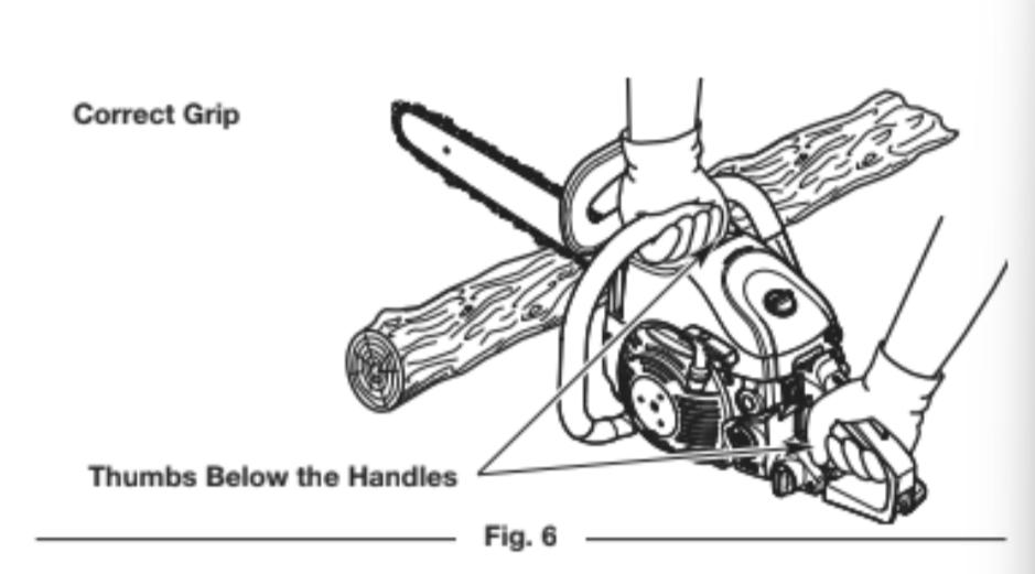
HOLDING THE UNIT
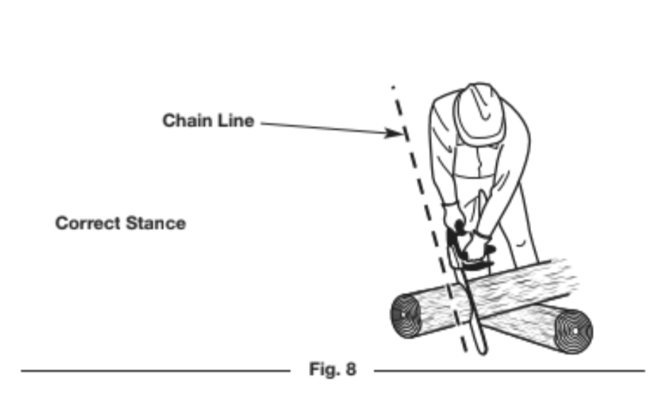
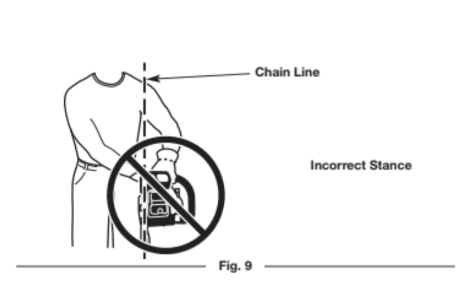
WARNING: Always use the hand placements specified below whether the operator is left-handed or right-handed. This will help keep the operator slightly to the left of the unit and out of the direct line of the saw chain if kickback occurs (Fig. 8 and Fig. 9). Always keep all body parts to the left of the chain line.
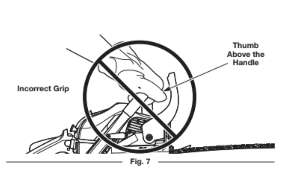
• Firmly encircle the handles with the thumbs and fingers (Fig. 6). This will help reduce the chance of losing control of the unit if kickback occurs. Any grip with thumbs and fingers on the same side of the handles is dangerous (Fig. 7).
• Always grip the unit firmly with both hands when the unit is running.
• Hold the front handle with the left hand. Keep the left arm straight to help withstand potential kickback.
• Hold the rear handle with the right hand. Keep the right arm slightly bent.
• Stand in a stable position with feet apart and firmly planted.
• Do not cut above shoulder height. Do not overreach.
CUTTING PROCEDURE BASICS
1. Start the unit. Refer to Starting Instructions in the Starting and Stopping section.
2. Keep your fingers off the throttle control until you are ready to make a cut.
3. Accelerate the unit to full speed before cutting.
4. Make sure that oil is flowing onto the guide bar and saw chain. A small spray should be visible. When using the unit for the first time, allow 30-60 seconds for the oil to begin flowing.
5. Press the unit against the wood and maintain a firm, steady pressure through most of the cut. Do not put pressure on the unit at the end of the cut.
6. Maintain a steady speed throughout the cut. Keep the unit running through the entire cut.
7. Do not try to force the saw through the wood. Allow the saw chain to do the cutting. Exert only light pressure. Forcing the cut could result in damage to the unit or personal injury.
8. Release the throttle control as soon as the cut is completed. Allow the saw chain to come to a complete stop. The saw chain, guide bar and engine may experience unnecessary wear if the
unit is run without a cutting load.
FELLING: SAFETY
Felling is the process of cutting down a tree. Follow these safety precautions to reduce the risk of serious injury, property damage and damage to electrical lines:
• Do not fell trees with an extreme lean. Do not fell trees with rotten limbs, loose bark or hollow trunks. Have these trees pushed or dragged down with heavy equipment.
• Do not cut trees near buildings or electrical lines. Leave these operations for professionals. If a felled tree does contact an electrical line, notify the utility company immediately.
• Check the tree for damaged or dead branches that could fall and cause serious injury.
• Remove dirt, stones, loose bark, nails, wire and other obstructions from the portion of the tree that will be cut.
• When bucking and felling operations are performed by two or more persons in the same general area, they should be separated from each other by a distance of at least twice the
height of the tree to be felled.
• Consider the force and direction of the wind. Consider the lean and balance of the tree. Consider the location of large branches. All of these factors influence the direction that the tree will fall. Do not try to fell a tree in a direction other than its natural fall line.
• Do not fell trees during periods of precipitation or high winds.
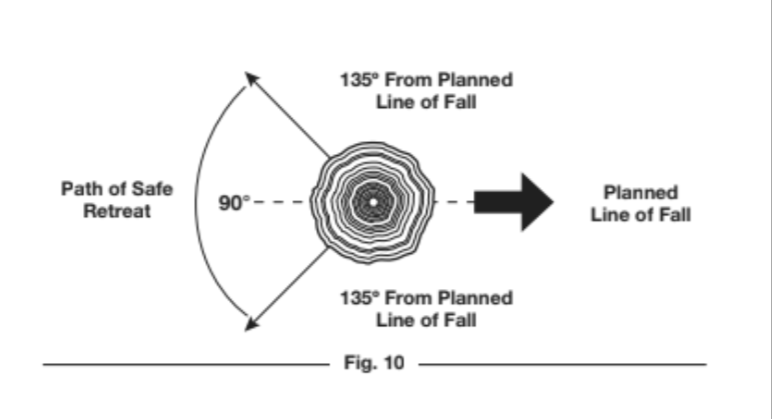
• Determine a safe and expedient escape route. Clear the area around the tree and make sure there are no obstructions blocking the escape route. Establish a 90o corridor of escape, approximately 135o from the line of fall (Fig. 10).
• Stay uphill from the tree; it will most likely roll or slide after it falls.
FELLING: PROCEDURE
Small trees, up to 6 - 7 inches (15 - 18 cm) in diameter, are usually felled in a single cut. Larger trees require a sequence of two cutting operations: a notched undercut followed by a felling back cut. It may also be necessary to remove buttress roots.
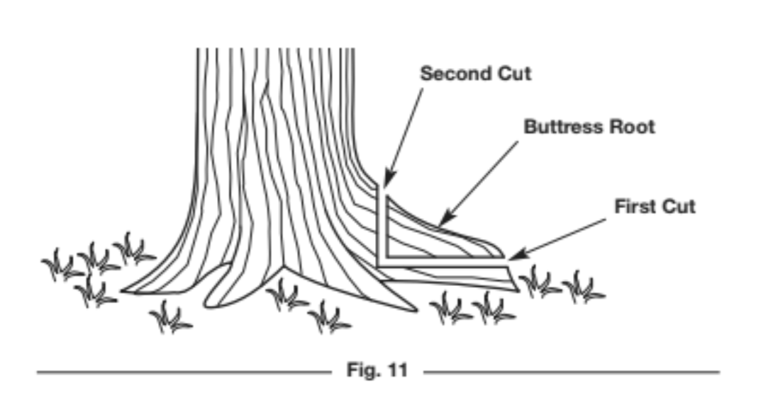
Step 1: Removing Buttress Roots
Buttress roots are large roots that extend above the ground and help support the tree. If the tree has large buttress roots that might impede the felling process, follow these steps to remove them:
1. Make a horizonal cut into the buttress root (Fig. 11). To prevent the guide bar from being pinched by the weight of the wood, always make this cut first.
2. Make a vertical cut into the buttress root (Fig. 11).
3. Remove the loose section from the work area.
Step 2: Making the Notched Undercut
WARNING: Never walk in front of a tree with a notched undercut.
This cut determines which direction the tree will fall. Always make this cut on the side of the tree facing the direction where the tree should fall. Make the cut at 90o to the line of fall.
1. Make a horizontal cut into the trunk of the tree (Fig. 12). The cut should be about 1/3 the diameter of the tree and close to the ground. To prevent the guide bar from being pinched by the weight of the wood, always make this cut first.
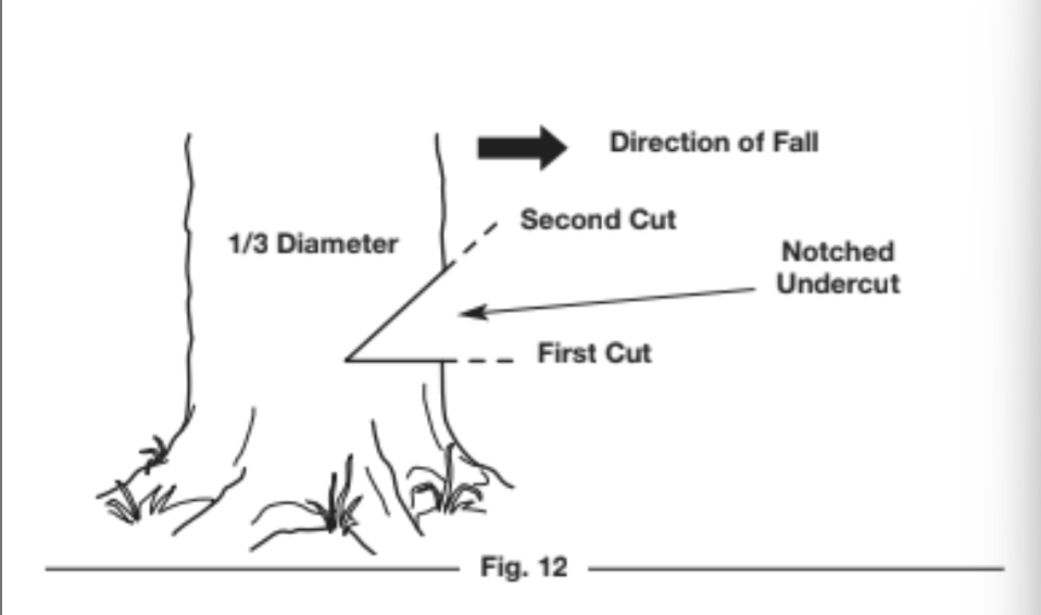
2. Make a 45o cut into the trunk of the tree, above the first cut (Fig.12). Continue cutting until the two cuts meet.
3. Remove the loose section from the work area.
Step 3: Making the Felling Back Cut
WARNING: Always recheck the area for bystanders, animals and obstacles before making the felling back cut.
This cut fells the tree.
1. Make a horizontal cut into the opposite side of the tree from the notched undercut (Fig. 13). Make the cut approximately 2 inches (5 cm) above the bottom of the notched undercut (Fig. 13).
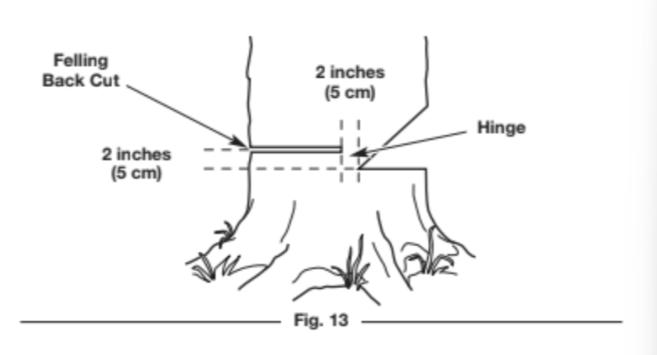
2. As the cut gets close to the notched undercut, only a thin band of wood will support the tree. This band of wood is referred to as the hinge (Fig. 13). The hinge helps control the fall of the tree. Leave approximately 2 inches (5 cm) of hinge in place. Do not cut through the hinge. Cutting through the hinge could cause the
tree to fall in any direction.
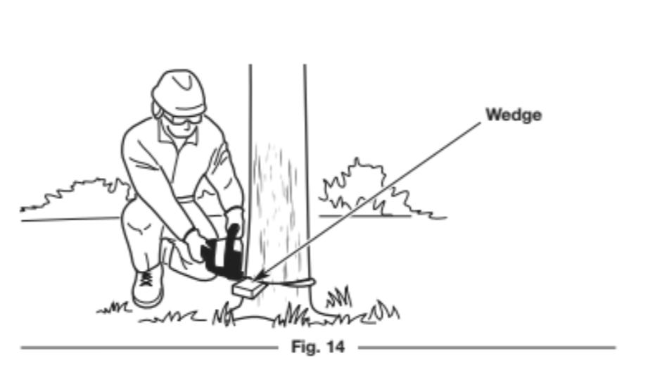
3. Periodically glance up during the felling back cut to see if the tree is going to fall in the correct direction. If there is a chance that the tree might not fall in the desired direction, or if the tree might rock back and bind the chain saw, remove the guide bar from the cut, stop the unit and use wedges to open the cut and
direct the fall (Fig. 14). Only use soft plastic or wooden wedges. Drive the wedges into the cut slowly. Once the wedges are in place and the cut is held open, either carefully reinsert the guide bar and continue the cut or slowly drive the wedges in further to push the tree over.
4. As the hinge gets smaller, the tree should begin to fall. When the tree begins to fall, remove the chain saw from the cut, stop the engine and set the unit down immediately. Promptly exit the area along the retreat path, but keep watching the tree as it falls.
DANGER: If the tree starts to fall in the wrong direction and binds the chain saw, leave the unit and evacuate the area immediately! Do not try to save the chain saw!
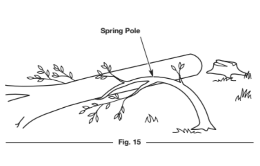
WARNING: Stay clear of spring poles when operating the unit. Spring poles are branches, logs, roots or saplings that are bent under tension by other wood (Fig. 15). When the tension is released, spring poles can strike the operator, causing serious injury and potentially knocking the chain saw into the operator’s body. Use extreme caution when cutting spring poles or when releasing the cause of tension.
LIMBING
Limbing is the process of removing branches from a fallen tree.
1. Leave the larger support limbs under the tree for last (Fig. 16).These will keep the tree off the ground during the limbing process.
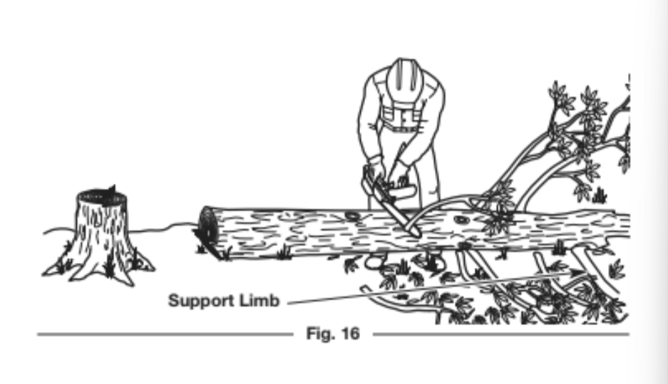
2. Cut one limb at a time. Stand on the opposite side of the tree from the limb (Fig. 16). Keep the trunk between the operator and the chain saw. To avoid binding the chain saw, branches under tension should be cut from the bottom up.
3. Remove the cut limbs from the work area.
BUCKING: SAFETY
Bucking is the process of cutting a fallen tree into logs of desired lengths. Follow these safety precautions to reduce the risk of serious injury:
• Clear the area of objects or obstructions that could contact the guide bar and result in kickback.
• When bucking on a slope, always stand on the uphill side of the fallen tree.
• If possible, the end of the tree to be cut should be raised off of the ground. A saw horse is ideal for this purpose. If a saw horse is not available, use other logs or any remaining limb stumps. Make sure the tree if firmly supported.
• Do not let the saw chain contact the ground or saw horse.
• Cut one log at a time. Release the throttle control and allow the saw chain to come to a complete stop before moving on to the next log.
• Keep feet and all other body parts clear of falling logs.
DANGER: Use extreme caution when cutting a fallen tree that is still attached to the root structure. When the
trunk is separated from the roots, the stump has a high potential for rocking back into the hole created by the
roots. This can result in serious injury or death. Never stand in the hole left by the roots. Never allow others to
stand near the root structure.
BUCKING: PROCEDURE
Cutting Logs Under Stress
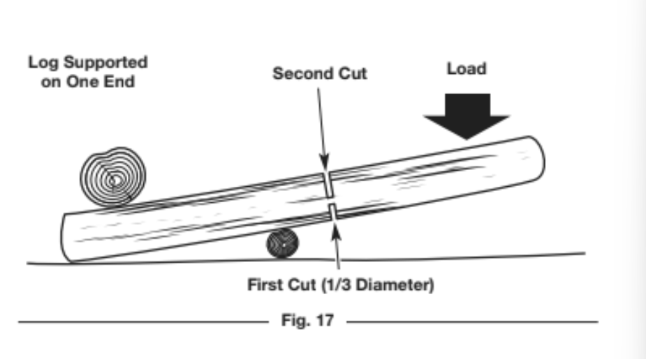
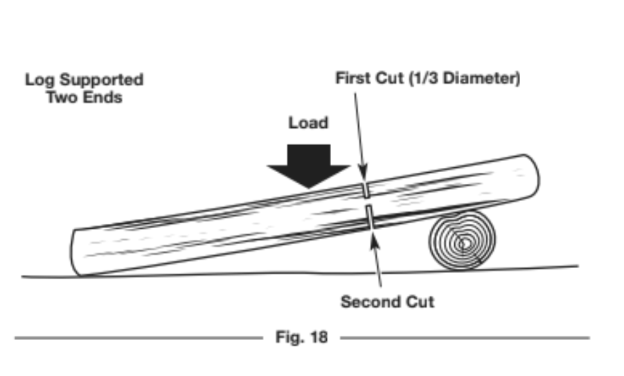
When logs are supported on one or both ends, the wood tends to bend during the cutting process. This can cause the chain saw to become pinched between the two sides. Pay extra attention.
1. Make the first cut approximately 1/3 the diameter of the log. Do not cut deeper than 1/3.
• If the log is supported on one end (Fig. 17), make the first cut from below (underbucking). Refer to Underbucking.
• If the log is supported on two ends (Fig. 18), make the first cut from above (overbucking). Refer to Overbucking.
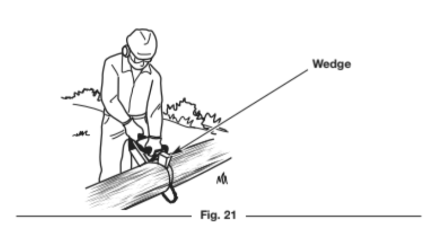
2. Make the second cut from the opposite side until the two cuts meet. If the diameter of the wood is large enough, insert soft plastic or wooden wedges to hold the cut open and prevent pinching (Fig. 21). Take care not to touch the wedges with the saw chain.
Cutting Fully-Supported Logs
When logs are supported along the entire length, extra care should be taken to make sure the saw chain does not contact the ground or other support structure (Fig. 19).
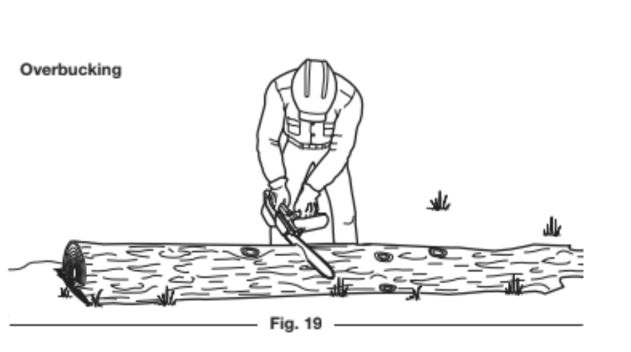
1. Cut through the log as much as possible, without cutting into the ground or support structure. Cut from above (overbucking). Refer to Overbucking.
2. Roll the log over and finish cutting through the log from above (overbucking).
Overbucking
1. Begin cutting from above, with the bottom of the saw chain against the top of the log (Fig. 19).
2. Exert light, downward pressure. The saw will tend to pull away from the operator. Be prepared and hold the saw firmly to maintain control.
Underbucking
1. Begin cutting from below, with the top of the saw chain against the bottom of the log (Fig. 20).
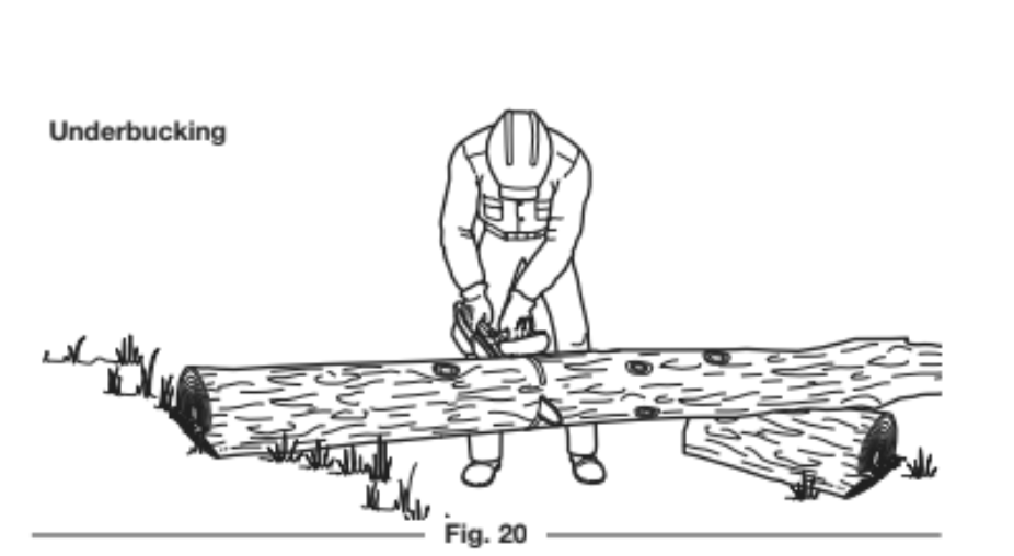
2. Exert light, upward pressure. The saw will tend to push toward theoperator. Be prepared and hold the saw firmly to maintain control.
WARNING: Do not cut above shoulder height with a chain saw. Use a pole saw to cut limbs above shoulder
height or hire a professional. Do not operate the unit in a tree or on a ladder unless specifically trained to do so.
WARNING: Falling branches can cause serious injury. Always wear appropriate head protection. Plan an escape route away from falling limbs. Do not position any body parts directly below the limb when cutting.
Pruning is the process of cutting limbs from a living tree.
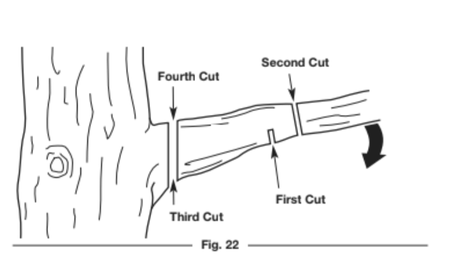
1. Make the first cut approximately 6 inches (15 cm) from the tree trunk. Cut upward, from the underside of the limb. Use the top of the guide bar to make this cut. Cut a third of the way through the diameter of the limb (Fig. 22).
2. Make the second cut 2 - 4 inches (5 - 10 cm) farther out on the limb. Cut downward, from the top of the limb. Use the bottom of the guide bar to make this cut. Cut completely through the limb (Fig. 22).
3. Make the third cut as close to the tree trunk as possible. Cut upward, from the underside of the limb stub. Use the top of the guide bar to make this cut. Cut a third of the way through the diameter of the limb (Fig. 22).
4. Make the fourth cut directly above the third cut. Cut downward, from the top of the limb stub. Use the bottom of the guide bar to make this cut. Cut completely through the limb stub to meet the third cut (Fig. 22). This will remove the limb stub.
MAINTENANCE
WARNING: To avoid serious personal injury, always stop the engine and allow it to cool before cleaning or maintaining the unit. Never perform cleaning or maintenance while the unit is running. Disconnect the spark plug wire to prevent the unit from starting accidentally.
WARNING: Wear protective clothing and observe al safety instructions to prevent serious personal injury.
MAINTENANCE SCHEDULE
Perform these required maintenance procedures at the frequency stated in the table. These procedures should also be a part of any seasonal tune-up.
All service, other than the maintenance procedures described in this manual, should be performed by an authorized service dealer.
NOTE: Some maintenance procedures may require special tools or skills. If you are unsure about these procedures, take the unit to an authorized service dealer. Call 1-888-331-4569 for more information.
NOTE: Maintenance, replacement, or repair of the emission control devices and system may be performed by an authorized service dealer. Call 1-888-331-4569 for more information.
NOTE: Please read the California/EPA statement that came with the unit for a complete listing of terms and coverage for the emissions control devices, such as the spark arrestor, muffler, carburetor, etc.
CUSTOMER RESPONSIBILITY
Before each use:
• Check for loose screws, nuts or bolts (tighten as needed)
• Check for damaged or worn parts*
• Check the saw chain sharpness. Refer to Sharpening the Saw Chain.
• Test the chain brake*. Refer to Testing the Chain Brake.
• Check the chain tension (adjust as needed). Refer to Adjusting the Chain Tension.
• Fill the chain oil reservoir (refill frequently). Refer to Adding Bar and Chain Oil.
• Fill the fuel tank with fresh, properly mixed fuel. Refer to the Oil and Fuel section.
• Clean the air filter. Refer to Maintaining the Air Filter.
After each use:
• Clean the unit and inspect decals. Refer to Cleaning in the Cleaning and Storage section.
Every 10 hours:
• Check the spark plug condition and gap. Refer to Maintaining the Spark Plug.
• Clean the guide bar groove and oil passages. Lubricate the sprocket tip. Refer to Maintaining the Guide Bar.
• Clean the cylinder fins. Refer to Cleaning in the Cleaning and Storage section.
* If maintenance or replacement is required, have the unit serviced by an authorized service dealer.
ADDING BAR AND CHAIN OIL
DANGER: Failure to fill the chain oil reservoir will cause irreparable damage to the unit. Make sure the chain oil
reservoir is always filled. Always use bar and chain oil.
WARNING: Oil constantly flows from the chain oil reservoir to oil the saw chain. Check the chain oil level
frequently so that it does not drop below half full.
The guide bar and saw chain require lubrication to minimize friction. Never starve the guide bar and chain of lubricating oil. Running the unit without enough oil will decrease cutting efficiency, shorten the life of the saw chain, cause rapid dulling of the saw chain and excessive wear to the guide bar from overheating. An insufficient amount of lubricating oil is evidenced by smoke, guide bar discoloration or pitch build-up.
Only use bar and chain oil that is formulated to perform over a wide range of temperatures with no diluting required in the chain oil reservoir. Do not use motor oil or any other petroleum-based oil. Do not use dirty, used or contaminated oil. Damage may occur to the guide bar or saw chain. Dispose of old oil according to federal, state and local regulations.
1. Set the unit on a flat, level surface.
2. To prevent debris from entering the chain oil reservoir, use a damp cloth to clean the chain oil cap and surrounding area.
3. Unscrew the chain oil cap (Fig. 23).
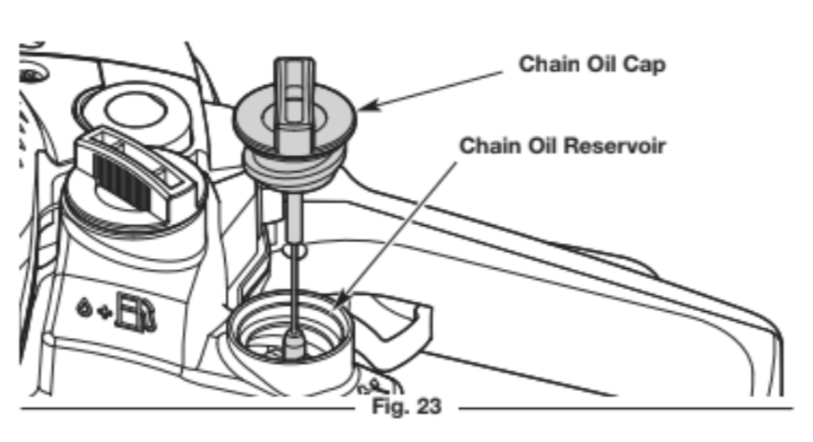
4. Carefully pour the oil into the chain oil reservoir. DO NOT overfill.
5. Reinstall the chain oil cap. Tighten the cap firmly.
6. Wipe up any oil that may have spilled.
ADJUSTING THE BAR AND CHAIN OIL FLOW
Bar and chain oil will slowly flow from the chain oil reservoir onto the chain. Approximately one tank of bar and chain oil is used for every tank of fuel.
1. To increase the oil flow, turn the automatic oiler adjustment screw counterclockwise with a flat-head screwdriver (Fig. 24).
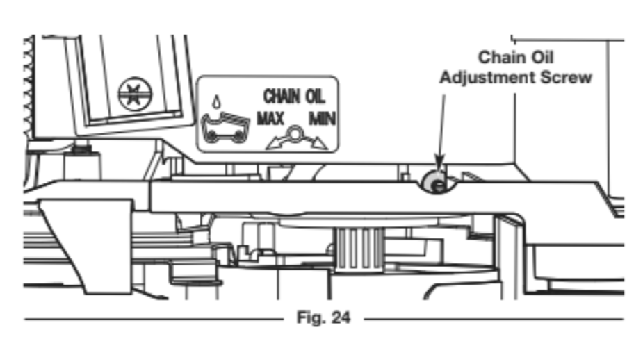
2. To decrease the oil flow, turn the automatic oiler adjustment screw clockwise with a flat-head screwdriver (Fig. 24).
ADJUSTING THE CHAIN TENSION
CAUTION: The guide bar, saw chain, and saw bearings will wear more rapidly if the saw chain is not properly
tensioned. Maintaining proper chain tension will improve cutting performance and prolong the life of the saw chain.
WARNING: To prevent serious injury, never touch the saw chain or adjust the chain tension while the unit is
running. Disconnect the spark plug wire to prevent the unit from starting accidentally.
WARNING: The saw chain is very sharp. Always wear heavy-duty protective gloves when handling or performing maintenance on the saw chain.
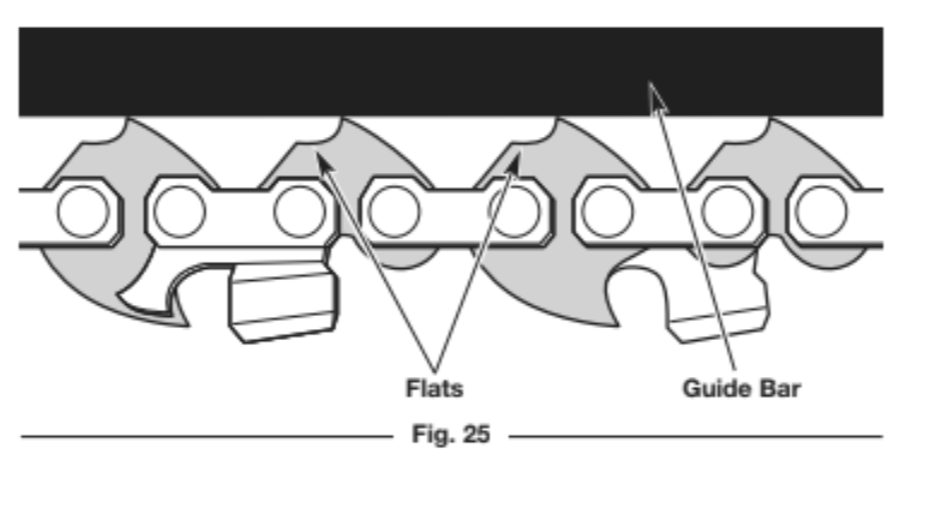
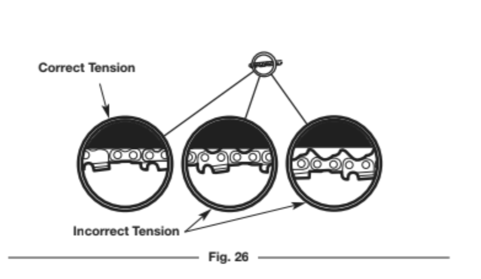
Check the chain tension before and during operation. The saw chain will expand as it heats up during operation. Adjust the chain tension whenever the flats on the saw chain hang out of the bar groove (Fig.25 and Fig. 26).
NOTE: A new saw chain tends to stretch and will need readjustment after as few as five (5) cuts. This is normal during the break-in period. The interval between future adjustments will lengthen quickly.
1. Make sure the chain brake is disengaged. Refer to Testing the Chain Brake in the Assembly section.
2. Use the multi-purpose tool or a 1/2 inch (13 mm) wrench to slightly loosen the bar-retaining nuts (Fig. 27). DO NOT remove the bar cover.
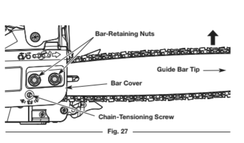
3. Hold the guide bar tip up and use a flat-head screwdriver to turn the chain-tensioning screw (Fig. 27).
• Turn the chain-tensioning screw clockwise to tighten the saw chain.
• Turn the chain-tensioning screw counterclockwise to loosen the saw chain.
The saw chain should fit snuggly against the underside of the guide bar. There should be no sag (Fig. 26).
4. Continue to hold the guide bar tip up and move the saw chain back and forth along the guide bar (Fig. 28). Make sure the saw chain moves freely and is in proper mesh with the sprocket. If the saw chain does not move easily, slowly turn the chain-tensioning screw counterclockwise to loosen the saw chain.
NOTE: The saw chain will not move if the chain brake is engaged.
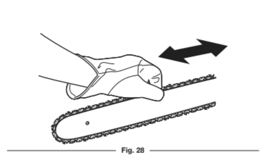
5. Continue to hold the guide bar tip up and securely tighten the bar-retaining nuts.
CAUTION: If the saw chain was tensioned while warm, it may become too tight when cooled. Loosen the chain
tension after operation and check the chain tension before the next use.
REMOVING AND INSTALLING THE GUIDE BAR AND SAW CHAIN
WARNING: The saw chain is very sharp. Always wear heavy-duty protective gloves when handling or performing maintenance on the saw chain.
The guide bar and saw chain need to be removed when certain maintenance procedures are performed, such as when rotating the guide bar. When replacing old guide bars and saw chains with new parts, always use the manufacturer’s specified replacement parts. Refer to Replacing the Guide Bar and Saw Chain.
Removing the Guide Bar and Saw Chain
1. Make sure the chain brake is disengaged. Refer to Testing the Chain Brake in the Assembly section.
2. Use the multi-purpose tool or a 1/2 inch (13 mm) wrench to loosen the bar-retaining nuts (Fig. 29).
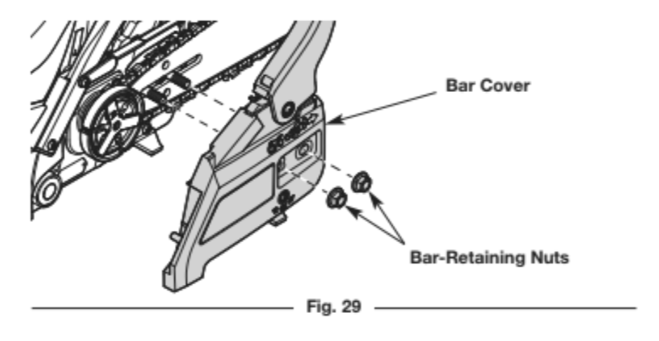
3. Remove the bar-retaining nuts and bar cover (Fig. 29).
4. Loosen the saw chain. Refer to Adjusting the Chain Tension.
5. Remove the guide bar and saw chain from the guide bar bolts (Fig. 31).
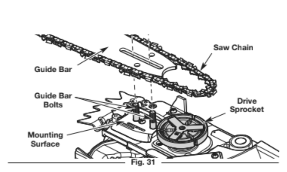
6. Remove the saw chain from the guide bar. Installing the Guide Bar and Saw Chain
1. Set the saw chain on a clean, flat surface and straighten out any kinks.
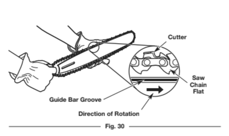
2. Fit the saw chain into the guide bar groove (Fig. 30). Make sure the cutters point in the correct direction of rotation (Fig. 30). Keep a loop of saw chain at the back end of the guide bar (Fig. 30).
3. Hold the saw chain and guide bar together in position over the unit. Loop the saw chain around the drive sprocket and install the guide bar onto the guide bar bolts (Fig. 31). Make sure the guide bar is flush against the mounting surface. Make sure the flats on the saw chain are in the grooves on the drive sprocket.
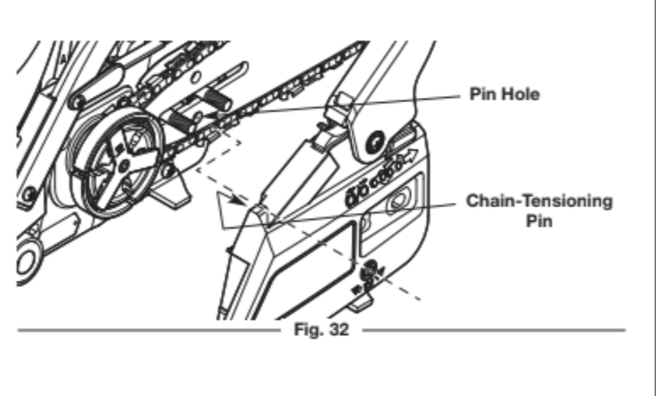
4. Install the bar cover. Make sure the chain-tensioning pin is in the pin hole on the guide bar (Fig. 32).
5. Place the bar-retaining nuts onto the guide bar bolts and tighten them hand tight. DO NOT tighten the bar-retaining nuts completely.
6. Make sure the saw chain is still in the guide bar groove. Adjust the chain tension. Refer to Adjusting the Chain Tension.
7. Hold the guide bar tip up and securely tighten the bar-retaining nuts.
MAINTAINING THE SAW CHAIN
For safe, efficient operation, the saw chain must be maintained properly.
The saw chain will wear with use, causing the chain to stretch. This is normal. When it is no longer possible to obtain a correct chain-tension adjustment, the saw chain will need to be repaired by an authorized service dealer or replaced. Refer to Replacing the Guide Bar and Saw Chain.
Always keep the saw chain sharp. During operation, look for the following indicators of a dull saw chain:
• Wood chips are small and powdery.
• The saw chain must be forced through the wood.
• The saw chain cuts to one side.
If any of these conditions exist, sharpen or replace the saw chain. Refer to Sharpening the Saw Chain or Replacing the Guide Bar and Saw Chain.
NOTE: If you do not fully understand the process for properly sharpening a saw chain after reading the instructions, have the saw chain sharpened by an authorized service center or replace the saw chain.
SHARPENING THE SAW CHAIN
WARNING: The saw chain is very sharp. Always wear heavy-duty protective gloves when handling or performing maintenance on the saw chain.
WARNING: An improperly sharpened saw chain increases the chance of kickback. Failure to replace or
properly maintain the saw chain can cause serious injury.
CAUTION: A dull or improperly sharpened saw chain can cause excessive engine speed during operation, which can result in severe engine damage.
If the saw chain was damaged by contacting hard objects, such as nails or stones, or was abraded by mud or sand on the wood, have an authorized service dealer sharpen the saw chain.
When sharpening the saw chain, file all cutters to the specified angles and measurements. Other angles or measurements can cause excessive wear to the guide bar and saw chain, cause the chain to dull quickly and increase the chance of kickback. Fast cutting can be obtained only when all cutters are uniform.
1. Tighten the chain tension so that the saw chain is taut and does not wobble. Refer to Adjusting the Chain Tension.
• Always file the saw chain at the midpoint of the guide bar.
2. Use a round file and file holder (tools not included) to sharpen the top plate and side plate of each cutter.
• Use a 5/32 inch (4 mm) diameter file.
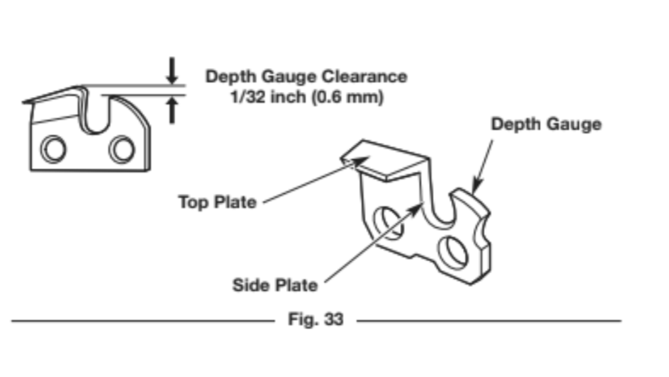
• Keep the file level with the top plate of the cutter (Fig. 33). Do not let the file dip or rock. Use light, but firm pressure.
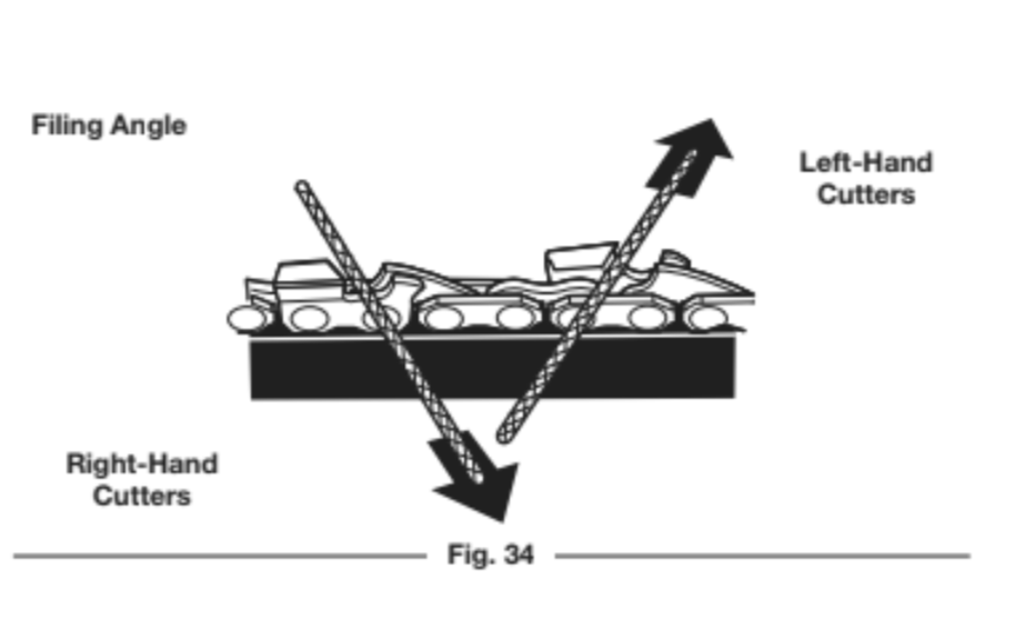
• File toward the front corner of the cutter (Fig. 34). Lift the file away from the cutter at the end of the forward stroke. Only file on the forward stroke.
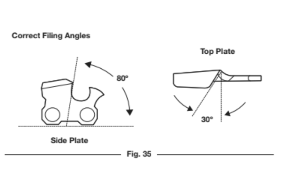
• Apply a few firm strokes to each tooth. When filed correctly, the top plate will be at a 30o angle and the side plate will be at an 80o angle (Fig. 35). Using the correct file and file holder will automatically produce the correct angles.
• File all the left-hand cutters in one direction (Fig. 34). Then move to the other side of the saw chain and file all of the right-hand cutters in the opposite direction (Fig. 34).
• Occasionally remove filings with a wire brush.
3. Use a depth gauge tool (not included) to measure the depth gauge clearance (Fig. 36) of each cutter. The depth gauge clearance must be maintained at 1/32 inch (0.6 mm). The depth gauge clearance determines the depth at which the cutter enters the wood during operation and the size of the wood chips produced. Too much clearance increases the chance of kickback. Too little clearance decreases the size of the woodchips, thus deceasing the ability to cut.
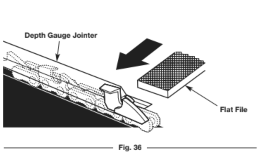
• Use a 1/32 inch (0.6 mm) depth gauge jointer and a flat file (tools not included) to lower the depth gauge to the correct clearance (Fig. 36).
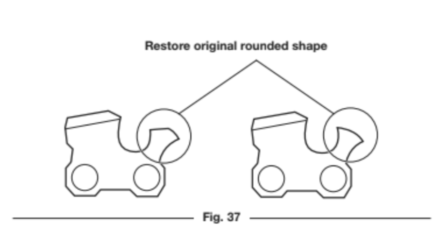
• After lowering the depth gauge, use the flat file to restore the original rounded shape to the depth gauge (Fig. 37). Take care not to damage the cutting edges or nearby links.
MAINTAINING THE GUIDE BAR
1. Rotate the guide bar frequently, at regular intervals (for example, after every 5 hours of operation), to ensure even wear on the top and bottom of the guide bar. Refer to Removing and Installing the Guide Bar and Saw Chain.
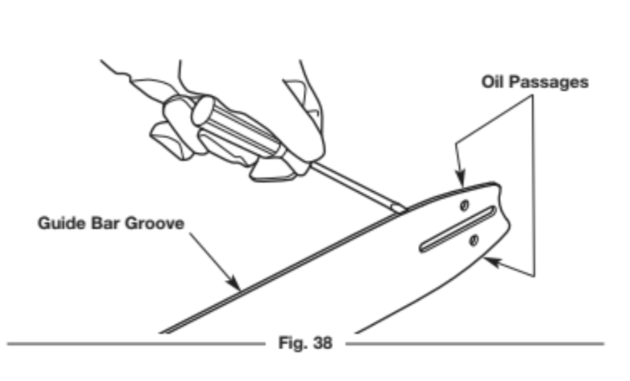
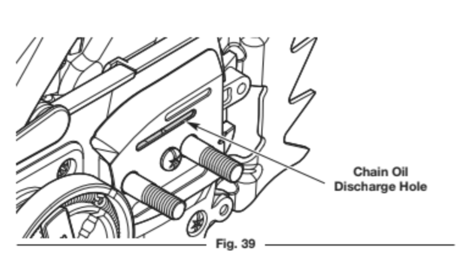
2. Clean the guide bar groove and oil passages whenever the saw chain is removed, when the unit has been used heavily or when the saw chain appears dirty. Use a screwdriver, putty knife, wire brush or similar instrument to remove debris from the guide bar groove (Fig. 38). Use a small, soft wire to remove any debris from the chain oil discharge hole (Fig. 39).
NOTE: If the oil passages are clear, the saw chain will give off a spray of oil shortly after it begins to rotate during operation.
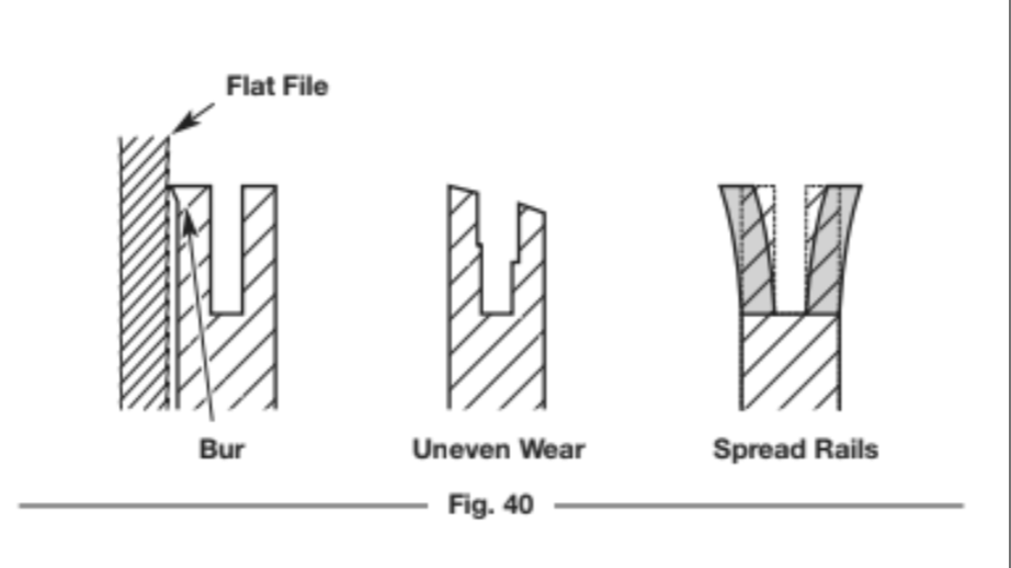
3. Frequently check the guide bar for damage (Fig. 40). Feathering and burring of the guide bar rails (the ridges on either side of the bar groove) is a normal process of guide bar wear. Such faults should be smoothed with a file as soon as they occur (Fig. 40). A guide bar with the following faults should be replaced:
• Wear inside the guide bar rails that permits the chain to lay
sideways
• Bent guide bar
• Cracked or broken rails
• Spread rails
Refer to Replacing the Guide Bar and Saw Chain.
Lubricating the Guide Bar Sprocket Tip
The guide bar sprocket tip was lubricated at the factory, but requires regular lubrication. Failure to lubricate the guide bar sprocket tip will result in poor performance, damage to the unit and will VOID the warranty.
NOTE: This procedure can be performed while the guide bar and saw chain are still assembled on the unit.
1. Clean the guide bar sprocket tip thoroughly with a damp cloth
(Fig. 41).
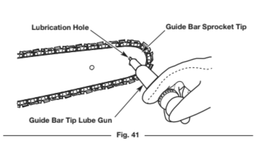
2. Use a guide bar tip lube gun (not included) to inject grease into the lubrication hole (Fig. 41). Inject grease until it appears on the outer edge of the guide bar sprocket tip.
3. Rotate the saw chain by hand. Always wear heavy-duty protective gloves. Make sure the chain brake is disengaged.
4. Repeat the lubrication process until the entire guide bar sprocket tip is lubricated.
REPLACING THE GUIDE BAR AND SAW CHAIN
WARNING: Always use a low-kickback saw chain, which significantly reduces the danger of kickback. Low-
kickback saw chain does not completely eliminate kickback. A low-kickback or “safety chain,” should never
be regarded as total protection against injury.
When replacing the guide bar and saw chain, only use the replacement parts specified by the manufacturer or their equivalents. Refer to Replacement Parts. Use of any unauthorized parts or accessories could lead to serious injury to the operator or damage to the unit and will VOID the warranty.
Always use a replacement saw chain designated as “low-kickback” or a saw chain that meets the low-kickback performance requirements. A standard saw chain (a chain that does not have the kickback-reducing guard links) should only be used by an experienced professional chain saw operator.
MAINTAINING THE AIR FILTER
WARNING: To avoid serious personal injury, always stop the engine and allow it to cool before cleaning or maintaining the unit.
Failure to maintain the air filter can result in poor performance or can cause permanent damage to the engine. Engine failure due to improper air filter maintenance is not covered by the product warranty.
Cleaning the Air Filter
1. Turn the knob on the air filter cover counterclockwise to loosen the air filter cover (Fig. 42).
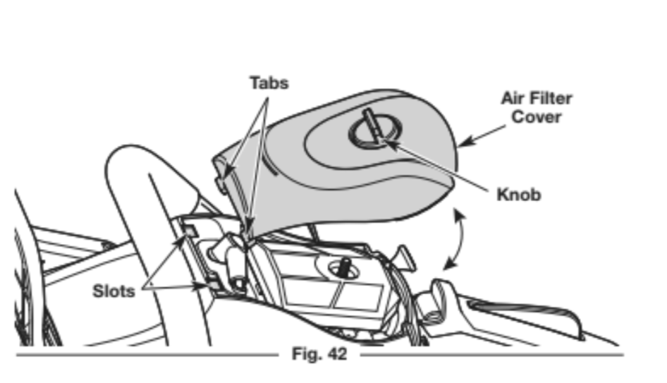
2. Remove the air filter cover (Fig. 42).
3. Remove the air filter (Fig. 43).
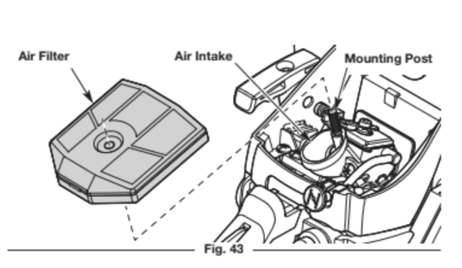
4. Wash the air filter in mild detergent and water. Rinse the air filter thoroughly and allow it to dry.
5. Reinstall the air filter onto the mounting post (Fig. 43). Make sure the opening in the air filter sits securely in the air intake (Fig. 43).
NOTE: Operating the unit without the air filter and air filter cover will VOID the warranty. Keep a supply of spare air filters.
6. Place the air filter cover back onto the unit. Insert the two tabs on the air filter cover into the two slots on the chain saw housing (Fig. 42).
7. Turn the knob clockwise to tighten the air filter cover securely.
ADJUSTING THE IDLE SPEED
WARNING: The saw chain may spin during idle speed adjustments. Wear protective clothing and observe all
safety instructions to prevent serious personal injury.
If the engine will not idle properly:
1. Start the engine. Refer to Starting and Stopping.
2. Release the throttle control and let the engine idle.
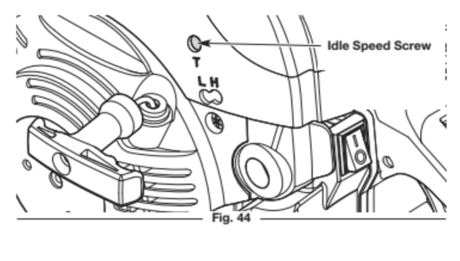
• If the engine stops, increase the idle speed. Use a small Phillips screwdriver to turn the idle speed screw clockwise, 1/8 of a turn at a time, until the engine idles smoothly (Fig. 44).
• If the saw chain spins when the engine idles, reduce the idle speed. Turn the idle speed screw counterclockwise, 1/8 of a turn at a time, until the saw chain stops moving (Fig. 44).
MAINTAINING THE SPARK PLUG
1. Stop the engine and allow it to cool.
2. Turn the knob on the air filter cover counterclockwise to loosen the air filter cover (Fig. 42).
3. Remove the air filter cover (Fig. 42).
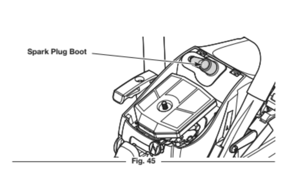
4. Grasp the spark plug boot firmly and pull it from the spark plug (Fig. 45).
5. Clean around the spark plug. Remove the spark plug from the
cylinder head with the multi-purpose tool or a 5/8-inch socket
wrench, turning counterclockwise.
WARNING: Do not sand blast, scrape or clean spark plug electrodes. Grit in the engine could damage the cylinder.
6. Inspect the spark plug. If the spark plug is cracked, fouled or dirty, replace it with replacement part #794-00204, a Champion RZ7C or an equivalent spark plug.
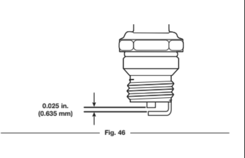
7. Use a feeler gauge to set the air gap at 0.025 in. (0.635 mm) (Fig. 46).
8. Install the spark plug in the cylinder head. Tighten the spark plug with the multi-purpose tool or a 5/8-inch socket wrench, turning it clockwise until snug.
NOTE: If using a torque wrench, torque to: 110-120 in.•lb. (12.3-13.5 N•m). Do not over tighten.
9. Reattach the spark plug boot.
10. Place the air filter cover back onto the unit. Insert the two tabs on the air filter cover into the two slots on the chain saw housing (Fig. 42).
CLEANING AND STORAGE
CLEANING
WARNING: To avoid serious personal injury, always stop the engine and allow it to cool before cleaning or maintaining the unit.
1. Loosen the saw chain if the chain tension was adjusted during operation. The saw chain will contract as the unit cools, which could damage the unit if the chain is too tight.
2. Clean the unit with a damp cloth. Do not douse the unit with water. Do not use strong detergents. Household cleaners that contain aromatic oils such as pine and lemon, and solvents such as kerosene, can damage plastic.
NOTE: When preparing the unit for long-term storage (30 days or more), remove the guide bar and saw chain. Carefully clean the guide bar cover, guide bar mounting surface and sprocket. Use a firm non-wire brush to clean the guide bar groove.
Reassemble the unit.
3. Wipe off any moisture with a soft cloth.
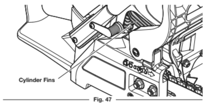
4. Use compressed air, up to 40 PSI, to blow debris from the cylinder fins (Fig. 47). The cylinder fins must be cleaned on a regular basis to reduce the risk of personal injury or damage to the unit as a result of fire. Always use safety goggles/glasses when using compressed air. Do not use water or other liquids to clean the cylinder fins. Use a small wire brush to remove stubborn debris. If a significant amount of debris remains, have the unit cleaned by an authorized service dealer.
5. Lightly coat the guide bar and saw chain with a corrosion- inhibiting oil.
STORAGE
• Loosen the saw chain if the chain tension was adjusted during operation. The saw chain will contract as the unit cools, which could damage the unit if the chain is too tight.
• Allow the engine to cool before storing.
• Thoroughly clean the unit and inspect it for any loose or damaged parts. Repair or replace damaged parts and tighten loose screws, nuts or bolts.
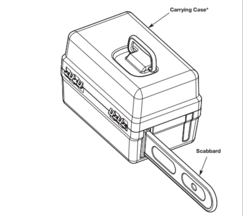
• Cover the guide bar and saw chain with the scabbard.
• Never store a fueled unit where fumes may reach an open flame or spark.
• Lock up the unit to prevent unauthorized use or damage.
• Store the unit in a dry, well-ventilated area.
• Store the unit out of the reach of children.
NOTE: It is normal for bar and chain oil to seep from the unit when not in use. Please take this into consideration when storing the unit.
Long-term Storage (30 days or more)
1. Remove the fuel cap, tip the unit and drain the fuel into an approved container. Reinstall the fuel cap.
2. Start the engine and allow it to run until it stalls. This ensures that all fuel has been drained from the carburetor.
3. Allow the engine to cool. Remove the spark plug and put 5 drops of any high-quality motor oil or 2-cycle oil into the cylinder. Pull the starter rope slowly to distribute the oil. Reinstall the spark plug.
Preparing the Unit for Use after Long-term Storage
1. Remove the spark plug. Tip the unit and drain all of the oil from the cylinder into an approved container. Reinstall the spark plug.
NOTE: Do not use fuel that has been stored for more than 30 days. Dispose of old fuel and oil according to federal, state and local regulations.
TROUBLESHOOTING
THE ENGINE WILL NOT START
- The fuel tank is emty
- Fill the fuel tank with properly-mixed fuel
- The primer bulb was not pressed enough
- Press the primer bulb 10 times or until fuel is visible
- The engine is flooded
- Move the choke knob to Position 2, press the throttle lockout,
- The fuel is old (over 30 days) and/or improperly mixed
- Drain the fuel tank and add fresh, properly-mixed fuel
- The spark plug is not working properly
- Refer to Maintaining the Spark Plug
THE ENGINE WILL NOT IDLE
- The air filter is dirty
- Clean or replace the air filter
- The air filter is dirty
- Drain the fuel tank and add fresh, properly-mixed fuel
- The idle speed is incorrect
THE ENGINE WILL NOT ACCELERATE
- The fuel is old (over 30 days) and/or improperly mixed
- Drain the fuel tank and add fresh, properly-mixed fuel
- The air filter is dirty
- Clean or replace the air filter
THE ENGINE LACKS POWER OR STALLS
- The fuel is old (over 30 days) and/or improperly mixed
- Drain the fuel tank and add fresh, properly-mixed fuel
- The air filter is dirty
- Clean or replace the air filter
- The spark plug is not working properly
- Refer to Maintaining the Spark Plug
THE SAW CHAIN COMES OFF THE GUIDE BAR
- The saw chain tension is too loose
- Adjust the saw chain tension
- The guide bar and saw chain are assembled incorrectly
- Refer to Removing and Installing the Guide Bar and Saw Chain
THE GUIDE BAR AND SAW CHAIN ARE RUNNING HOT, SMOKING OR STUCK
- The saw chain tension is too tight
- Adjust the saw chain tension
- The chain oil reservoir is empty
- Refill the chain oil reservoir
- The guide bar groove and oil passages are dirty
- Clean the guide bar and oil passages
- The automatic oiler flow is too low
THE SAW CHAIN DOES NOT ROTATE
- The saw chain tension is too tight
- Adjust the saw chain tension
- The guide bar and saw chain are assembled incorrectly
- Refer to Removing and Installing the Guide Bar and Saw Chain
- The guide bar and saw chain are damaged
- Inspect the guide bar and saw chain for damage. Replace them if
- The drive assembly is damaged
- Refer to Service information
- The chain brake is engaged
- Disengage the chain brake
THE SAW CHAIN ROTATES, BUT DOES NOT CUT
- The saw chain is dull
- Sharpen or replace the saw chain
- The saw chain is on backwards
- Check and correct the saw chain direction


