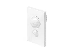
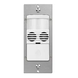
The Lutron® Maestro® Occupancy sensing switch combines a Maestro® switch with a passive infrared occupancy or vacancy sensor. The sensor detects the heat from occupants moving within an area to determine whether the space is occupied. Based on the feedback from the sensor, the occupancy sensing switch will adjust the load accordingly.
Features
Passive infrared sensors with exclusive Lutron® XCTTM Technology for fine motion detection
180° sensor field-of-view
Up to 30 ft x 30 ft (9 m x 9 m) [900 ft2 (81 m2)] major motion coverage and 20 ft x 20 ft (6 m x 6 m) [400 ft2 (36 m2)] minor motion coverage
Occupancy version can be set to Auto-ON / Auto-OFF or Manual-ON / Auto-OFF
Vacancy version available to meet CA Title 24 requirements
Adjustable timeout (1,5, 15, or 30 minutes) and high/low sensitivity adjustment
Occupancy sensing switch loads: incandescent, halogen, ELV, MLV, CFL, LED, magnetic fluorescent, electronic fluorescent, and fan.
Advanced Features
Switching
Standard zero cross—maximizes relay life by switching at the point of minimum energy on the AC power curve.
Adaptive zero cross—maximizes relay life by switching at the point of minimum energy on the AC power curve. Actively adapts to variations in relay timing.
Lutron® Patented Softswitch® circuit—eliminates arcing at mechanical contacts when loads are switched. Extends relay life to an average of 1,000,000 cycles (on/off) for resistive, capacitive, or inductive sources.
XCT TM Technology
Advanced sensing technology for fine motion detection ensures that the lights stay on while the room is occupied, and that the sensor does not turn on falsely when there is no occupancy in the room.
Custom Settings
Ambient Light Detection
Lights turn on only if natural light in room is low.
Smart-Ambient light threshold adjusts precisely to the user’s preference.
Instructions: If switch turns on when there is enough natural light, or if switch does not turn on when there is not enough natural light, press the large button within 5 seconds of entering the room. Over time, this interaction will “teach” the switch your preferred setting.
Presets-high, medium, low, and disabled.
Sensor Operation
Occupancy/Vacancy: Auto-ON / Auto-OFF or Manual-ON / Auto-OFF
Vacancy only: Manual-ON / Auto-OFF only
Timeout Options
(See Additional Features on page 5 for default settings)
1 Minute
5 Minutes
15 Minutes
30 Minutes
Sensitivity Options
High sensitivity (default)
Low sensitivity
Auto-ON Options
(MS-OPS and UMS-OPS only)
Occupancy (default): Auto-ON / Auto-OFF
Vacancy*: Manual-ON / Auto-OFF
Low Light: Lights turn on only if needed (if ambient light is below threshold)
* There is a 15-second grace period that begins when the lights are automatically turned off, during which the lights will automatically turn back on in response to motion. This grace period is provided as a safety and convenience feature in the event that the lights turn off while the room is still occupied, so that the user does not need to manually turn the lights back on. After 15 seconds, the grace period expires and the lights must be manually turned on.
Manual Off-While-Occupied Options
(MS-OPS and UMS-OPS only — see Additional Features on page 5 for
default setting)
Enabled
When the Occupancy sensing switch is manually turned off, the Occupancy sensing switch will not turn the lights back on automatically while the room is occupied.
Once the room is vacated, the Auto-ON feature returns to normal operation after the timeout period has expired.
This may be the preference in conference rooms or classrooms while viewing presentations. This feature requires motion to keep the lights off.
Disabled
When the Occupancy sensing switch is manually turned off, the Auto-ON feature will return to normal operation after 25 seconds.
This may be the preference if the user always wants the lights to turn on upon entering and the lights to turn off when the room is vacant.
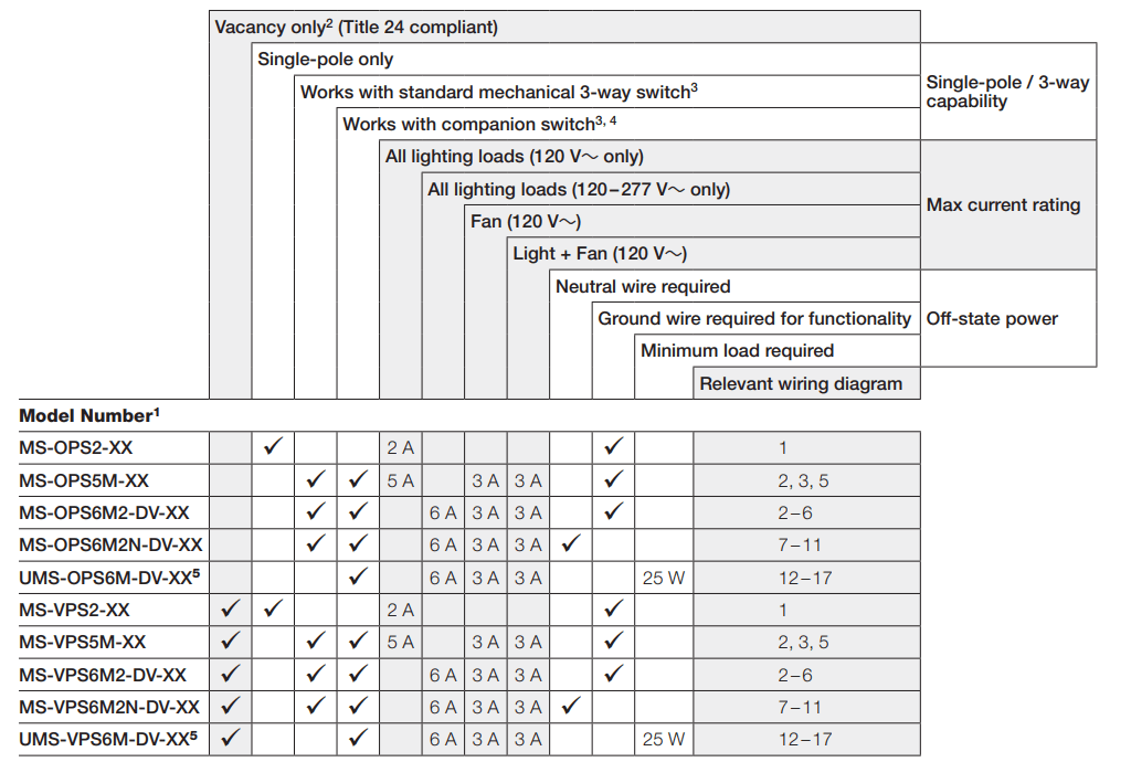
Selection Matrix
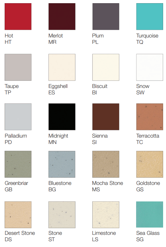
XX in model number represents color/finish code.
Occupancy sensors can be configured as Auto-ON / Auto-OFF or Manual-ON / Auto-OFF. Vacancy sensors are configured as Manual-ON / Auto-OFF only.
Standard mechanical 3-way switch cannot be combined with companion switch.
Companion switch MA-AS, MSC-AS, MA-AS-277, or MSC-AS-277 is required for multi-location installations (more than two locations controlling the same lighting circuit). Up to nine companion switches may be connected.
BAA-compliant models.
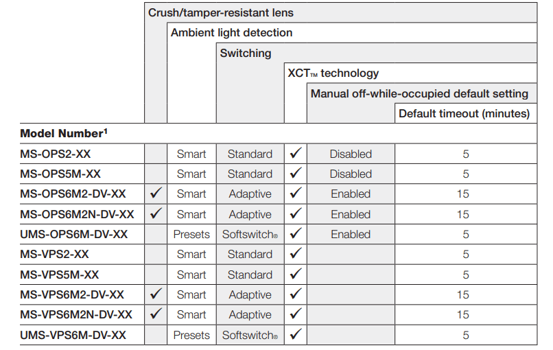
Additional Features
XX in model number represents color/finish code.
Occupancy Sensing Switch Placement and Operation
The ability of the Occupancy sensing switch to detect motion requires line-of-sight of room occupants. The Occupancy sensing switch must have an unobstructed view of the room.
Hot objects and moving air currents can affect the performance of the Occupancy sensing switch.
The performance of the Occupancy sensing switch depends on a temperature differential between the ambient room temperature and that of room occupants. Warmer rooms may reduce the ability of the Occupancy sensing switch to detect occupants.
Definitions
Major motion:movement of a person entering or passing through an area.
Minor motion: movement of a person occupying an area and engaging in small activities (e.g., reaching for a telephone, turning the pages of a book, opening a file folder, picking up a coffee cup).
NEMA WD7 Coverage
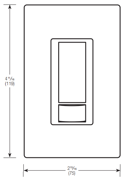
Dimensions
Measurements shown as: in (mm).
Front View
Side View
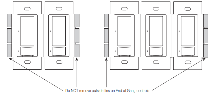
Ganging
When ganging with other controls in the same wallbox, remove inside fins (UMS-OPS6M-DV and UMS-VPS6M-DV only).
Each control has inside fins removed
Middle of Gang control has all fins removed
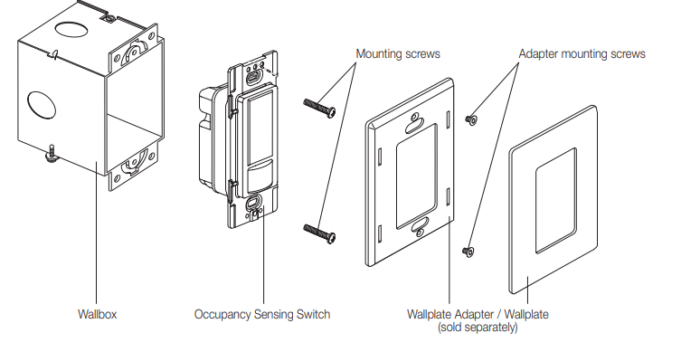
Mounting
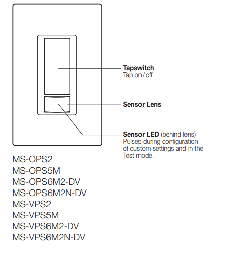
Operation
Important notice FASSTM—Front Accessible Service Switch— To service load, remove power by pulling the FASSTM switch out completely on either the Dimmer or Companion Dimmer. After servicing load, push the FASSTM switch back in fully to restore power to the control.
Wiring Diagrams
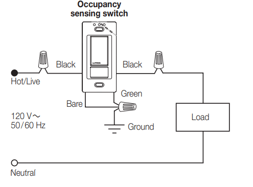
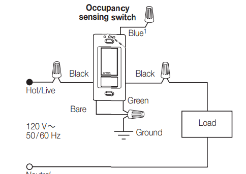
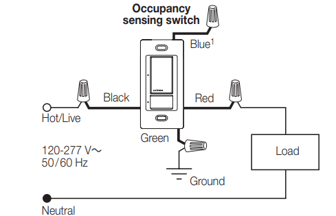
Wiring Diagram 1
Single Location Installation (120 V~)
-OPS2 and -VPS2
Wiring Diagram 2
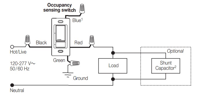
Single Location Installation (120 V ~)1
-OPS5M, -OPS6M2-DV, -VPS5M, -VPS6M2-DV
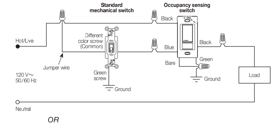
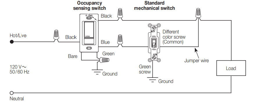
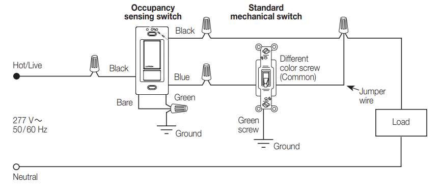
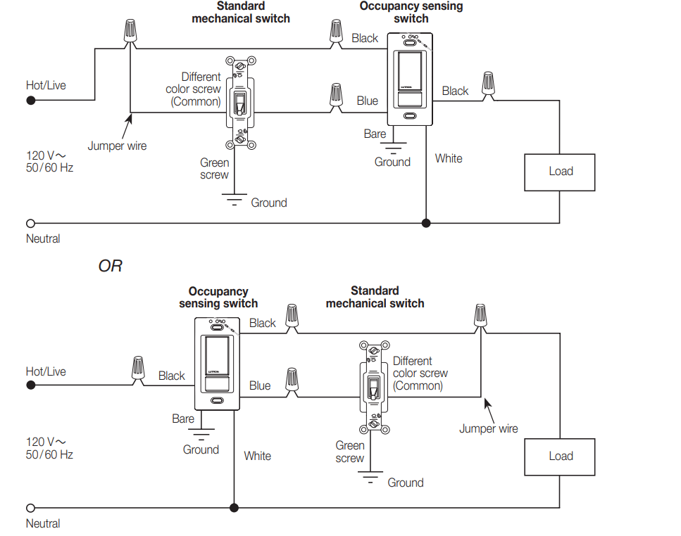
Wiring Diagram 3
3-way Installation with Standard Mechanical Switch (120 V~)2, 3
-OPS5M, -OPS6M2-DV, -VPS5M, -VPS6M2-DV
When using controls in single location installations, tighten the blue terminal or cap blue wire. Do not connect the blue terminal /wire to any other wire or to ground.
Only one Occupancy sensing switch can be used per multi-location circuit.
A single standard mechanical 3-way switch or up to 9 companion switches may be connected to most Occupancy sensing switches. Standard mechanical 3-way switch cannot be combined with companion switch. Total blue terminal wire length may be up to 150 ft (46 m).
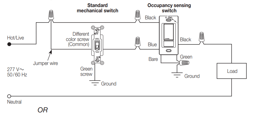
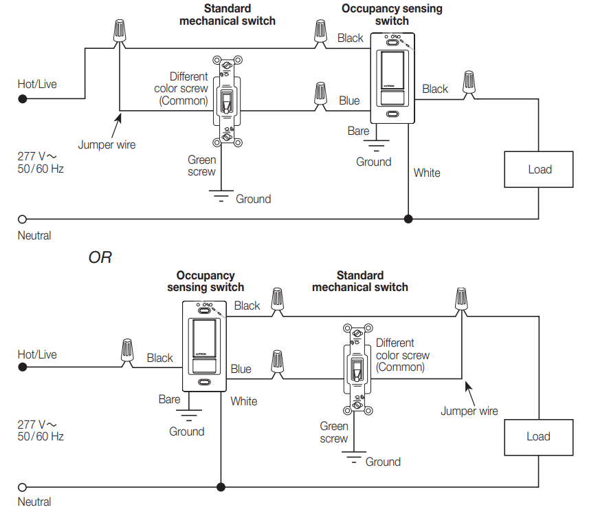
Wiring Diagram 4
3-way Installation with Standard Mechanical Switch (277 V~)1> 2 3
-OPS6M2-DV, -VPS6M2-DV
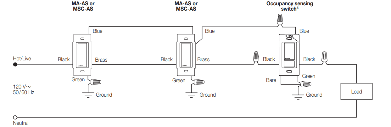
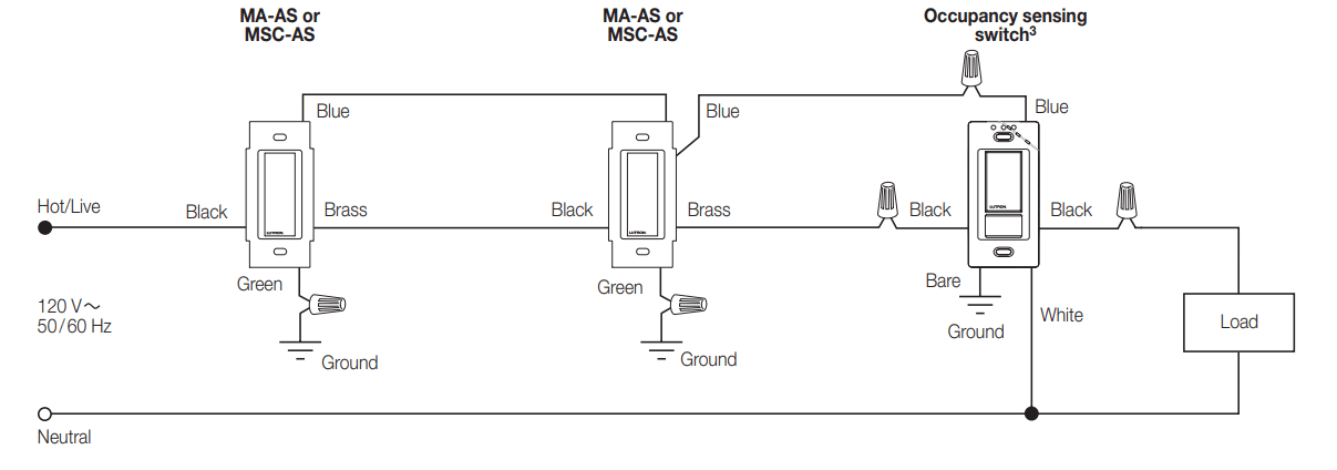
Wiring Diagram 5
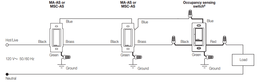
Multi-Location Installation (120 V~)1; 2 4
-OPS5M, -OPS6M2-DV, -VPS5M, -VPS6M2-DV with MA-AS or MSC-AS
A single standard mechanical 3-way switch or up to 9 companion switches may be connected to most Occupancy sensing switches. Standard mechanical 3-way switch cannot be combined with companion switch. Total blue terminal wire length may be up to 150 ft (46 m).
Only one Occupancy sensing switch can be used per multi-location circuit.
Fan load applies to 120 V~ only (not for 277 V~).
Occupancy sensing switch can be installed in any location.
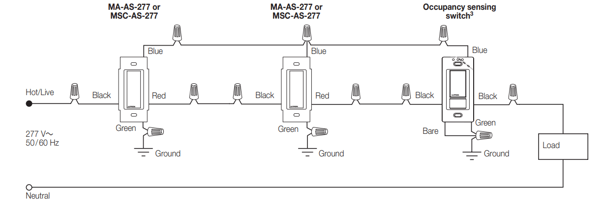
Wiring Diagram 6
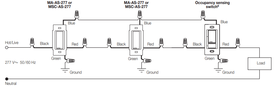
Multi-Location Installation (277 V~)1> 2 3 4
-OPS6M2-DV, -VPS6M2-DV with MA-AS-277 or MSC-AS-277
A single standard mechanical 3-way switch or up to 9 companion switches may be connected to most Occupancy sensing switches. Standard mechanical 3-way switch cannot be combined with companion switch. Total blue terminal wire length may be up to 150 ft (46 m).
Only one Occupancy sensing switch can be used per multi-location circuit.
Occupancy sensing switch can be installed in any location.
Fan load applies to 120 V~ only (not for 277 V~).
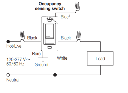
Wiring Diagram 7
Single Location Installation (120-277 V~)1> 2
-OPS6M2N-DV, -VPS6M2N-DV
Wiring Diagram 8
3-way Installation with Standard Mechanical Switch (120 V~)3> 4
-OPS6M2N-DV, -VPS6M2N-DV
When using controls in single location installations, tighten the blue terminal or cap blue wire. Do NOT connect the blue terminal /wire to any other wire or to ground.
Fan load applies to 120 V~ only (not for 277 V~).
Only one Occupancy sensing switch can be used per multi-location circuit.
A single standard mechanical 3-way switch or up to 9 companion switches may be connected to most Occupancy sensing switches. Standard mechanical 3-way switch cannot be combined with companion switch. Total blue terminal wire length may be up to 150 ft (46 m).
Wiring Diagram 9
3-way Installation with Standard Mechanical Switch (277 V~)1> 2 3
-OPS6M2N-DV, -VPS6M2N-DV
Only one Occupancy sensing switch can be used per multi-location circuit.
A single standard mechanical 3-way switch or up to 9 companion switches may be connected to most Occupancy sensing switches. Standard mechanical 3-way switch cannot be combined with companion switch. Total blue terminal wire length may be up to 150 ft (46 m).
Fan load applies to 120 V~ only (not for 277 V~).
Wiring Diagram 10
Multi-Location Installation (120 V~V’ 2’ 3
-OPS6M2N-DV, -VPS6M2N-DV with MA-AS or MSC-AS
Wiring Diagram 11
Multi-Location Installation (277 V~V’ 2’ 3’ 4
-OPS6M2N-DV, -VPS6M2N-DV with MA-AS-277 or MSC-AS-277
A single standard mechanical 3-way switch or up to 9 companion switches may be connected to most Occupancy sensing switches. Standard mechanical 3-way switch cannot be combined with companion switch. Total blue terminal wire length may be up to 150 ft (46 m).
Only one Occupancy sensing switch can be used per multi-location circuit.
Occupancy sensing switch can be installed in any location.
Fan load applies to 120 V~ only (not for 277 V~).
Wiring Diagram 12
Single Location Installation1’ 2
-OPS6M-DV and -VPS6M-DV
Wiring Diagram 13
Single Location Installation with Shunt Capacitor1, 2 3
-OPS6M-DV and -VPS6M-DV
Wiring Diagram 14
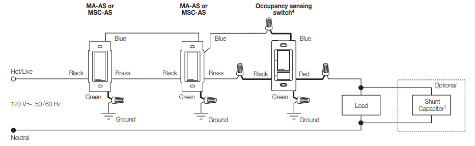
Multi-Location Installation (120 V^)1’4’ 5 6
-OPS6M-DV and -VPS6M-DV with MA-AS or MSC-AS
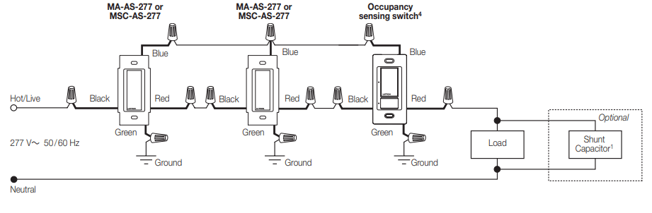
Wiring Diagram 15
Multi-Location Installation (277 V~V’ 2 3’ 4’ 5 6
-OPS6M-DV and -VPS6M-DV with MA-AS-277 or MSC-AS-277
When using controls in single location installations, tighten the blue terminal or cap blue wire. Do not connect the blue terminal /wire to any other wire or to ground.
Fan load applies to 120 V~ only (not for 277 V~).
Optional shunt capacitor must be installed inside the load fixture or in a separate J-box.
Up to 9 companion switches may be connected to an Occupancy sensing switch. Total blue terminal wire length may be up to 250 ft (76 m).
Only one Occupancy sensing switch can be used per multi-location circuit.
Occupancy sensing switch can be installed in any location. Continued on next page...
Wiring Diagram 16
Multi-Location Installation with Shunt Capacitor (120 V^)1’ 2’ 3’ 4