Lutron Electronics Co., Inc.
7200 Suter Road
Coopersburg, PA 18036-1299, U.S.A.
Please read before installing | Lea antes de realizar la instalación
C
•
L®
Sensor Dimmer | Sensor con Atenuador
When using CFLs or LEDs with this dimmer, only bulbs marked or rated as DIMMABLE and on the compatible list can be used.
For a complete list of compatible DIMMABLE CFLs and LEDs please visit www.lutron.com/dimcflled | For questions call 1.800.523.9466.
1. CAUTION: Use only with permanently installed xtures with dimmable screw-in compact uorescent, dimmable screw-in LED, halogen, or incandescent lamps. To avoid overheating and possible damage
to other equipment, do not use to control receptacles, motor-driven appliances, low-voltage lamps, or transformer supplied appliances.
2. Install in accordance with all national and local electrical codes.
3. When no “grounding means” exist in wallbox, the 2011 National Electrical CodeR (NECR) allows a control to be installed as a replacement if 1) a nonmetallic, noncombustible faceplate is used with
non-metallic attachment screws or 2) the circuit is protected by a ground fault circuit interrupter (GFCI). When installing a control according to these methods, cap or remove green wire before
screwing control into wallbox and use an appropriate wallplate such as ClaroR or Satin ColorsR series wallplates by Lutron.
4. The sensor requires an unobstructed view of the room to work properly.
5. Once power has been restored, the sensor will not automatically control the load for the rst 2 minutes.
6. MaestroR Sensor C•LR Dimmers ARE compatible with standard mechanical switches in 3-way applications only; requires additional setup and programming. See step 9, “Two-Locations Using
Existing Switch” on reverse side.
7. When using MaestroR Companion Dimmers in a 3-way / 4-way circuit you can use up to 9 MaestroR Companion Dimmers (MA-R, MSC-AD), but only one MaestroR Sensor C•LR Dimmer.
8. For incandescent and halogen loads do not use where total wattage is less than 10 W or greater than wattage indicated on the unit. For CFL / LED loads refer to the Lutron compatible lamp list at
www.lutron.com/dimcled.
9. For indoor use only between 32 °F and 104 °F (0 °C and 40 °C).
10. MaestroR Sensor C•LR Dimmers may feel warm to the touch during normal operation.
11. Maximum wire length between the Dimmer and the last MaestroR Companion Dimmer (MA-R, MSC-AD) or 3-Way switch is 150 ft (46 m).
12. Clean dimmers with a soft damp cloth only. Do not use any chemical cleaners.
IMPORTANT NOTES
READ FIRST
INSTALLATION
MSCL-OP153M 120 V~ 60 Hz
MSCL-VP153M 120 V~ 60 Hz
MAXIMUM ALLOWABLE WATTAGE
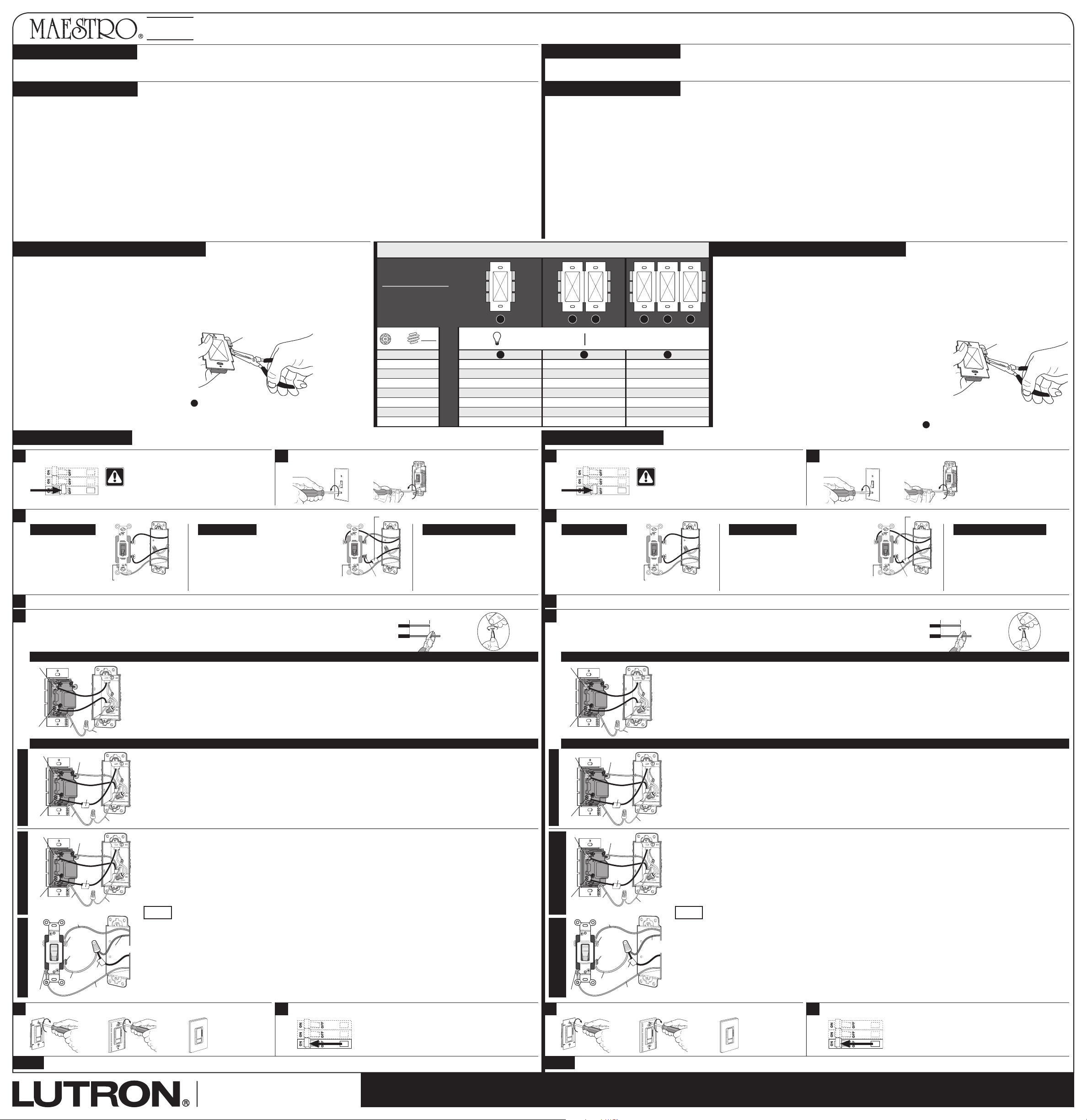
Determine allowable wattage (W) of dimmer by following the steps below. If multiple dimmers are to be installed
adjacently in the same wallbox, derating is required.
Derating Chart
1. Determine total wattage of CFL/LED bulbs installed for dimmer control.
2. Determine total wattage of Incandescent/Halogen bulbs to be controlled by the dimmer.
3. Use the Derating Chart to determine if your total wattages are within the allowable range of your configuration.
4. Derating Procedure
(if necessary)
If multiple dimmers are installed adjacently in the
same wallbox, heat fins MUST be removed between
adjacent dimmers. This will permanently derate the
dimmer, reducing its total allowable Incandescent/
Halogen wattage.
Example
If heat fins from one side of dimmer are removed (see
B
in chart) and you have two 24 W CFL bulbs installed
(Total CFL Wattage = 48 W), you may add up to 300W of Incandescent or Halogen lighting.
24/7 Help 1.800.523.9466 U.S.A. , Canada , Caribbean | E.U.A. , Caribe Ayuda +1.888.235.2910 México +1.610.282.3800 Others | Otros
Total W CFL/LED
+
A B C
0 W 10 W – 600 W 10 W – 500 W 10 W – 400 W
1 W – 25 W 0 W – 500 W 0 W – 400 W 0 W – 300 W
26 W – 50 W 0 W – 400 W 0 W – 300 W 0 W – 200 W
51 W – 75 W 0 W – 300 W 0 W – 200 W 0 W – 100 W
76 W – 100 W 0 W – 200 W 0 W – 100 W 0 W – 50 W
101 W – 125 W 0 W – 100 W 0 W – 50 W 0 W
126 W – 150 W 0 W 0 W 0 W
Derating Chart | Tabla de Reducción de la Capacidad Normal
Placing dimmers adjacent
to mechanical switches
does not require derating.
La colocación de
atenuadores junto a
interruptores mecánicos no
requiere de la reducción de
la capacidad normal.
A B CB B B
INC / HAL
A B C
LED
DEL
LFCA
CFL
LFCA
CFL
LED
DEL
1
WARNING: Shock Hazard. May result in
serious injury or death. Turn off power at
circuit breaker before installing the unit.
Turn power OFF at circuit breaker (or remove fuse).
Tag this wire
Different colored screw
(Common)
Disconnect the wires from the switches that are to be replaced.
Wire the new controls.
For installations involving more than one control in a wallbox, refer to Derating Chart above before beginning.
• Use the screw or push-in terminals when making connections on the dimmer or companion dimmer.
• Wire all controls before mounting.
For additional information visit www.lutron.com/dimcflled.
Mount dimmers to wallbox and install wallplate.
3
Identify the circuit type.
One switch controls
the lights, and will have
insulated wires connected
to 2 screws (same color)
and a green ground screw.
See step 5a when wiring.
3a - Single-Location
Two switches control the lights. You will need to TAG
the wire connected to the different colored screw (not
green) on both switches to identify when wiring a
mechanical switch or companion dimmer.
See step 5b when wiring.
3b - Two-Location
Requires MA-R Maestro® companion
dimmer for 3 or more locations.
Please visit:
www.lutron.com/
maestrosensorinstall
for additional wiring instructions.
3c - Three- or More Location
Ground
(Bare Copper or Green Wire)
Ground
(Bare Copper or Green Wire)
4
5
6
Note
Remove wallplate & switches (but do not disconnect wires).
2
Turn power ON at circuit breaker (or replace fuse).
7
Continue with steps 8 and 9 on reverse side.
3/8 in
(10 mm)
Twist wire
connector
tight.
For Push-In
Terminals
trim wires.
5a - Single-Location
5b - Two-Location
Wiring the Dimmer:
• Connect the green ground wire on the dimmer to the bare copper or green ground wire in the wallbox. (See Important Note 3)
• Connect either of the wires removed from the switch to the black screw terminal on the dimmer.
• Connect the remaining wire removed from the switch to the brass screw terminal on the dimmer.
• Tighten the blue screw terminal on the dimmer.
Black
screw
Ground
Green
wire
Brass screw
Wiring the Dimmer:
• Connect the green ground wire on the dimmer to the bare copper or green ground wire in the wallbox. (See Important Note 3)
• Connect the tagged wire removed from the switch to the black screw terminal on the dimmer.
• Connect one of the remaining wires removed from the switch to the brass screw terminal on the dimmer.
• Connect the remaining wire removed from the switch (note wire color) to the blue screw terminal on the dimmer.
Location 1 dimmerLocation 2 Companion dimmer Location 2 Existing Switch
OR
Re-Wire Existing 3-Way Mechanical Switch (required):
• Ensure the bare copper or green ground wire from the wallbox is connected to the green ground screw of the mechanical switch.
(See Important Note 3)
• Identify the wire that matches the color of the wire you connected to the blue screw of the MaestroR Dimmer. Connect this wire to Terminal 1
of the switch as shown.
• Combine the tagged wire, the remaining wire and the 14 AWG (1. 5 mm
2
) jumper wire (included) using a wire connector.
• Connect the other end of jumper wire to the different color screw.
• Additional programming required, see step 9 "Two-Locations using Existing Switch" after step 7.
IMPORTANT NOTE: For three or more locations, you must use companion dimmers. Please refer to additional wiring information, at:
www.lutron.com/maestrosensorinstall.
Tagged
Wire
Ground
Ground
Screw
Different
Color
Screw
Wire from Blue
Screw of Dimmer
Terminal
1
Remaining
Wire
Jumper
Wire
Ground
Tagged
wire
Black
screw
Brass screw
Blue
screw
Green
wire
Ground
Tagged
wire
Black
screw
Brass screw
Blue
screw
Green
wire
Incandescent / Halogen
Total Wattage
Incandescente / Halógena
Potencia Total
Occupancy / Presencia:
Vacancy / Vacancia:
Wiring the Companion Dimmer (MA-R, MSC-AD):
• Connect the green ground wire on the companion dimmer to the bare copper or green ground wire in the wallbox. (See Important Note 3)
• Connect the tagged wire removed from the switch to the black screw terminal on the companion dimmer.
• Connect the same color wire connected to the blue screw terminal on the dimmer (wire color noted above) to the blue screw terminal on the
companion dimmer.
• Connect the remaining wire removed from the switch to the brass screw terminal on the companion dimmer.
Heat Fins
INSTALACIÓN
1
ADVERTENCIA: Peligro de descarga eléctrica. Puede
ocasionar lesiones graves o la muerte. Desconecte la
alimentación en el cortacircuitos antes de instalar la
unidad.
Desconecte la alimentación en el cortacircuitos (o retire el fusible).
Rotule este cable
Tornillo de color distinto
(común)
Desconecte los cables de los interruptores que se reemplazarán.
Cablee los controles nuevos.
Para instalaciones de más de un control en una caja de empotrar, consulte la Tabla de reducción de la capacidad normal
que gura arriba antes de comenzar.
• Use los terminales a presión o de tornillo al realizar conexiones en el atenuador o atenuador accesorio.
• Cablee todos los controles antes del montaje. Para obtener información adicional, visite www.lutron.com/dimcflled.
Monte los atenuadores a la caja de empotrar e instale la placa de pared.
3
Identifique el tipo de circuito.
Un interruptor controla
las luces y tendrá cables
aislados conectados a 2
tornillos (del mismo color)
y un tornillo verde a tierra.
Vea el paso 5a para
cablear.
3a - Ubicación única
Dos interruptores controlan las luces. Deberá
ROTULAR el cable conectado al tornillo de color
distinto (no verde) en ambos interruptores para
identificar el cableado de un interruptor mecánico o
un atenuador accesorio.
Vea el paso 5b para cablear.
3b - Dos ubicaciones
Se requiere un atenuador accesorio
Maestro® MA-R para 3 ubicaciones o más.
Visite: www.lutron.com/
maestrosensorinstall para
obtener instrucciones de cableado
adicionales.
3c - Tres ubicaciones o más
Tierra (cable de cobre sin
aislamiento o cable verde)
Tierra (cable de cobre sin
aislamiento o cable verde)
4
5
6
Nota
Retire la placa de pared y los interruptores (pero no desconecte los
cables).
2
Conecte la energía en el cortacircuitos (o reemplace el fusible).
7
Continúe con los pasos 8 y 9 que se encuentran al dorso.
10 mm
(3/8 in)
Gire el
conector de
cable para
ajustarlo.
Para los
terminales
a presión,
recorte los
cables.
5a - Ubicación única
5b - Dos ubicaciones
Cableado del atenuador:
• Conecte el cable verde a tierra del atenuador al cable de cobre sin aislamiento o al cable verde a tierra de la caja de empotrar. (Consulte la Nota
importante 3)
• Conecte cualquiera de los cables extraídos del interruptor al terminal de tornillo negro del atenuador.
• Conecte el cable restante extraído del interruptor al terminal de tornillo color latón del atenuador.
• Ajuste el terminal de tornillo azul del atenuador.
Tornillo
negro
Tierra
Cable
verde
Tornillo color latón
Cableado del atenuador:
• Conecte el cable verde a tierra del atenuador al cable de cobre sin aislamiento o al cable verde a tierra de la caja de empotrar. (Consulte la Nota
importante 3)
• Conecte el cable rotulado extraído del interruptor al terminal de tornillo negro del atenuador.
• Conecte uno de los cables restantes extraídos del interruptor al terminal de tornillo color latón del atenuador.
• Conecte el cable restante extraído del interruptor (tenga en cuenta el color del cable) al terminal de tornillo azul del atenuador.
Ubicación 1 AtenuadorUbicación 2
Atenuador accesorio
Ubicación 2
Interruptor existente
O
Vuelva a cablear el interruptor mecánico de 3 vías existentes (requerido):
• Asegúrese de que el cable de cobre sin aislamiento o el cable verde a tierra de la caja de empotrar esté conectado al tornillo verde a
tierra del interruptor mecánico. (Consulte la Nota importante 3)
• Identifique el cable del mismo color que el cable que conectó al tornillo azul del atenuador MaestroR. Conecte este cable al Terminal 1 del
interruptor como se muestra.
• Combine el cable rotulado, el cable restante y el cable de 1,5mm
2
(14 AWG) de puente (incluido) utilizando un conector de cable.
• Conecte el otro extremo del cable de puente al tornillo de color distinto.
• Se requiere programación adicional; consulte el paso 9 “Dos ubicaciones que utilizan el interruptor existente” después del paso 7.
NOTA IMPORTANTE: Para tres o más ubicaciones, debe utilizar atenuadores accesorios. Consulte la información de cableado adicional en:
www.lutron.com/maestrosensorinstall.
Cable
rotulado
Tierra
Tornillo
a tierra
Tornillo
de color
distinto
Cable del tornillo
azul del atenuador
Terminal
1
Cable
restante
Cable de
puente
Tierra
Cable
rotulado
Tornillo
negro
Tornillo color
latón
Tornillo
azul
Cable
verde
Tierra
Cable
rotulado
Tornillo
negro
Tornillo color latón
Tornillo
azul
Cable
verde
Cableado del atenuador accesorio (MA-R, MSC-AD):
• Conecte el cable verde a tierra del atenuador accesorio al cable de cobre sin aislamiento o al cable verde a tierra de la caja de empotrar.
(Consulte la Nota importante 3)
• Conecte el cable rotulado extraído del interruptor al terminal de tornillo negro del atenuador accesorio.
• Conecte el cable del mismo color que el conectado al terminal de tornillo azul del atenuador (arriba se indica el color del cable) al terminal de
tornillo azul del atenuador accesorio.
• Conecte el cable restante extraído del interruptor al terminal de tornillo color latón del atenuador accesorio.
POTENCIA MÁXIMA PERMITIDA
Para determinar la potencia permitida (W) del atenuador, siga los pasos a continuación. Si se instalan varios
atenuadores de manera contigua en la misma caja de empotrar, se requiere de la reducción de la capacidad
normal.
Tabla de reducción de la capacidad normal
1. Determine la potencia total de los focos LFCA o LED instalados para el control de atenuación.
2. Determine la potencia total de los focos incandescentes o halógenos que controlará el atenuador.
3. Utilice la Tabla de reducción de la capacidad normal para determinar si las potencias totales están dentro del
rango permitido de su configuración.
4. Procedimiento de reducción de la capacidad
normal
(si es necesario)
Si se instalan varios atenuadores de manera contigua en la misma
caja de empotrar, se DEBEN extraer las aletas de calor entre los
atenuadores contiguos. Esto reducirá la capacidad normal de
manera permanente y disminuirá la potencia total incandescente o
halógena permitida.
Ejemplo
Si las aletas de calor de un lado del atenuador se extrajeron (vea
B
en la tabla) y tiene dos focos LFCA de 24W
instalados (potencia total de LFCA = 48W), puede agregar hasta 300W de iluminación incandescente o halógena.
Aletas de calor
Cuando emplee focos LFCA o LED con este atenuador, sólo podrá utilizarlos si están marcados o clasicados como ATENUABLES y en la lista compatible.
Para obtener una lista completa de focos LFCA o LED ATENUABLES compatibles, visite www.lutron.com/dimcflled | Si tiene alguna pregunta, llame al 1.888.235.2910.
1. PRECAUCIÓN: Utilizar únicamente con luminarias de instalación ja y con los siguientes focos roscados y atenuables: uorescentes compactos autobalastrados, LED y halógenos o incandescentes. Para
evitar recalentamientos y posibles daños a otros equipos, no lo utilice para controlar receptáculos, ni electrodomésticos a motor o con transformador ni lámparas de bajo voltaje.
2. Realice la instalación de acuerdo con todos los códigos eléctricos nacionales y locales.
3. Cuando dentro de la caja de empotrar no hay “medios de conexión a tierra”, el National Electrical CodeR (NECR) 2011 permite la instalación de un control como reemplazo, siempre y cuando 1)
se utilice una placa frontal plástica e incombustible con tornillos de jación no metálicos o 2) el circuito se encuentre protegido por un interruptor de circuitos de fallas de conexión a tierra (GFCI).
Al instalar un control de acuerdo con estos métodos, cubra el cable verde o retírelo antes de atornillar el control en la caja de empotrar, y use una placa de pared apropiada, como las de la serie
ClaroR o Satin ColorsR de Lutron.
4. El sensor requiere una vista de la habitación sin obstrucciones para funcionar correctamente.
5. Cuando se restablece la energía, el sensor no controlará automáticamente la carga durante los primeros dos minutos.
6. Los atenuadores MaestroR Sensor C•LR SON compatibles con interruptores mecánicos estándar en aplicaciones de 3 vías únicamente. Se requiere de conguración y programación adicionales.
Consulte el paso 9, “Dos ubicaciones que utilizan el interruptor existente” al dorso.
7. Al utilizar los atenuadores accesorios MaestroR en un circuito de 3 o 4 vías, puede usar hasta 9 atenuadores accesorios MaestroR (MA-R, MSC-AD), pero sólo un atenuador MaestroR Sensor C•LR.
8. Para cargas incandescentes y halógenas, no utilice el atenuador si la potencia total es inferior a los 10W o superior a la potencia que se indica en la unidad. Para cargas LFCA / LED, consulte la
lista de lámparas compatibles con Lutron en www.lutron.com/dimcled.
9. Sólo para uso en interiores a una temperatura de entre 0 °C y 40 °C (32 °F y 104 °F).
10. Es posible que los atenuadores MaestroR Sensor C•LR se sientan tibios al tacto durante su operación normal.
11. El largo máximo del cable entre el atenuador y el último atenuador accesorio MaestroR (MA-R, MSC-AD) o el interruptor de 3 vías es de 46m (150pies).
12. Limpie los atenuadores con un paño suave y húmedo solamente. No use productos químicos de limpieza.
NOTAS IMPORTANTES
LEA PRIMERO
8 DIMMING RANGE ADJUSTMENT
(Válida solamente en E.U.A., Canadá, Puerto Rico y el Caribe.)
Lutron reparará o reemplazará, a su criterio, cualquier unidad que presente fallas en sus materiales o fabricación dentro del año
posterior a su compra. Para obtener el servicio de garantía, devuelva la unidad al lugar donde la adquirió o envíela a Lutron,
7200 Suter Rd., Coopersburg, PA 18036-1299 E.U.A., con servicio postal prepago.
Esta garantía reemplaza a toda otra garantía expresa; la garantía implícita de comerciabilidad está limitada a
un año desde la fecha de compra. Esta garantía no cubre el costo de instalación, de remoción ni de reinstalación, ni
daños causados por uso incorrecto o abuso, ni daños resultantes de un cableado o una instalación incorrectos. Esta
garantía no cubre daños incidentales ni indirectos.
LA RESPONSABILIDAD DE LUTRON ANTE UNA DEMANDA POR DAÑOS DEBIDOS A LA FABRICACIÓN, VENTA, INSTALACIÓN,
ENTREGA O USO DE LA UNIDAD, O RELACIONADOS CON ESTOS PROCESOS, NO EXCEDERÁ EN NINGÚN CASO EL PRECIO
DE COMPRA DE LA UNIDAD.
La presente garantía le otorga derechos legales especí cos, pero podría tener también otros derechos que varían según el estado.
Algunos estados no permiten la exclusión o limitación de los daños incidentales o indirectos, ni limitaciones en la duración de
las garantías implícitas, de modo que dichas limitaciones pueden no ser aplicables en su caso.
Lutron, Maestro, C•L, Claro, y Satin Colors son marcas registradas y FASS es una marca comercial de Lutron Electronics Co., Inc.
NEC es una marca registrada de National Fire Protection Association, Quincy, Massachusetts. © 2012 Lutron Electronics Co., Inc.
(Valid only in the U.S.A., Canada, Puerto Rico, and the Caribbean.)
Lutron will, at its option, repair or replace any unit that is defective in materials or manufacture within
one year after purchase. For warranty service, return unit to place of purchase or mail to Lutron at 7200
Suter Rd., Coopersburg, PA 18036-1299, postage pre-paid.
This warranty is in lieu of all other express warranties, and the implied warranty of merchantability
is limited to one year from purchase. This warranty does not cover the cost of installation, removal
or reinstallation, or damage resulting from misuse, abuse, or damage from improper wiring or
installation. This warranty does not cover incidental or consequential damages.
LUTRON’S LIABILITY ON ANY CLAIM FOR DAMAGES ARISING OUT OF OR IN CONNECTION WITH
THE MANUFACTURE, SALE, INSTALLATION, DELIVERY, OR USE OF THE UNIT SHALL NEVER EXCEED
THE PURCHASE PRICE OF THE UNIT.
This warranty gives you speci c legal rights, and you may have other rights which vary from state to state.
Some states do not allow the exclusion or limitation of incidental or consequential damages, or limitation
on how long an implied warranty may last, so the above limitations may not apply to you.
Lutron, Maestro, C•L, Claro, and Satin Colors are registered trademarks and FASS is a trademark
of Lutron Electronics Co., Inc. NEC is a registered trademark of the National Fire Protection Association,
Quincy, Massachusetts. © 2012 Lutron Electronics Co., Inc.
WARRANTY GARANTIÁ LIMITADA
Lutron Electronics Co., Inc.
7200 Suter Road
Coopersburg, PA 18036-1299, U.S.A.
w
w
w
.
l
u
t
r
o
n
.
c
o
m
0301660
Rev. A
12/2012
Lutron Electronics Co., Inc.
0301660
Rev. A
12/2012
LED
DEL
LFCA
CFL
150 W
Compact Fluorescent (CFL) / LED
Lampara Fluorescente Compacto
Autobalastrado (LFCA) / LED
600 W
Incandescent / Halogen
Incandescente / Halógena
INC / HAL
MSCL-OP153M
MSCL-VP153M
120 V~ 60 Hz
0301660
Rev. A
12/2012
MSCL-OP153M
MSCL-VP153M
0301660
Rev. A
12/2012
C
•
L®
www.lutron.com
Sensor Dimmer
Sensor con Atenuador
Symptoms/Issues Solution(s)
Lights don't turn off after immediate room departure. Default Timeout is 5 minutes after last detected motion; see Timeout Adjustment in Programming section.
Do not want the lights to turn on when entering the room. See Auto-On Adjustment in Programming section to change sensor behavior.
After manual shutoff, lights will not automatically turn back on. When Auto-On is enabled, sensor ignores motion for 25 seconds after manual shutoff. The sensor may also be in OWO or ALD mode;
see Auto-On Adjustment in Programming Section.
Lights perform incorrectly at low dim levels. Verify bulbs are rated as dimmable an on the compatible list (www.lutron.com/dimc led); perform installation step 8, Dimming
Range Adjustment.
Two-Location (3-Way) application is not functioning correctly. – Verify wiring is correct (see step 5b, wiring differs from typical 3-Way).
– Verify programming is correct (see step 9, Two-Location Using Existing Switch section).
Lights seem to be turning on when the room is unoccupied. Hot objects or moving air currents can affect performance. See Sensitivity Adjustment in Programming section.
TROUBLESHOOTING
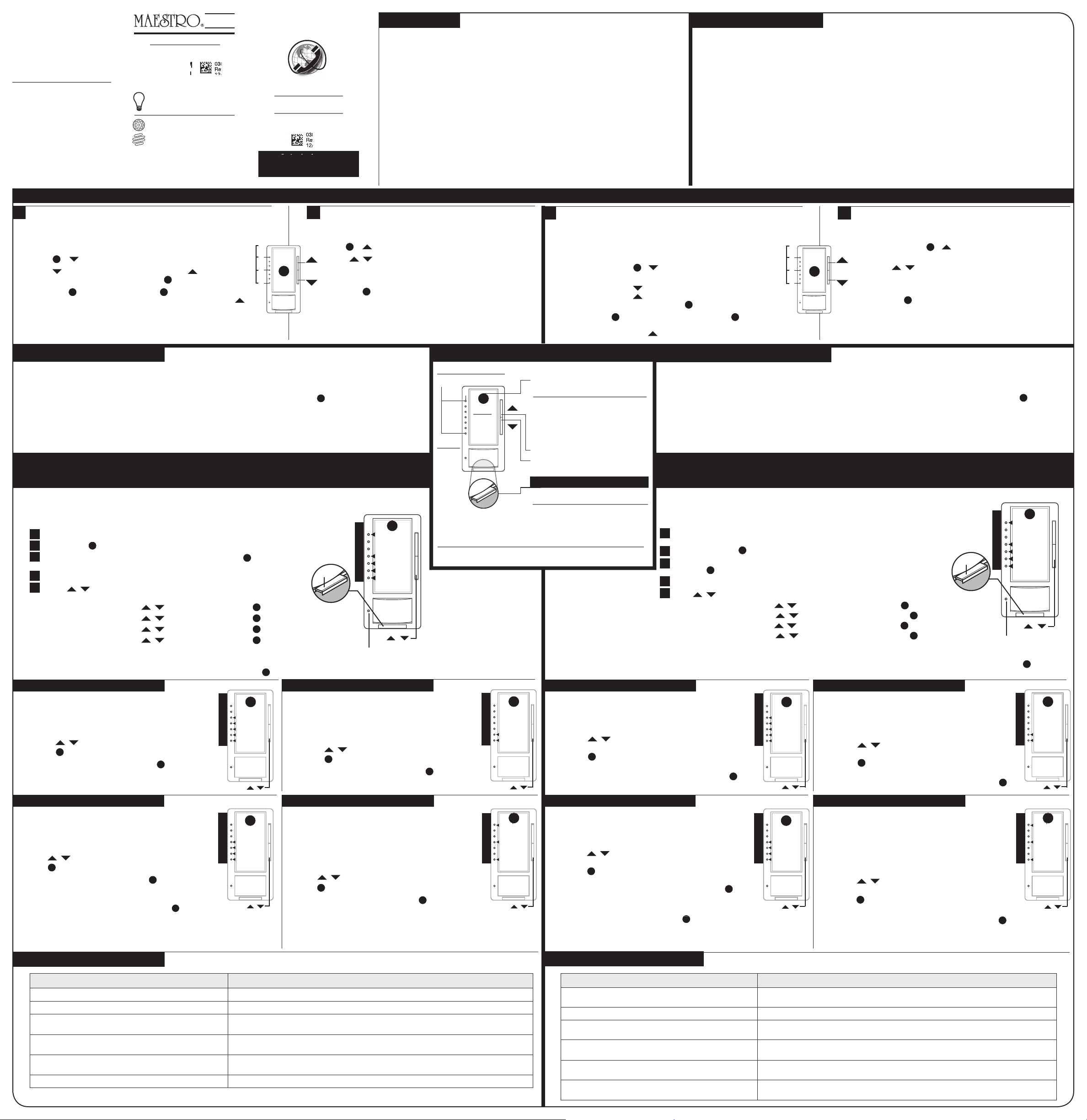
Raise Lights | Subir luces
Tap Button:
Tap once to turn lights on to preset level.
Tap again to turn lights off. Double tap to
turn light on to full intensity.
Botón de presión:
Toque una vez para encender las luces en
el nivel predefinido. Toque otra vez para
apagar las luces. Toque dos veces para
encender la luz a la intensidad máxima.
Lower Lights | Bajar luces
T
Indicator Lights (IL)
Luces indicadoras (IL)
7
1
Indicates
light level
Indica
nivel de
luz
Tap
Presion
FASSTM
Front Accessible -
Service Switch
Interruptor de
servicio de
acceso frontal
used to temporarily disconnect
power to the light fixture
- se utiliza para desconectar la
alimentación a la luminaria
temporalmente
Note: Upon startup or disconnecting of power, there will be a 2 minute calibration
period before normal operation.
Nota: En la puesta en servicio o al desconectar el suministro eléctrico, habrá un
período de calibración de 2 minutos antes del funcionamiento normal.
OPERATION | OPERACIÓN
IL
/
4 Occupied Lvl
3 Auto-on
2 Sensitivity
1 Timeout
Sensor IL
FASSTM
**
Main Menu – Changing Sensor Features
Pull FASST out, into OFF position. (Remove faceplate if FASST cannot be accessed easily.)
Press and hold
T
.
Push the FASST back in to the ON position, while continuing to hold
T
for
approximately 5 seconds. Release when IL 1 is blinking quickly.
You are now in Programming Mode.
Use the
/ to change the blinking IL to the feature you would like to modify.
(See Diagram to right)
A. Timeout Use
/ until IL 1 is blinking, Press
T
go to A. below.
B. Sensitivity Use
/ until IL 2 is blinking, Press
T
go to B. below.
C. Auto-On * Use
/ until IL 3 is blinking, Press
T
go to C. below.
D. Occupied Level * Use
/ until IL 4 is blinking, Press
T
go to D. below.
*
MSCL-OP153M Only
Note: If there is no activity for one minute, dimmer will exit Programming Mode automatically.
1
2
3
4
5
A. Timeout Adjustment
D. Occupied Level Adjustment
B. Sensitivity Adjustment
C. Auto-On Adjustment
MSCL-OP153M version only.
MSCL-OP153M version only.
Note: Default setting is 5 minutes.
Timeout = Duration of time the sensor will wait to turn off the
lights after the space is vacated.
To change Timeout:
1. Press
/ to move blinking IL to desired selection.
2. Press
T
once to set time. You will return to main menu.
To exit Programming Mode, press and hold
T
for 5 seconds.
Note: Default setting is 100% light level.
Occupied Level = The light level your sensor will turn on to
when motion is detected.
Preset = Lights will turn on to the last light level used, or to a
locked preset (if that has been selected).
To change Occupied Light Level:
1. Press
/ until lights in room are at desired level.
2. Press
T
once to set light level. You will return to main menu.
To exit Programming Mode, press and hold
T
for 5 seconds.
Note: Default setting is High Sensitivity.
Sensitivity = The sensitivity of the sensor can be lowered if
the sensor is being triggered falsely by alternate heat sources
in the room.
To change Sensitivity:
1. Press / to move blinking IL to desired selection.
2. Press
T
once to set mode. You will return to main menu.
To exit Programming Mode, press and hold
T
for 5 seconds.
T
IL
5 30 minutes
4 15 minutes
3 5 minutes
2 3 minutes
1 1 minute
/
/
T
IL
7 100%
4 50%
1 Preset
/
100%
100%
T
IL
2 High
1 Low
/
T
IL
4 OWO Mode
†
3 ALD Mode *
2 Disabled
1 Enabled
/
T
Note:
When using CFLs or LEDs with this
dimmer, only bulbs marked or rated
as DIMMABLE and on the compatible
list can be used. For a complete list of
compatible DIMMABLE CFLs and LEDs
please visit www.lutron.com/dimcflled
Two-Location Using Existing Switch
Dimming Range Adjustment
If dimming range of bulbs is satisfactory, save these instructions for future
reference, otherwise follow the steps below.
To Change Dimming Range:
1. Hold
T
& until an indicator light (IL) blinks.
2. Hold until indicator light (IL 1) is reached. Hold until all bulbs
are on and stable (no ickering). Single tap
T
to save setting.
3. Single tap
T
to turn off bulbs. Single tap
T
again. If all bulbs do not turn
on or are not stable, repeat step 1, and in step 2 increase light with .
If using a mechanical switch in a two-location application, the following
programming is required on the dimmer:
1. Hold
T
& until an indicator light (IL) blinks.
2. Using / , select an option:
(IL) 1, if a mechanical switch is being used.
(IL) 4, if a companion dimmer is being used.
3. Single tap
T
to save setting.
Or
7
1
T
8 9
4
** Please visit
www.lutron.com/
maestrosensorinstall
for
additional programming
information.
The MaestroR Sensor C•LR Dimmer (occupancy or vacancy) has many features to allow you to set the unit to meet your individual needs. Key
features include: Timeout Adjustment, Sensitivity Adjustment, Auto-On Adjustment
*, Occupied Level Adjustment *.
SENSOR PROGRAMMING
(OPTIONAL)
Your dimmer is ready to use as is; below are some
additional features for advanced programming that
are not required for normal use.
MSCL-OP153M – Sensor automatically turns lights on when space is occupied, and off when space is vacated.
See C. Auto-On Adjustment for Occupancy Mode changes.
MSCL-VP153M – Lights must be manually turned on. Sensor automatically turns lights off when space is vacated.
Note: For either Sensor version, the lights can also be manually turned off at any time by pressing
T
on the Dimmer.
Manual Off: Exit Time Delay (Only when Auto-On is Enabled)
After the unit is manually turned off, the auto-on feature will be disabled for 25 seconds, even if motion is detected. This is to provide
occupants time to exit larger rooms after manually turning the lights off. The unit can be manually turned on at any time. After
25 seconds, the unit will return to normal operation.
SENSOR FUNCTIONALITY
INSTALLATION (continued)
Restore Factory Settings: Execute steps 1-3 of Programming Mode but hold
T
for 15 seconds instead of 5 seconds in step 3.
Note: Default setting is Enabled.
Auto-On = Lights will turn on when motion is detected.
This can be disabled.
To change Auto-On:
1. Press
/ to move blinking IL to desired selection.
2. Press
T
once to set mode. You will return to main menu.
To exit Programming Mode, press and hold
T
for 5 seconds.
* ALD (Ambient Light Detect) Mode: Sensor only turns on lights when motion is detected
and ambient light is too low. If lights turn on when there is enough natural light, or if
lights do not turn on when there is not enough natural light, press
and ambient light is too low. If lights turn on when there is enough natural light, or if
T
within 5 seconds
of entering the room. Over time, this interaction will "teach" the sensor your preferred
setting. Please visit www.lutron.com/maestrosensorinstall for applications and details.
IL
Please visit www.lutron.com/maestrosensorinstall for additional troubleshooting information.
† OWO (Off While Occupied) Mode: Please visit www.lutron.com/maestrosensorinstall
for applications and details.
U.S.A. | Canada | Caribbean
E.U.A. | Caribe
1.800.523.9466
México
+1.888.235.2910
Others | Otros
+1.610.282.3800
Fax
+1.610.282.6311
Nota:
Cuando emplee focos LFCA o LED con
este atenuador, sólo podrá utilizarlos
si están marcados o clasi cados
como ATENUABLES y en la lista
compatible. Para obtener una lista
completa de focos ATENUABLES LFCA
y LED compatibles, visite
www.lutron.com/dimcflled.
Dos ubicaciones que utilizan el interruptor existente
Ajuste del rango de atenuación
Si el rango de atenuación de los focos es satisfactorio, guarde estas
instrucciones para referencia futura; de lo contrario, siga los pasos a
continuación.
Para cambiar el rango de atenuación:
1. Mantenga presionado
T
y hasta que una luz indicadora (IL)
parpadee.
2. Mantenga presionado hasta alcanzar la luz indicadora (IL 1).
Mantenga presionado hasta que todos los focos estén encendidos y
estables (sin parpadear). Toque una vez
T
para guardar la con guración.
3. Toque una vez
T
para apagar los focos. Vuelva a tocar
T
una vez. Si no
encienden todos los focos o no están estables, repita el paso 1, y en el
paso 2, aumente la luz con .
Si utiliza un interruptor mecánico en una aplicación de dos
ubicaciones, se requiere la siguiente programación en el atenuador:
1. Mantenga presionado
T
y hasta que una luz indicadora (IL)
parpadee.
2. Utilizando / , seleccione una opción:
(IL) 1, si se utiliza un interruptor mecánico.
(IL) 4, si se utiliza un atenuador accesorio.
3. Un solo toque
T
para guardar la con guración.
O
7
1
T
8 9
4
INSTALACIÓN (continuación)
IL
MSCL-OP153M – El sensor enciende las luces automáticamente cuando el espacio está ocupado y las apaga cuando el espacio queda vacío.
Consulte C. Ajuste del encendido automático para cambios del modo de presencia.
MSCL-VP153M – Las luces se deben encender manualmente. El sensor apaga las luces automáticamente cuando el espacio queda vacío.
Nota: En cualquiera de las dos versiones del sensor, las luces también pueden apagarse a mano en cualquier momento al presionar
T
en el atenuador.
Apagado manual: Retardo del tiempo de salida (sólo cuando encendido automático es Habilitado)
Después de apagar la unidad manualmente, se deshabilitará la característica de encendido automático durante 25 segundos aunque se
detecte algún movimiento. Esto es para darle tiempo a los ocupantes para salir de habitaciones más grandes después de apagar las luces
automáticamente. La unidad se puede encender de forma manual en cualquier momento. Después de 25 segundos, la unidad volverá a su
funcionamiento normal.
FUNCIONALIDAD DEL SENSOR
Síntomas / Problemas Soluciones
Las luces no se apagan de forma inmediata después de salir de la habitación. La desconexión por tiempo predeterminada es de 5 minutos después del último movimiento detectado; consulte Ajuste de
desconexión por tiempo en la sección Programación.
Se desea que las luces permanezcan apagadas al ingresar a la habitación. Consulte Ajuste del encendido automático en la sección Programación para cambiar el comportamiento del sensor.
Después del apagado manual, las luces no se volverán a encender automáticamente. Cuando encendido automático es habilitado, el sensor ignora el movimiento durante 25 segundos después del apagado manual.
El sensor tambien puede estar en modo OWO o ALD; vea Ajuste del encendido automático en la sección Programación.
Las luces funcionan de manera incorrecta en niveles bajos de atenuación. Veri que que los focos sean atenuables y se encuentren en la lista compatible (www.lutron.com/dimc led); lleve a cabo el paso de
instalación 8, Ajuste del rango de atenuación.
La aplicación de dos ubicaciones (3 vías) no está funcionando correctamente. – Veri que que el cableado esté correcto (consulte el paso 5b, el cableado di ere del cableado típico de 3 vías).
– Veri que que la programación sea la correcta (consulte el paso 9, sección Dos ubicaciones que utilizan el interruptor existente).
Las luces parecen encenderse cuando la habitación está vacía. Los objetos vivos o las corrientes de aire pueden afectar el funcionamiento. Consulte Ajuste de sensibilidad en la sección
Programación.
RESOLUCIÓN DE PROBLEMAS
Visite www.lutron.com/maestrosensorinstall para obtener más información sobre la resolución de problemas.
IL
4 Nivel de presencia
3 Encendido automático
2 Sensibilidad
1 Desconexión
por tiempo
Sensor IL
FASSTM
**
Menú principal – Cambio de las características del sensor
Deslice el interruptor FASST hacia la posición de APAGADO . (Retire la placa frontal si no se
puede tener acceso al interruptor FASST fácilmente).
Mantenga presionado
T
.
Vuelva a colocar el FASST en la posición de ENCENDIDO, mientras sigue manteniendo
presionado
T
durante aproximadamente 5 segundos. Suelte cuando IL 1 parpadee rápidamente.
Ahora está en modo de programación.
Use el
/ para cambiar IL a la característica que desea modi car. (Consulte el diagrama a la derecha)
A. Desconexión por tiempo Use
/ hasta que IL 1 parpadee, Presione
T
vaya a A. a continuación.
B. Sensibilidad Use
/ hasta que IL 2 parpadee, Presione
T
vaya a B. a continuación.
C. Encendido automático * Use
/ hasta que IL 3 parpadee, Presione
T
vaya a C. a continuación.
D. Nivel de presencia * Use
/ hasta que IL 4 parpadee, Presione
T
vaya a D. a continuación.
*
MSCL-OP153M solamente
Nota: Si no hay actividad durante un minuto, el atenuador saldrá del modo de programación automáticamente.
1
2
3
4
5
A. Ajuste de desconexión por tiempo
D. Ajuste del nivel de presencia
B. Ajuste de sensibilidad
C. Ajuste del encendido automático
Versión MSCL-OP153M solamente.
Versión MSCL-OP153M solamente.
Nota: La con guración predeterminada es 5 minutos.
Desconexión por tiempo = Tiempo que el sensor espera para
apagar las luces cuando el espacio queda vacío.
Para cambiar la desconexión por tiempo:
1. Presione
/ para cambiar el indicador IL que parpadea
a la selección deseada.
2. Presione
T
una vez para con gurar el tiempo. Volverá al
menú principal.
Para salir del modo de programación, mantenga presionado
T
durante 5 segundos.
Nota: La co guración predeterminada es nivel de luz al 100%.
Nivel de presencia = El nivel de luz en el que se encenderá el
sensor cuando se detecte algún movimiento.
Nivel prede nido = Las luces se encenderán según el último
nivel de luz usado o en un nivel prede nido bloqueado (si se
seleccionó).
Para cambiar el nivel de luz de presencia:
1. Presione
/ hasta que las luces de la habitación
alcancen el nivel deseado.
2. Presione
T
una vez para de nir el nivel de luz. Volverá al menú
principal.
Para salir del modo de programación, mantenga presionado
T
durante 5 segundos.
Nota: La con guración predeterminada es Sensibilidad Alta.
Sensibilidad = La sensibilidad del sensor se puede bajar si el
sensor se dispara de manera incorrecta debido a fuentes de
calor alternativas en la habitación.
Para cambiar la sensibilidad:
1. Presione / para cambiar el indicador IL que parpadea
a la selección deseada.
2. Presione
T
una vez para con gurar el modo. Volverá al
menú principal.
Para salir del modo de programación, mantenga presionado
T
durante 5 segundos.
T
IL
5 30 minutos
4 15 minutos
3 5 minutos
2 3 minutos
1 1 minuto
T
IL
7 100%
4 50%
1 Nivel
prede nido
100%
100%
T
IL
2 Alta
1 Baja
T
IL
4 OWO
†
3 ALD*
2 Deshabilitado
1 Habilitado
T
** Visite
www.lutron.com/
maestrosensorinstall
para obtener más
información sobre
programación.
El atenuador MaestroR Sensor C•LR (presencia o vacancia) tiene muchas características que le permiten con gurar la unidad para satisfacer
sus necesidades individuales. Las características principales incluyen: Ajuste de desconexión por tiempo, Ajuste de
sensibilidad, Ajuste de encendido automático
*, Ajuste de nivel de presencia *.
PROGRAMACIÓN DEL
SENSOR (OPCIONAL)
El atenuador está listo para usarse tal como está; a continuación,
encontrará algunas características adicionales para la
programación avanzada que no se requieren para el uso habitual.
Restablecer la con guración de fábrica: Ejecute los pasos 1 a 3 del modo de programación pero mantenga presionado
T
durante
15 segundos en lugar de 5 segundos en el paso 3.
Nota: La con guración predeterminada es Habilitado.
Encendido automático = Las luces se encenderán cuando se detecte
algún movimiento. Esta característica se puede deshabilitar.
Para cambiar el encendido automático:
1. Presione
/ para cambiar el indicador IL que parpadea a la
selección deseada.
2. Presione
T
una vez para con gurar el modo. Volverá al menú
principal.
Para salir del modo de programación, mantenga presionado
T
durante 5 segundos.
* Modo ALD (Detección de luz ambiental): el sensor sólo enciende las luces cuando detecta algún
movimiento y la luz ambiental es demasiado baja. Si las luces se encienden cuando hay su ciente luz natural, o no
se encienden cuando no hay su ciente luz natural, presione
movimiento y la luz ambiental es demasiado baja. Si las luces se encienden cuando hay su ciente luz natural, o no
movimiento y la luz ambiental es demasiado baja. Si las luces se encienden cuando hay su ciente luz natural, o no
T
dentro de los 5 segundos de haber ingresado a la
habitación. Con el tiempo, esta interacción le “enseñará” al sensor cuál es su preferencia. Visite www.lutron.com/
maestrosensorinstall para obtener información sobre aplicaciones y más detalles.
† Modo OWO (Apagar mientras está ocupado): Visite www.lutron.com/maestrosensorinstall para obtener
información sobre aplicaciones y más detalles.
/
/ /
/ /