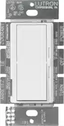
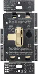
Lutron DV-600P-WH Diva Dimmer Switch for Incandescent Bulbs, 600-Watt/Single-Pole
Product's Documents
Below are documents related to this product, you can read online or download:
- Owner's manual - (English, Spanish) Read Online | Download pdf