Setup & Operation Instructions
Installation
Tools and Supplies Needed
- Phillips screwdriver
- Wire stripper
- Hammer
- Valve wire: direct burial, color coded multi-strand (not included)
- 18 gauge for runs less than 800 feet.
- 14 gauge for runs greater than 800 feet.
- Watertight splice connectors (not included)
Step 1. Mount Timer
Mount the SST in an accessible location
NOTE: SST indoor timers are for indoor use only. SST outdoor timers can be used indoors or outdoors.
1 For indoor installation, choose a location within 5 feet of an AC power outlet and at least 15 feet away from major appliances or air conditioners.
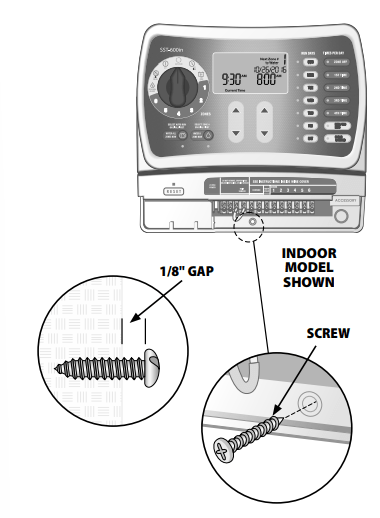
2 Drive a screw into the wall, leaving an 1/8" gap between the screw-head and the wall (use the supplied wall anchors if necessary).
3 Locate the keyhole slot on back of the unit and hang it securely on the screw.
4 Remove the wiring bay cover at the bottom of the unit and drive a screw through the center hole as shown (use the supplied wall anchors if necessary).
Step 2. Connect Power
WARNING: DO NOT plug in or apply power to the timer until you have completed and checked all wiring connections.
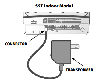
Indoor Timer
- Attach the transformer connector to the 24VAC POWER pin connection on the terminal strip
WARNING: Do not attempt to link two or more timers together using a single transformer.
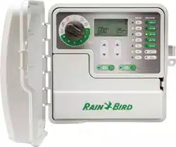
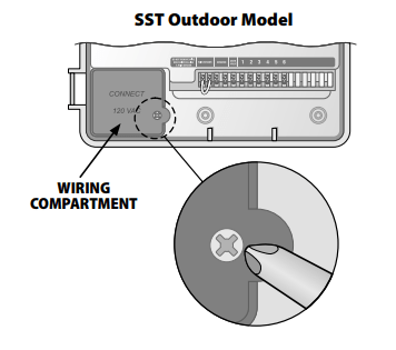
Outdoor Timer
Standard Installation
The SST outdoor version comes with a power cord and 24VAC transformer already connected.
Hard-wire Installation
WARNING: Disconnect or shut off the external power source before connecting or disconnecting wires to the timer.
1 Remove the wiring bay cover at the bottom of the unit.
2 Locate the wiring compartment in the lower left-hand corner of the unit and using a screwdriver, unscrew wiring compartment front cover.
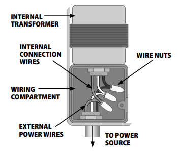
4 Unscrew the wire-nuts from the three wires connecting the power cord to the timer.
5 Remove the metal bracket holding the power cord to the back of the wiring compartment and pull the cord out through the bottom of the cabinet.
6 Route the three wires from an external power source into the wiring compartment.
7 Using the wire-nuts, connect the external power wires to the internal connection wires inside the wiring compartment
WARNING: Be sure to connect the color coded external wires to the same color internal connection wires, as follows:
- Black wire (power)
- White wire (neutral)
- Green wire (ground)
7 Verify that all wiring connections are secure, then replace the wiring compartment cover
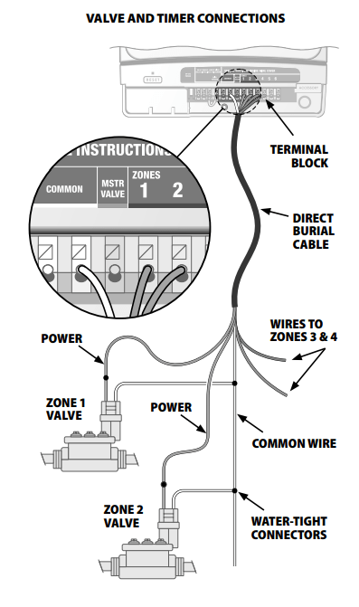
Step 3. Connect Valve Wires To Timer
Valve Connections
1 Use direct burial cable to run wiring from the timer to valves in the field.
2 Connect a color coded wire from the direct burial cable to either wire on the valve.
3 Connect the remaining wire on each valve to a “common" wire which then connects to the timer.
NOTE: Use water-tight connectors for all wire splice connections. Depending on your landscape setup, you may need to run extension wires for the power and common connections.
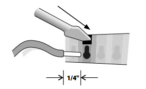
Timer Connections
Use a wire stripper to strip away approximately 1/4" of insulation from the end of the valve wire.
2 Push the exposed end of the color coded wire from each external valve (or zone) into the corresponding zone number on the terminal block
NOTE: To insert or remove a wire, use a screwdriver to press down on the connection release.
WARNING: To prevent damage to the timer, connect only ONE valve to each open zone slot on the terminal block.
3 Connect the common wire to one of the COMMON slots on the terminal block.
4 Check that all wiring connections are secure.
NOTE: Do not remove the yellow jumper wire on the terminals marked RAIN SENSOR unless you’re connecting an optional rain sensor. See "Rain Sensor" on page 3 for more information
Step 4. Verify System Operation
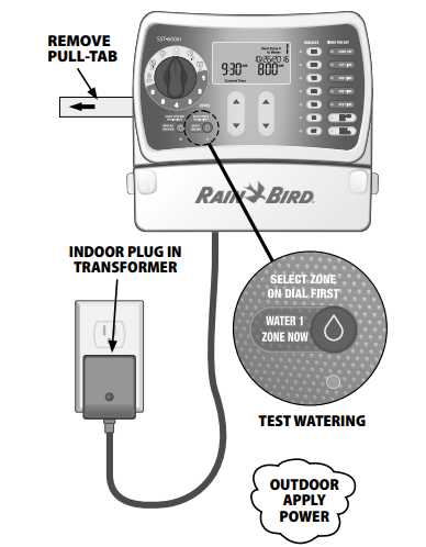
Battery Pull Tab
- To activate the internal battery, grasp the yellow pull-tab on the side of the timer and pull it out.
NOTE: If the timer doesn’t have AC power for more than a week, the time needs to be reset. This conserves battery power for future outages. Program details are kept in long term non volatile memory so they are not lost even after long power outages.
Apply Power
Indoor Model
- Plug the transformer into a wall outlet.
Outdoor Model
- Turn on main power supply or plug the power cord into a waterproof receptacle
NOTE: Do not plug the timer into a socket that is controlled by a secondary ON/OFF light switch or GFI outlet.
Test Watering
1 Turn the dial to the ZONE 1 position.
 Press the WATER 1 ZONE NOW button. The zone will start watering for the default run time of 10 minutes and the green LED corresponding to WATER 1 ZONE NOW button turns on.
2 To stop watering before time is up, press the WATER 1 ZONE NOW button a second time. The green LED corresponding with the WATER 1 ZONE NOW button will turn off.
3 Repeat the above steps until all connected zones have been tested.
4 Replace the wiring bay cover on front of the unit
Optional Accessories
Rain Sensor
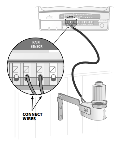
Connect an optional Rain Sensor to the Timer
Remove the wiring bay cover at the bottom of the unit.
2 Remove the yellow jumper wire from the terminals marked RAIN SENSOR on the terminal block.
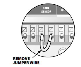
NOTE: Do not remove the jumper wire unless connecting a rain sensor. The timer will not function if the jumper wire is removed and a rain sensor is not connected.
3 Connect the two wires from the sensor to the RAIN SENSOR terminals.
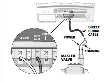
Master Valve Or Pump Start Relay
Connect an optional master valve or pump start relay
SST timers support the use of a master valve or pump start relay. A pump start relay connects to the timer the same way as a master valve, but connects differently at the water source.
Using a direct burial cable, connect one of the wires from the master valve (or pump start relay) to the timer terminal marked MSTR VALVE.
2 Using a direct burial cable, connect the remaining wire from the master valve (or pump start relay) to one of the timer terminals marked COMMON.
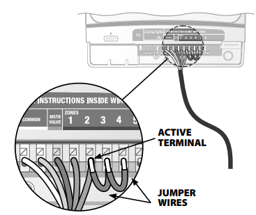
Additional instructions for connecting a pump start relay
- To avoid possible pump damage, connect a short jumper wire from any unused zone terminal(s) to the previous terminal, continuing back to the nearest zone terminal in use (as shown below). For example, if a 4 zone model timer is in use with only two zones connected, route the terminals for zones 3 and 4 to the nearest active terminal (zone 2 in the example below).
WARNING: Make sure that the total draw of the master valve (and/or pump start relay) plus the draw of the valve does not exceed 650mA at 24VAC, 60hz. Note that the timer does NOT provide main power for a pump
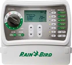
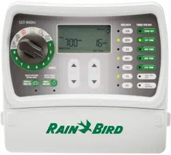
Controls and Indicators
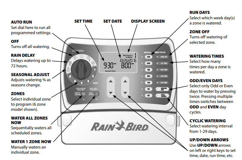
Setting the Timer
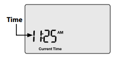
Step 1. Set Time
 Turn the dial to the SET TIME position
Press the UP/DOWN arrow keys to set the time (verify AM/PM setting is correct).
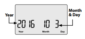
Step 2. Set Date
Turn the dial to the SET DATE position.
Press the LEFT UP/DOWN arrow keys to set the year.
Press the RIGHT UP/DOWN arrow keys to set the month and day.
Step 3. Schedule Wateringg
Turn the dial to select the desired ZONE (from 1 to 12).
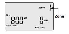
Set Start Time and Run Time
Press the Left UP/DOWN arrow keys to set the Start Time.
Press the Right UP/DOWN arrow keys to set the Run Time (duration).
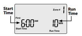
NOTE: Multiple zones having the same start time will run in sequence by zone number. For example, if zones 3 and 4 are both set to run for 10 min. at 8:00 AM, zone 3 will run first at 8:00 then zone 4 will run afterward at 8:10
Select Run Days
Press the RUN DAYS buttons to select which days to water. Active watering days will show lights illuminated.
NOTE: By default ALL days are lit. Press the button(s) to turn off the days you don't want to water.
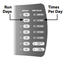
Select specific days of the week or select ODD /EVEN DAYS or CYCLIC WATERING.
When ODD/EVEN DAYS is pressed
1st press will show Odd Days on the screen
2nd press will show Even Days on the screen.
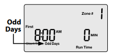
NOTE: When Odd Days or Even Days is first pressed it will flash a few times on the screen and then stay illuminated.
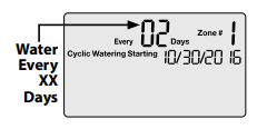
When CYCLIC WATERING is pressed:
Press the LEFT UP/DOWN arrow keys to increase or decease the number of days between watering (EVERY XX DAYS).
Press the RIGHT UP/DOWN arrow keys to adjust the Cyclic Watering start date.
Select Watering Times Per Day
Press the TIMES PER DAY buttons to schedule the number of times per day to water.
Press the LEFT UP/DOWN arrow keys to set the Start Time.
Press the RIGHT UP/DOWN arrow keys to set the Run Time (duration).
- Repeat Step 3 for remaining zones.
Turn the dial to AUTO RUN.
Optional Features
Multiple Start Times
After selecting a time per day the screen will show that time, “First", as an example.
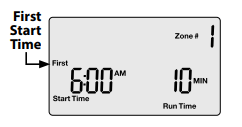
Press the LEFT UP/DOWN arrow keys to set the start time.
Press the RIGHT UP/DOWN arrow keys to set the duration.
- Repeat to set additional watering times, up to 4 per day
NOTE: If a second, third, or fourth watering time is scheduled earlier in time than a previous time, the timer will automatically reorder the times sequentially the next time the dial is turned to that zone #
Seasonal Adjust
Adjust for seasonal weather variation
Turn the dial to SEASONAL ADJUST.
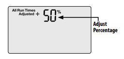
Press the UP/DOWN arrow keys to adjust the percentage. For example, a +50% adjustment means 10 min. becomes 15 min.
NOTE: Adjustment applies to ALL watering run times (durations) for all zones.
Rain Delay
Suspend Watering
Turn the dial to RAIN DELAY.
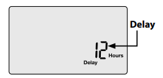
Press the UP/DOWN arrow keys to set the delay time for up to 3 days (72 hours).
NOTE: Any scheduled watering that falls within the delay period will not occur.
Normal Operation
While set to AUTO RUN, one of the following screens will be displayed:
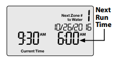
Not Watering
Screen displays the current time, the zone that is scheduled to be watered next, and the date and time when watering will occur.
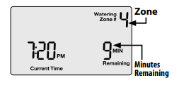
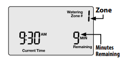
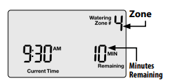
Watering Now
Screen displays the zone currently being watered and the number of minutes remaining for that zone.
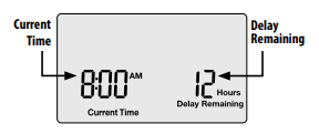
Rain Delay
Screen displays the current time and the number of delay hours that are left until regularly scheduled watering resumes.
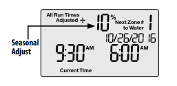
Seasonal Adjust
Screen displays the percentage adjustment for all zones.
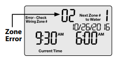
Error
Detected If an error is detected, the affected zone is displayed.
Important! Always return the dial to AUTO RUN when programming is completed. The timer will not run automatically unless the dial is set to AUTO RUN.
Manual Operation
Choose from two Manual Watering options:

Water All Zones Now
Turn the dial to AUTO RUN.
Press the WATER ALL ZONES NOW button to start watering.
Screen displays which zone is being watered and the number of minutes remaining for that zone.
To stop watering the active zone and skip to next zone, press the WATER ALL ZONES NOW button again
To stop manual watering, turn the dial to OFF, wait until watering is stopped and then back to AUTO RUN.
Water 1 Zone Now
Turn the dial to select a ZONE.
Press the WATER 1 ZONE NOW button to start watering (default run time of 10 minutes).
Press the UP/DOWN arrow keys to adjust the run time
To stop manual watering, turn dial to OFF, wait until watering is stopped, and then turn dial to AUTO RUN, or press the Water 1 Zone Now button a second time.
Troubleshooting
Watering Issues
| Problem |
Possible Cause |
Possible Solution |
| Automatic and manual cycles do not begin watering. |
Water source not supplying water. |
Verify the main water and all supply lines are open and operating properly |
| |
Wires not properly connected. |
Verify field wires are connected properly including the timer, master valve (or pump start relay) and any spliced connections. |
| |
Wires damaged or corroded. |
Check field wiring for damage and replace if necessary. Check all connections and replace with watertight connectors as needed |
| |
Dial not set to AUTO RUN position. |
Turn the dial to set date and set time and use UP/Down arrows to set correct date and time. |
| |
Date and/or Time is not set correctly |
Enter the current Date and Time on the controller. |
| |
An installed Rain Sensor may be activated. |
Operation will resume when sensor dries out. To test operation, disconnect the Sensor and connect a jumper wire between the Rain Sensor terminals. |
| |
If no Rain Sensor is installed, the jumper wire may be damaged or missingAn installed Rain Sensor may be activated. |
Connect the two yellow Rain Sensor terminals with a short length of 14 to 18 gauge jumper wire. |
| |
An electrical surge may have damaged the timer’s electronics. |
Disconnect power to the timer for 3 minutes, press the reset button, then turn back on. If there is no damage, the timer will accept programming and resume normal operation. |
| Watering cycles do not shut off. |
Debris trapped in valve. |
Flush the valve by temporarily opening the bleed-screw and re-tighten. |
Electrical Issues
| Problem |
Possible Cause |
Possible Solution |
| LCD Display is blank. |
Timer is not receiving power. |
- Verify the power cord is connected and securely plugged in (indoor).
- Verify the transformer is wired correctly and the circuit breaker is on (outdoor).
|
| No red LED light on transformer (indoor only). |
Blown transformer. |
Replace transformer. |
| LCD Display is “frozen" and timer will not accept programming. |
An electrical surge may have damaged the timer’s electronic |
Disconnect power to the timer for 3 minutes, press the reset button, then turn back on. If there is no damage, the timer will accept programming and resume normal operation. |
| Valve short error message on LCD display |
Wires damaged or corroded. |
Check the indicated zone wiring for damage and replace if necessary. Check all connections and replace with watertight connectors as needed. |