User Manual
INSTALLATION
Installation Overview
Please read the following installation instructions first after purchasing this product or transporting it to another location.

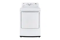
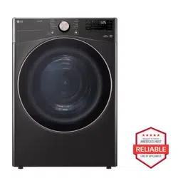
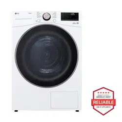
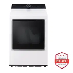
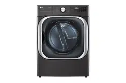
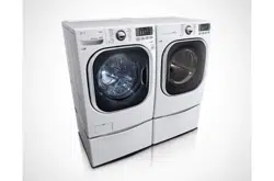
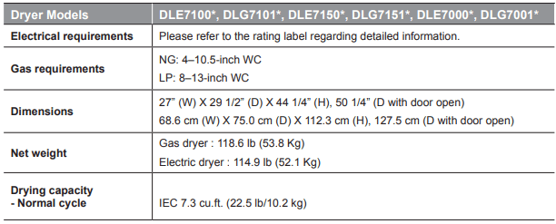
Product Specifications
The appearance and specifications listed in this manual may vary due to constant product improvements.
Installation Location Requirements
Warning
Read all installation instructions completely before installing and operating the dryer! It is important that you review this entire manual before installing and using the dryer. Detailed instructions concerning electrical connections, gas connections, and exhaust requirements are provided on the following pages.
The installation requires:
- A location that allows for proper exhaust installation. A gas dryer must be exhausted to the outdoors. See Venting the Dryer.
- A grounded electrical outlet located within 2 ft. (61 cm) of either side of the dryer. See Connecting Electric Dryers .
- A sturdy floor to support the total dryer weight of 200 lb (90.7 kg). The combined weight of a companion appliance should also be considered.
- No other fuel-burning appliance can be installed in the same closet as a dryer.
Do not operate the dryer at temperatures below 45 °F (7 °C). At lower temperatures, the dryer might not shut off at the end of an automatic cycle. This can result in longer drying times. The dryer must not be installed or stored in an area where it will be exposed to water and/or weather. Check code requirements. Some codes limit, or do not permit, installation of the dryer in garages, closets, mobile homes or sleeping quarters. Contact your local building inspector.
NOTE
- The floor must be level, with a maximum slope of 1 inch (2.5 cm) under the entire dryer. Clothes may not tumble properly, and automatic sensor cycles may not operate correctly if dryer is not level.
- For a garage installation, you will need to place the dryer at least 18 inches (46 cm) above the floor. The standard pedestal is 15 inches (38.1 cm). You will need 18 inches (46 cm) from the garage floor to the bottom of the dryer.
Clearances
Installation Spacing for Recessed Area or Closet Installation
The following spacing dimensions are recommended for this dryer. This dryer has been tested for clearances of inch (2.5 cm) on the sides and rear. Recommended clearances should be considered for the following reasons:
- Additional clearances should be considered for ease of installation and servicing.
- Additional clearances might be required for wall, door and floor moldings.
- Additional clearances should be considered on all sides of the dryer to reduce noise transfer. For closet installation, with a door, minimum ventilation openings in the top and bottom of the door are required. Louvered doors with equivalent ventilation openings are acceptable.
- Companion appliance spacing should also be considered.
Closet Ventilation Requirements
Closets with doors must have both an upper and lower vent to prevent heat and moisture buildup in the closet.
One upper vent opening with a minimum opening of 48 sq. in. (310 cm2 must be installed no lower than 6 feet above the floor. One lower vent opening with a minimum opening of 24 sq. in. (155 cm2 must be installed no more than one foot above the floor. Install vent grills in the door or cut down the door at the top and bottom to form openings. Louvered doors with equivalent ventilation openings are also acceptable.
Installation Spacing for Recessed Area or Closet

Installation Spacing for Cabinet
For cabinet installation with a door, minimum ventilation openings in the top of the cabinet are required.

Leveling the Dryer
1 Position the dryer in the final location. Check levelness of dryer from side to side. Repeat from front to back.

2 Use an adjustable wrench to turn the leveling feet. Unscrew the legs to raise the dryer or screw in the legs to lower it. Raise or lower with the leveling feet until the dryer is level from side to side and front to back. Make sure that all four leveling feet are in firm contact with the floor.

If you are installing the dryer on the optional pedestal, you must use the leveling feet on the pedestal to level the dryer. The dryer leveling feet should be fully retracted.
Reversing the Door
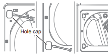
1 Open the door and remove the two plastic hole caps on the catch side by gently prying up with a flat blade screwdriver. Save these for step 6.
2 While supporting the door, remove the 4 screws, two from each hinge. Set the door aside face down on a protected surface to prevent damage to the door or the work surface.
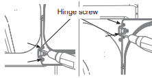
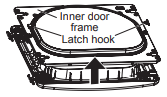
3 With the door on a protected surface, remove all screws on each side of the door and lift off the inner door frame using a flat blade screwdriver. Remove the latch hook and blank and move them to the opposite side.
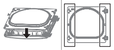
4 Remove the 4 screws securing the hinges to the door frame. Remove the two plastic cover caps. Reinstall the hinges and cover caps on the opposite sides from which they were removed.

5 With the hinges and cover caps in the new locations, remount the inner door frame onto the outer door frame with the screws removed in step 3 above.
6 Reinstall the door with the screws from steps 1,2.
7 Test the swing of the door to make sure the hinges and latch are properly aligned and that the door closes and latches correctly

Installing the Side Vent Kit
Warning
- Use a heavy metal vent.
- Do not use plastic or thin foil ducts.
- Clean old ducts before installing this dryer.
- To reduce the risk of injury to persons, adhere to all industry recommended safety procedures including the use of long-sleeved gloves and safety glasses.
- Failure to follow all of the safety warnings in this manual could result in property damage, injury to persons, or death.
The dryer is shipped to vent to the rear. It can also be configured to vent to the bottom or side (right-side venting is not available on gas models).
An adapter kit, part number 383EEL9001B, may be purchased from an LG retailer. This kit contains the necessary duct components to change the dryer vent location.
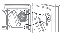
1 Remove the rear exhaust duct retaining screw. Pull out the exhaust duct.

Option 1: Side Venting
2 Press the tabs on the knockout and carefully remove the knockout for the desired vent opening (right-side venting is not available on gas models). Press the adapter duct onto the blower housing and secure to the base of the dryer as shown.

3 Preassemble a 4-inch (10.2 cm) elbow to the next 4-inch (10.2 cm) duct section, and secure all joints with duct tape. Be sure that the male end of the elbow faces AWAY from the dryer. Insert the elbow/duct assembly through the side opening and press it onto the adapter duct. Secure it in place with duct tape. Be sure that the male end of the duct protrudes 1½ inches cm) to connect the remaining ductwork. Attach the cover plate to the back of the dryer with the included screw.

Option 2: Bottom Venting
2 Press the adapter duct onto the blower housing and secure it to the base of the dryer as shown.

3 Insert the 4-inch (10.2 cm) elbow through the rear opening and press it onto the adapter duct. Be sure that the male end of the elbow faces down through the hole in the bottom of the dryer. Secure it in place with duct tape. Attach the cover plate to the back of the dryer with the included screw.

Venting the Dryer
Warning: To reduce the risk of fire or explosion, electric shock, property damage, injury to persons or death when using this appliance, follow basic safety precautions, including the following:
- Do not crush or collapse ductwork. Failure to follow these instructions may result in fire or death.
- Do not allow ductwork to rest on or contact sharp objects. Failure to follow these instructions may result in fire or death.
- If connecting to existing ductwork, make sure it is suitable and clean before installing the dryer. Failure to follow these instructions may result in fire or death.
- Venting must conform to local building codes.
- Failure to follow these instructions may result in fire or death.
- Gas dryers MUST exhaust to the outdoors.
- Failure to follow these instructions may result in fire or death.
- Use only 4-inch (10.2 cm) rigid, semi-rigid or flexible metal ductwork inside the dryer cabinet and for venting outside. Failure to follow these instructions may result in fire or death.
- To reduce the risk of fire, combustion, or accumulation of combustible gases, DO
- NOT exhaust dryer air into an enclosed and unventilated area, such as an attic, wall, ceiling, crawl space, chimney, gas vent, or concealed space of a building. Failure to follow these instructions may result in fire or death.
- To reduce the risk of fire, DO NOT exhaust the dryer with plastic or thin foil ducting. Failure to follow these instructions may result in fire or death.
- The exhaust duct must be 4 inches (10.2 cm) in diameter with no obstructions. The exhaust duct should be kept as short as possible. Make sure to clean any old ducts before installing your new dryer. Failure to follow these instructions may result in fire or death.
- Rigid, semi-rigid or flexible metal ducting is recommended for use between the dryer and the wall. All non-rigid metal transition duct must be UL-listed. Use of other materials for transition duct could affect drying time. Failure to follow these instructions may result in fire or death.
- DO NOT use sheet metal screws or other fasteners which extend into the duct that could catch lint and reduce the efficiency of the exhaust system. Secure all joints with duct tape. Failure to follow these instructions may result in fire or death.
- Do not exceed the recommended duct length limitations noted in the chart. Failure to follow these instructions may result in extended drying times, fire or death.
- Ductwork is not provided with the dryer. You should obtain the necessary ductwork locally.
- The vent hood should have hinged dampers to prevent backdraft when the dryer is not in use. Failure to follow these instructions may result in fire or death.
- The total length of flexible metal duct must not exceed 8 ft. (2.4 m).
- In Canada, only those foil-type flexible ducts, if any, specifically identified for use with the appliance by the manufacturer should be used.
- In the United States, only those foil-type flexible ducts, if any, specifically identified for use with the appliance by the manufacturer and that comply with the Outline for Clothes Dryer Transition Duct, Subject 2158A, should be used.
Ductwork

Routing And Connecting Ductwork
NOTE: Follow the guidelines below to maximize drying performance and reduce lint buildup and condensation in the ductwork. Ductwork and fittings are NOT included and must be purchased separately.
- Use 4-inch (10.2 cm) diameter rigid, semi-rigid or flexible metal ductwork.
- The exhaust duct run should be as short as possible.
- Use as few elbow joints as possible.
- The male end of each section of exhaust duct must point away from the dryer.
- Use duct tape on all duct joints.
- Insulate ductwork that runs through unheated areas in order to reduce condensation and lint buildup on duct surfaces.
- Incorrect or inadequate exhaust systems are not covered by the dryer warranty. Dryer failures or service required because of such exhaust systems will not be covered by the dryer warranty.
Correct Venting

Incorrect Venting

Connecting Gas Dryers
Warning: To reduce the risk of fire or explosion, electric shock, property damage, injury to persons, or death when using this appliance, follow basic safety precautions.
Gas Supply Requirements
- As shipped from the factory, this dryer is configured for use with natural gas (NG). It can be converted for use with propane (LP) gas. Gas pressure must not exceed 8 inches cm) of water column for NG, or 13 inches cm) of water column for LP.
- A qualified service or gas company technician must connect the dryer to the gas service. Failure to follow these instructions may result in fire, explosion, or death.
- Isolate the dryer from the gas supply system by closing its individual manual shutoff valve during any pressure testing of the gas supply. Failure to do so may result in fire, explosion, or death.
- Supply line requirements: Your laundry room must have a rigid gas supply line to the dryer. In the United States, an individual manual shutoff valve MUST be installed within at least 6 ft. (1.8 m) of the dryer, in accordance with the National Fuel Gas Code ANSI Z223.1 or Canadian gas installation code CSA B149.1. A 1/8-inch (0.3 cm) NPT pipe plug must be installed. Failure to do so may result in fire, explosion, or death.
- If using a rigid pipe, the rigid pipe should be 1/4 inch IPS. If acceptable under local codes and ordinances and when acceptable to your gas supplier, 3/8-inch (1 cm) approved tubing may be used where lengths are less than 20 ft. m). Larger tubing should be used for lengths in excess of 20 ft. (6.1 m). Failure to do so may result in fire, explosion, or death.
- Connect the dryer to the type of gas shown on the nameplate. Failure to do so may result in fire, explosion, or death.
- To prevent contamination of the gas valve, purge the gas supply of air and sediment before connecting the gas supply to the dryer. Before tightening the connection between the gas supply and the dryer, purge remaining air until the odor of gas is detected. Failure to do so may result in fire, explosion, or death.
- DO NOT use an open flame to inspect for gas leaks. Use a noncorrosive leak detection fluid. Failure to do so may result in fire, explosion, or death.
- Use only a new AGA- or CSA-certified gas supply line with flexible stainless steel connectors. Failure to do so may result in fire, explosion, or death.
- Securely tighten all gas connections. Failure to do so may result in fire, explosion, or death.
- Use Teflon tape or a pipe-joint compound that is insoluble in propane (LP) gas on all pipe threads. Failure to do so may result in fire, explosion, or death.
- DO NOT attempt any disassembly of the dryer; disassembly requires the attention and tools of an authorized and qualified service technician or company. Failure to follow this warning may result in fire, explosion, or death.
Electrical Requirements for Gas Models Only
- Do not, under any circumstances, cut or remove the third (ground) prong from the power cord. Failure to follow this warning may result in fire, explosion, or death.
- For personal safety, this dryer must be properly grounded. Failure to follow this warning may result in fire, explosion, or death.
- This dryer must be plugged into a 120-VAC, 60 Hz. grounded outlet protected by a ampere fuse or circuit breaker. Failure to follow this warning may result in fire, explosion, or death.
- Where a standard 2-prong wall outlet is encountered, it is your personal responsibility and obligation to have it replaced with a properly grounded 3-prong wall outlet. Failure to follow this warning may result in fire, explosion, or death.

Connecting the Gas Supply
- Installation and service must be performed by a qualified installer, service agency, or the gas supplier. Failure to do so may result in fire, explosion, or death.
- Use only a new stainless steel flexible connector and a new AGA-certified connector. Failure to do so may result in fire, explosion, or death.
- A gas shutoff valve must be installed within 6 ft.(1.8 m) of the dryer. Failure to do so may result in fire, explosion, or death.
- The dryer is configured for natural gas when shipped from the factory. Make sure that the dryer is equipped with the correct burner nozzle for the type of gas being used (natural gas or propane gas). Failure to do so may result in fire, explosion, or death.
- If necessary, the correct nozzle (for the LP nozzle kit, order part number 383EEL3002D) should be installed by a qualified technician and the change should be noted on the dryer. Failure to do so may result in fire, explosion, or death.
- All connections must be in accordance with local codes and regulations. Failure to do so may result in fire, explosion, or death.
- Gas dryers MUST exhaust to the outdoors. Failure to do so may result in fire, explosion, or death.
NOTE: This dryer is configured from the factory for natural gas (NG). If the dryer is to be used with propane (LP) gas, it must be converted by a qualified service technician.
1 Make sure that the gas supply to the laundry room is turned OFF and the dryer is unplugged. Confirm that the type of gas available in your laundry room is appropriate for the dryer.
2 Remove the shipping cap from the gas fitting at the back of the dryer. Be careful not to damage the threads of the gas connector when removing the shipping cap.
3 Connect the dryer to your laundry room’s gas supply using a new flexible stainless steel connector with a 3/8-inch NPT fitting. NOTE: DO NOT use old connectors.
4 Securely tighten all connections between the dryer and your laundry room’s gas supply.
5 Turn on your laundry room’s gas supply.
6 Check all pipe connections (both internal and external) for gas leaks with a noncorrosive leak-detection fluid.
7 Proceed to Venting the Dryer.

High-Altitude Installations
The BTU rating of this dryer is AGA-certified for elevations below 10,000 feet.
If your gas dryer is being installed at an elevation above 10,000 feet, it must be derated by a qualified technician or gas supplier.
Connecting Electric Dryers
Electrical Requirements for Electric Models Only
Warning: To help prevent fire, electric shock, serious injury, or death, the wiring and grounding must conform to the latest edition of the National Electrical Code, ANSI/NFPA 70 and all applicable local regulations. Please contact a qualified electrician to check your home’s wiring and fuses to ensure that your home has adequate electrical power to operate the dryer.
- This dryer must be connected to a grounded metal, permanent wiring system, or an equipment-grounding conductor must be run with the circuit conductors and connected to the equipment-grounding terminal or lead on the dryer. Failure to do so may result in fire, explosion, or death.
- The dryer has its own terminal block that must be connected to a separate 240 VAC, 60-Hertz, single-phase circuit, fused at 30 amperes (the circuit must be fused on both sides of the line). ELECTRICAL SERVICE FOR THE DRYER SHOULD BE OF THE MAXIMUM RATE VOLTAGE LISTED ON THE NAMEPLATE. DO NOT CONNECT THE DRYER TO 110-, 115-, OR 120- VOLT CIRCUIT. Failure to follow these instructions may result in fire, explosion, or death.
- If the branch circuit to dryer is 15 ft. (4.5 m) or less in length, use UL (Underwriters Laboratories) listed No. 10 AWG wire (copper wire only), or as required by local codes. If over 15 ft. (4.5 m), use UL-listed No. 8 AWG wire (copper wire only), or as required by local codes. Allow sufficient slack in wiring so the dryer can be moved from its normal location when necessary. Failure to do so may result in fire, explosion, or death.
- The power cord (pigtail) connection between the wall receptacle and the dryer terminal block IS NOT supplied with the dryer. Type of pigtail and gauge of wire must conform to local codes and with instructions on the following pages. Failure to follow these instructions may result in fire, explosion, or death.
- A 4-wire connection is required for all mobile and manufactured home installations, as well as all new construction after January 1, 1996. A 4-wire connection must be used where local codes do not permit grounding through the neutral wire. Failure to do so may result in fire, explosion, or death.
- Do not modify the plug and internal wire provided with the dryer.
- The dryer should be connected to a 4-hole outlet.
- If the plug does not fit the outlet, a proper outlet will need to be installed by a qualified electrician.
Four-Wire Power Cord

- A UL-listed strain relief is required.
- Use a 30-amp, 240-volt, 4-wire, UL-listed power cord with #10 AWG-minimum copper conductor and closed loop or forked terminals with upturned ends.
1 Remove the terminal block access cover on the upper back of the dryer.
2 Install a UL-listed strain relief into the power cord through-hole.
3 Thread a 30-amp, 240-volt, 4-wire, UL-listed power cord with #10 AWG-minimum copper conductor through the strain relief.

4 Transfer the dryer’s ground wire from behind the green ground screw to the center screw of the terminal block.
5 Attach the two hot leads of the power cord to the outer terminal block screws.
6 Attach the white neutral wire to the center screw of the terminal block.
7 Attach the power cord ground wire to the green ground screw.
8 Tighten all screws securely.
9 Reinstall the terminal block access cover.

Four-Wire Direct Wire

- A UL-listed strain relief is required.
- Use UL-listed 4-wire #10 AWG-minimum copper conductor cable. Allow at least 5 ft. (1.5 m) of wire to allow for removal and reinstallation of the dryer.
1 Remove 5 inches (12.7 cm) of the outer covering from the wire. Remove 5 inches (12.7 cm) of insulation from the ground wire. Cut off approximately 1½ inches (3.8 cm) from the other three wires and strip 1 inch (2.5 cm) of insulation from each wire. Bend the ends of the three shorter wires into a hook shape.

2 Remove the terminal block access cover on the upper back of the dryer.
3 Install a UL-listed strain relief into the power cord through-hole.
4 Thread the 4-wire #10 AWG-minimum copper power cable prepared in step 1 through the strain relief.

5 Transfer the dryer’s ground wire from behind the green ground screw to the center screw of the terminal block.
6 Attach the two hot leads of the power cord to the outer terminal block screws.
7 Attach the white neutral wire to the center screw of the terminal block.
8 Attach the power cord ground wire to the green ground screw.
9 Tighten all screws securely.
10 Reinstall the terminal block access cover.

Three-Wire Power Cord
- A 3-wire connection is NOT permitted on new construction after January 1996

- A UL-listed strain relief is required.
- Use a 30-amp, 240-volt, 3-wire, UL-listed power cord with #10 AWG-minimum copper conductor and closed loop or forked terminals with upturned ends.
1 Remove the terminal block access cover on the upper back of the dryer.
2 Install a UL-listed strain relief into the power cord through-hole.
3 Thread a 30-amp, 240-volt, 3-wire, UL-listed power cord with #10 AWG-minimum copper conductor through the strain relief.

4 Attach the two hot leads (black and red) of the power cord to the outer terminal block screws.
5 Attach the neutral (white) wire to the center terminal block screw.
NOTE
The dryer is supplied with the neutral conductor grounded. If a 3-wire cord is to be used and is allowed, make sure the white neutral grounding wire is connected to the green ground screw.
6 Connect the external ground (if required by local codes) to the green ground screw.
7 Tighten all screws securely.
8 Reinstall the terminal block access cover.

Three-Wire Direct Wire
- A 3-wire connection is NOT permitted on new construction after January 1,1996

- A UL-listed strain relief is required.
- Use UL-listed 3-wire, #10 AWG-minimum copper conductor cable. Allow at least 5 ft. (1.5 m) length to allow for removal and installation of dryer.
1 Remove 3½-inch (8.9 cm) of the outer covering from the wire. Strip 1 inch (2.5 cm) insulation from each wire. Bend the ends of the three wires into a hook shape. cm)

2 Remove the terminal block access cover on the upper back of the dryer.
3 Install a UL-listed strain relief into the power cord through-hole.
4 Thread the 3-wire, #10 AWG-minimum copper conductor power cable prepared in step 1 through the strain relief.

5 Attach the two hot leads (black and red) of the power cord to the outer terminal block screws.
6 Attach the neutral (white) wire to the center terminal block screw.
7 Connect the external ground (if required by local codes) to the green ground screw.
8 Tighten all screws securely.
9 Reinstall the terminal block access cover.

Final Installation Check
Once you have completed the installation of the dryer and it is in its final location, confirm proper operation with the following tests and the Installation Test (Duct Check) on the following page.
Testing Dryer Heating
GAS MODELS
Close the dryer door, press the POWER button to turn the dryer on, and start the dryer on a heat setting.
When the dryer starts, the igniter should ignite the main burner.
ELECTRIC MODELS
Close the dryer door, press the POWER button to turn the dryer on, and start the dryer on a heat setting.
The exhaust air should be warm after the dryer has been operating for 3 minutes.
Checking Airflow
Effective dryer operation requires proper airflow. The adequacy of the airflow can be measured by evaluating the static pressure. Static pressure in the exhaust duct can be measured with a manometer, placed on the exhaust duct approximately 2 ft. (60.9 cm) from the dryer. Static pressure in the exhaust duct should not exceed 0.6-inch (1.5 cm). The dryer should be checked while the dryer is running with no load.
Checking Levelness
Once the dryer is in its final location, recheck the dryer to be sure it is level. Make sure it is level front to back and side to side, and that all four leveling feet are firmly on the floor.
Checking Venting
Vent ductwork should be checked for lint buildup and cleaned at least once per year. If any noticeable reduction in drying performance occurs, check duct for obstructions and blockages.
Installation Test (Duct Check)
Once you have completed the installation of the dryer, use this test to make sure the condition of the exhaust system is adequate for proper operation of the dryer. This test should be performed to alert you to any serious problems in the exhaust system of your home.
- This dryer features Flow Sense™, an innovative sensing system that automatically detects blockages and restrictions in dryer ductwork. Keeping ductwork clean of lint buildup and free of restrictions allows clothes to dry faster and reduces energy use.
NOTE
The dryer should be cool before starting this test. If the dryer was warmed up during installation, run the AIR DRY cycle for a few minutes to reduce the interior temperature.
To activate the installation test:
1 Remove the drying rack and literature, and then close the door.
Do not load anything in the drum for this test, as in may affect the accuracy of the results.

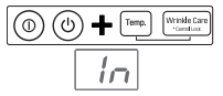
2 Press and hold the POWER, Temp., and Signal buttons until  and a usage count alternate in the display. (The usage count indicates the number of cycles run with no load during the last cycles.)
3 Press the START/PAUSE button.
The dryer will start the test, which will last about minutes. The heat will be turned on and the temperatures in the drum will be measured and displayed. A chime sounds when the test portion of the cycle is complete.

4 Check the display for results.
Check the display for results. During the test cycle, monitor the Flow Sense™ display on the control panel. If the Flow Sense™ LED is not turned on, when the cycle ends, the exhaust system is adequate. If the exhaust system is severely restricted, the Flow Sense™ LED will be turned on. Other problems may also be shown with error codes. See the chart below for error code details and solutions.
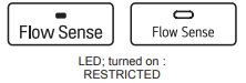
The Flow Sense™ LED indicates that the exhaust system is severely restricted. Have the system checked immediately, as performance will be poor
5 End of cycle.
At the end of the test cycle, will display. The test cycle will end and the dryer will shut off automatically after a short delay.

- Check the error code before you call for service

If the Flow SenseTM LED is turned on, check the exhaust system for restrictions and damage. Repair or replace the exhaust system as needed.
NOTE
When the dryer is first installed, this test should be performed to alert you to any existing problems with the exhaust duct in your home.
However, since the test performed during normal operation provides more accurate information on the condition of the exhaust duct than does the installation test, the number of bars displayed during the two tests may not be the same.
Do not interrupt the test cycle, as this could result in inaccurate results.
Even if no bars are displayed during the test cycle, some restrictions may still be present in the exhaust system. Refer to the Venting the Dryer section of this manual for complete exhaust system and venting requirements.
Restricted or Blocked Airflow
Avoid long runs or runs with multiple elbows or bends.

Check for blockages and lint buildup.

Make sure the ductwork is not crushed or restricted.

OPERATION
Using the Dryer
1 Clean the Lint Filter
If the lint filter has not already been cleaned, lift out the filter and remove the lint from the last load. This will help ensure the fastest and most efficient drying perfor�mance. Make sure to reinstall the filter, pressing down until it clicks firmly into place.The dryer will not operate without the lint filter in place.

2 Load the Dryer
Load the dryer with the wet laundry from the washer. If the load is extra large, you may need to divide it into smaller loads for proper performance and fabric care.

3 Turn on The Dryer
Press the POWER button to turn ON the dryer. The cycle LEDs will illuminate and a chime will sound.

4 Select a Cycle
Turn the cycle selector knob in either direction until the LED for the desired cycle is on. The preset temperature, dry level, and option settings for that cycle will be shown. Default settings for the selected cycle can now be changed if desired. Refer to the Cycle Setting and Options page for details.
NOTE: Not all options or modifiers are available on all cycles. A different chime will sound and the LED will not come on if the selection is not allowed.

5 Begin the Cycle
Press the START/PAUSE button to begin the cycle. The cycle can be paused at any time either by opening the door or by pressing the START/PAUSE button.
If the cycle is not restarted within 60 minutes of being paused, the dryer will shut off and the settings will be lost.

6 End of Cycle
When the cycle is finished, the chime will sound. Immediately remove your clothing from the dryer to reduce wrinkling. If Wrinkle Care is selected, the dryer will tumble briefly every few minutes to help prevent wrinkles from setting in the clothes.

Check the Lint Filter Before Every Load
Always make sure the lint filter is clean before starting a new load; a clogged lint filter will increase drying time. To clean, pull the lint filter straight up and roll any lint off the filter with your fingers. Do not rinse or wash the filter to remove lint. Push the lint filter firmly back into place. See Regular Cleaning for more information.
Always ensure the lint filter is properly installed before running the dryer. Running the dryer with a loose or missing lint filter will damage the dryer and articles in the dryer.

Sorting Loads
Fabric Care Labels
Most articles of clothing feature fabric care labels that include instructions for proper care.

Group Similar Items
For best results, sort clothes into loads that can be dried with the same drying cycle.
Different fabrics have different care requirements, and some fabrics will dry more quickly than others. For best fabric care results, always dry fabrics with similar care requirements together.
Loading the Dryer
Warning: To reduce the risk of fire, electric shock, or injury to persons when using this appliance, follow basic precautions, including the following:
- Check all pockets to make sure that they are empty. Items such as clips, pens, coins, and keys can damage both your dryer and your clothes. Flammable objects such as lighters or matches could ignite, causing a fire. Failure to do so may result in fire, explosion, or death.
- Never dry clothes that have been exposed to oil, gasoline, or other flammable substances. Washing clothes will not completely remove oil residues. Failure to obey this warning may result in fire, explosion, or death.
Loading Tips
- Combine large and small items in the same load.
- Damp clothes will expand as they dry. Do not overload the dryer; clothes require room to tumble and dry properly.
- Close zippers, hooks, and drawstrings to prevent these items from snagging or tangling on other clothes.
Control Panel
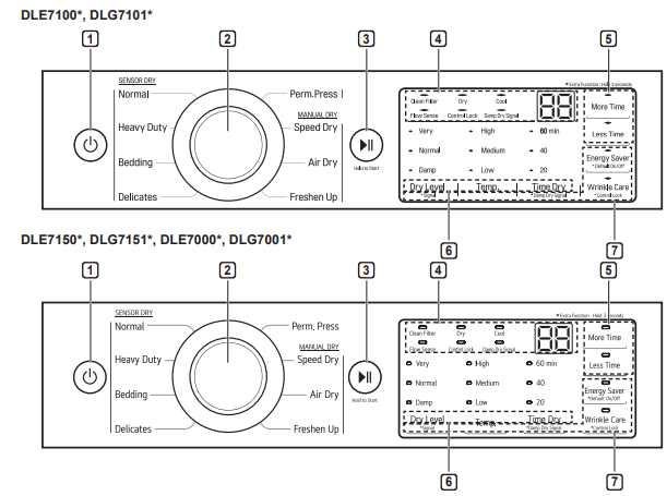
1 POWER Button Press to turn the dryer ON. Press again to turn the dryer OFF.
2 Cycle Selector Knob Turn this knob to select the desired cycle. Once the desired cycle has been selected, the standard presets are shown in the display. On Manual Dry cycles, these settings can be adjusted using the cycle modifier buttons any time before starting the cycle.
3 START/PAUSE Button Press this button to start the selected cycle. If the dryer is running, use this button to pause the cycle without losing the current settings.
4 Time and Status Display The display shows the settings, estimated time remaining, options, and status messages for the dryer.
5 MORE TIME/LESS TIME Buttons Use these buttons with the Time Dry and other Manual Dry cycles to adjust the drying time. Press the MORE TIME button to increase the selected manual cycle time by 1 minute; press the LESS TIME button to decrease the cycle time by 1 minute.
6 Cycle Modifier Buttons Use these buttons to select the desired cycle settings for the selected cycle. The current settings are shown in the display. Press the button for that modifier to select other settings.
7 Cycle Option Buttons The option buttons allow you to select additional cycle options. Certain buttons also allow you to activate special functions by pressing and holding the button for 3 seconds.
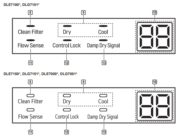
8 Clean Filter Reminder The display will show Clean Filter when the dryer is turned on as a reminder to check the filter. It turns off when the START/PAUSE button is pressed.
9 Cycle Completion Indicator with Check Filter Reminder This portion of the display shows which stage of the drying cycle is currently underway (Dry, Cool)
10 Estimated Time Remaining This display shows the estimated time remaining for SENSOR DRY cycles or the actual time remaining for Time Dry or MANUAL DRY cycles
11 Flow Sense™ Duct Blockage Sensing System Indicator
The Flow Sense™ duct blockage sensing system detects and alerts you to blockages in the ductwork that reduce exhaust flow from the dryer. Maintaining a clean exhaust system improves operating efficiency and helps minimize service calls, saving you money.
12 Control Lock Indicator When Control Lock is set, the Control Lock indicator appears and all buttons are disabled except the POWER button. This prevents children from changing settings while the dryer is operating.
13 Damp Dry Signal Indicator The dryer will signal when the load is approximately 80% dry. This allows you to remove faster- drying lightweight items or items that you would like to iron or hang while still slightly damp
Cycle Guide


Sensor dry cycles
Sensor dry cycles utilize LG’s unique dual sensor system to detect and compare the moisture level in clothes and in the air and adjust the drying time as needed to ensure superior results. The dryer automatically sets the dryness level and temperature at the recommended setting for each cycle. The estimated time remaining will be shown in the display.
NOTE
To protect your garments not every dryness level, temperature, or option is available with every cycle. See the Cycle Guide for details.
Manual dry cycles
Use manual dry cycles to select a specific amount of drying time and a drying temperature. When a manual dry cycle is selected, the Estimated Time Remainng display shows the actual time remaining in your cycle. You can change the actual time in the cycle by pressing More Time or Less Time.
Cycle Settings and Options
Cycle Modifier Buttons
SENSOR DRY cycles have preset settings that are selected automatically. MANUAL DRY cycles have default settings, but you may also customize the settings using the cycle modifier buttons. Press the button for that option to view and select other settings.
Dry Level
Selects the level of dryness for the cycle. Press the Dry Level button repeatedly to scroll through available settings.
- This option is only available with SENSOR DRY cycles.
- The dryer will automatically adjust the cycle time. Selecting More Dry or Very Dry will increase the cycle time, while Less Dry or Damp Dry will decrease the cycle time.
- Use a Less Dry or Damp Dry setting for items that you wish to iron.
Temp.
Adjusts the temperature setting. This allows precise care of your fabrics and garments. Press the Temp. button repeatedly to scroll through available settings.
Time Dry
Allows you to manually select the drying time, from 20 to 60 minutes, in 10-minute increments. Use this for small loads or to remove wrinkles.
More Time/Less Time
Use the More Time/Less Time buttons to add or reduce the drying time of a MANUAL DRY cycle in minute increments.
Cycle Option Buttons
The dryer features several additional cycle options to customize cycles to meet individual needs. Certain option buttons also feature a special function that can be activated by pressing and holding that option button for 3 seconds. (See Special Functions on the following page for details.)
Adding Cycle Options to a Cycle:
- Turn on the dryer and turn the cycle selector knob to select the desired cycle.
- Use the cycle modifier buttons to adjust the settings for that cycle.
- Press the cycle option button(s) for the option you would like to add. A confirmation message is shown in the display.
- Press the START/PAUSE button to start the cycle. The dryer starts automatically.
Wrinkle Care
Selecting this option will tumble the load periodically for up to 3 hours after the selected cycle, or until the door is opened. This is helpful in preventing wrinkles when you are unable to remove items from the dryer immediately.
Energy Saver (on some models)
This option helps to reduce energy consumption in the Normal cycle, depending on the load size.
When the Energy Saver option is selected, the cycle begins with an air dry section and the drying time is increased.
NOTE
The Energy Saver option is turned on by default in the Normal cycle. Turn off the Energy Saver option for a faster Normal cycle which begins with heated drying.
Special Functions
Some cycle option buttons also activate secondary functions. These special functions are marked with an asterisk (*). Press and hold the option button marked with the special function to activate it.
Control Lock
Use this option to prevent unwanted use of the dryer or to keep cycle settings from being changed while the dryer is operating.
Press and hold the button marked Control Lock for seconds to activate or deactivate the Control Lock function. The Control Lock icon will be shown in the display, and all controls will be disabled except the POWER button.
NOTE
Once set, Control Lock remains active until it is manually deactivated. Control Lock must be turned off to run another cycle. To deactivate Control Lock, press and hold the Control Lock button for 3 seconds.
Damp Dry Signal
With this option, the dryer will signal when the load is approximately 80% dry. This allows you to remove faster- drying lightweight items or items that you would like to iron or hang while still slightly damp.
Default On/Off
This option allows the Energy Saver settings to be changed. To run a Normal cycle without the Energy Saver option, press and hold the Energy Saver button for three seconds. ON or OFF appears in the display.
SIGNAL
Press and hold the Dry Level button for 3 seconds to adjust the volume of the signal. Press and hold the button repeatedly to adjust the volume of the melody. When no signal is heard, the signal is off. The volume settings are ON – OFF. The signal volume can be adjusted at any time as long as the dryer is turned ON.
MAINTENANCE
Regular Cleaning
Warning
To reduce the risk of fire, electric shock, or injury to persons when using this appliance, follow basic precautions, including the following:
- Unplug the dryer before cleaning to avoid the risk of electric shock. Failure to follow this warning may cause serious injury, fire, electric shock, or death.
- Never use harsh chemicals, abrasive cleaners, or solvents to clean the washer. They will damage the finish.
Cleaning the Exterior
Proper care of your dryer can extend its life. The outside of the machine can be cleaned with warm water and a mild, nonabrasive household detergent. Immediately wipe off any spills with a soft, damp cloth.
NOTE
- Do not use methylated spirits, solvents, or similar products.
- Never use steel wool or abrasive cleansers; they can damage the surface.
Cleaning the Interior
Wipe around the door opening and seal with a soft, damp cloth to prevent lint and dust buildup that could damage the door seal.
Clean the window with a soft cloth dampened with warm water and a mild, nonabrasive household detergent, then wipe dry.
The stainless steel drum can be cleaned with a conventional stainless steel cleaner, used according to the manufacturer’s specifications. Never use steel wool or abrasive cleansers; they may scratch or damage the surface.
Cleaning Around and Under the Dryer
Vacuum lint and dust from around the dryer and underneath it regularly. Vent ductwork should be checked for lint buildup and cleaned at least once per year. If any noticeable reduction in airflow or drying performance occurs, immediately check ductwork for obstructions and blockages.
Maintaining Ductwork
Vent ductwork should be checked for lint buildup once per month and cleaned at least once per year. If any noticeable reduction in airflow or drying performance occurs, immediately check ductwork for obstructions and blockages. Contact a qualified technician or service provider.
Cleaning the Lint Filter
Always clean the lint from the filter after every cycle.

To clean, open the dryer door and pull the lint filter straight up. Then:
1 For everyday cleaning, roll any lint off the filter with your fingers, or

2 Vacuum the lint filter.

3 If the lint filter has become very dirty or clogged with fabric softener, wash the lint filter in warm, soapy water and allow it to dry thoroughly before reinstalling.

NOTE
NEVER operate the dryer without the lint filter in place. NEVER operate the dryer with a wet lint filter.
Troubleshooting
FAQs: Frequently Asked Questions
Q: When I press a button, why does my dryer beep and then nothing happens?
A: The Control Lock feature is turned on. To turn off Control Lock, turn the dryer on, then press and hold the button that has *Control Lock on or under it for 3 seconds.
Q: Why does my dryer take so long to dry clothes?
A: Proper airflow is critical to the efficient operation of clothes dryers. A lint filter which is full of lint or clogged with fabric softener sheet residue can reduce the airflow to the point that the time required to dry clothing will be greatly increased. Another factor affecting dry time is your home exhaust system. An exhaust system which is dirty and clogged with lint, or is excessively long, needs to be professionally cleaned or repaired.
Q: Why does my dryer start by itself every few minutes?
A: This is how the Wrinkle Care feature works. The dryer runs briefly every few minutes for up to 3 hours after the cycle finishes. This feature is designed to help prevent wrinkles from setting in when the dryer is not unloaded immediately after the cycle is finished.
User Support Videos
For further assistance, there are videos and tutorials available through the LG.com website.
- On the lg.com/us home page, click on the Support menu tab to bring up the menu selections. Select Video Tutorials.
- Select Appliances and Dryers in the search menu on the new page. Scan this QR code to quickly access the video search page on the LG website.

Before Calling for Service
This dryer is equipped with an automatic error-monitoring system to detect and diagnose problems at an early stage. If the dryer does not function properly or does not function at all, check the following before you call for service.
Operation
The Flow SenseTM indicator remains active after clearing the restriction in the venting.
Possible Cause
- After clearing the restriction, the Flow SenseTM system requires multiple, consecutive cycles to determine that the performance value has improved before the Flow SenseTM indicator is reset.
Solutions
- If the Flow SenseTM indicator remains active for more than five cycles after the restriction has been cleared, call for service.
Dryer will not turn on
Possible Cause
- Power cord is not properly plugged in.
- House fuse is blown, circuit breaker has tripped, or power outage has occurred.
Solutions
- Make sure that the plug is securely plugged into a grounded outlet matching the dryer’s rating plate.
- Reset circuit breaker or replace fuse. Do not increase fuse capacity. If the problem is a circuit overload, have it corrected by a qualified electrician.
Dryer does not heat
Possible Cause
- House fuse is blown, circuit breaker has tripped, or power outage has occurred.
- Gas supply or service is turned off (gas models only).
- Energy Saver option selected on some models)
Solutions
- Reset circuit breaker or replace fuse. Do not increase fuse capacity. If the problem is a circuit overload, have it corrected by a qualified electrician.
- Confirm that the house gas shutoff and the dryer gas shutoff valves are both fully open. Even if gas is not supplied to the dryer, it will run and display error code. Verify that other gas appliances in the home are working normally.
- If using the Cotton/Normal cycle, deselect the energy saver option. The Energy Saver option is selected by default. This option reduces energy use by adding an air dry section to the beginning of the cycle. It is normal to feel no heat at the beginning of the cycle while in Energy Saver mode.
Display show error code nP
Possible Cause
- Electric dryer power cord is not connected correctly, or house power supply is incorrect.
Solutions
- Check the power supply or the connection of the power cord to the terminal block.
Display show error code gAS
Possible Cause
- Gas supply or service turned off gas models only).
Solutions
- Confirm that house gas shutoff and the dryer gas shutoff are both fully open.
Clothes take too long to dry
Possible Cause
- Exhaust ducts are blocked, dirty, or duct run is too long.
- Load is not properly sorted.
Solutions
- Confirm that the exhaust duct is properly configured and free of debris, lint, and obstructions. Make sure that outside wall dampers can open properly and are not blocked, jammed, or damaged.
- Separate heavy items from lightweight items. Larger and heavier items take longer to dry. Light items in a load with heavy items can fool the sensor because the light items dry faster.
Clothes take too long to dry
Possible Cause
- Large load of heavy fabrics.
- Dryer controls are not set properly.
- Lint filter needs to be cleaned.
- House fuse is blown, circuit breaker has tripped, or power outage has occurred.
- Dryer is overloaded.
- Dryer is underloaded.
Solutions
- Heavy fabrics take longer to dry because they tend to retain more moisture. To help reduce and maintain more consistent drying times for large and heavy fabrics, separate these items into smaller loads of a consistent size.
- Use the appropriate control settings for the type of load you are drying. Some loads may require an adjustment of the dry level setting for proper drying.
- Remove the lint from the filter before every load. With the lint removed, hold the filter up to a light to see if it is dirty or clogged. With some loads that produce high amounts of lint, such as new bath towels, it may be necessary to pause the cycle and clean the filter during the cycle.
- Reset circuit breaker or replace fuse. Do not increase fuse capacity. If the problem is a circuit overload, have it corrected by a qualified electrician.
- Divide extra large loads into smaller loads for better drying performance and efficiency.
- If you are drying a very small load, add a few extra items to ensure proper tumbling action. If the load is very small and you are using SENSOR DRY cycles, the electronic control cannot properly sense the dryness of the load and may shut off too soon. Use TIME DRY or add some extra wet clothes to the load.
Clothes take too long to dry
Possible Cause
- Energy Saver option selected on some models)
Solutions
- If using the Cotton/Normal cycle, deselect the Energy Saver option. This option reduces energy use by adding an air dry section to the beginning of the cycle.
Drying time is not consistent
Possible Cause
- Heat settings, load size, or dampness of clothing is not consistent.
Solutions
- The drying time for a load will vary depending on the type of heat used electric, natural gas, or LP gas), the size of the load, the type of fabrics, the wetness of the clothes, and the condition of the exhaust duct and lint filter. Even an unbalanced load in the washer can cause poor spinning, resulting in wetter clothes which will take longer to dry.
Performance
Greasy or dirty spots on clothes
Possible Cause
- Fabric softener used incorrectly.
- Clean and dirty clothes are being dried together.
- Clothes were not properly cleaned or rinsed before being placed in the dryer.
Solutions
- Confirm and follow the instructions provided with your fabric softener.
- Use your dryer to dry only clean items.Soil from dirty clothes can transfer to the clean clothes in the same or later loads.
- Stains on dried clothes could be stains that were not removed during the washing process. Make sure that clothes are being completely cleaned or rinsed according to the instructions for your washer and detergent. Some difficult soils may require pre-treating prior to washing.
Clothes are wrinkled
Possible Cause
- Clothes dried too long (over dried).
- Clothes left in dryer too long after cycle ends.
Solutions
- Over drying a load of laundry can lead to wrinkled clothes. Try a shorter drying time or LESS DRY setting and remove items while they still retain a slight amount of moisture.
- Use the WRINKLE CARE option. This feature will tumble the clothes briefly every few minutes for up to 3 hours to help prevent wrinkling.
Clothes are shrinking
Possible Cause
- Garment care instructions are not being followed.
- Some fabrics will naturally shrink when washed.
Solutions
- To avoid shrinking your clothes, always consult and follow fabric care instructions.
- Other fabrics can be washed but will shrink when dried in a dryer. Use a low or no heat setting.
Lint on clothes
Possible Cause
- Lint filter not cleaned properly.
- Laundry not sorted properly.
Solutions
- Remove the lint from the filter before every load. With the lint removed, hold the filter up to a light to see if it is dirty or clogged. If it looks dirty, follow the cleaning instructions. With some loads that produce high amounts of lint, it may be necessary to clean the filter during the cycle.
- Some fabrics are lint producers (i.e., a fuzzy white cotton towel) and should be dried separately from clothes that are lint trappers (i.e., a pair of black linen pants).
Lint on clothes
Possible Cause
- Excess static in clothes.
- Dryer is overloaded.
- Tissue, paper, etc., left in pockets.
Solutions
- Use a fabric softener to reduce static electricity. Be sure to follow the manufacturer’s instructions. Overdrying a load of laundry can cause a buildup of static electricity. Adjust settings and use a shorter drying time, or use SENSOR DRY cycles.
- Divide extra large loads into smaller loads for drying.
- Check pockets thoroughly before washing and drying clothes.
Excess static in clothes after drying
Possible Cause
- Fabric softener is not used or used incorrectly.
- Clothes dried too long overdried).
- Drying synthetics, permanent press, or synthetic blends.
Solutions
- Use a fabric softener or the STATIC SHIELD option, if equipped, to reduce static electricity. Be sure to follow the manufacturer’s instructions.
- Overdrying a load of laundry can cause a buildup of static electricity. Adjust settings and use a shorter drying time, or use AUTO DRY cycles. Select a LESS DRY setting on SENSOR DRY cycles, if necessary.
- These fabrics are naturally more prone to static buildup. Try using fabric softener, or use LESS DRY and/or shorter TIME DRY time settings.
Clothes have damp spots after a SENSOR DRY cycle.
Possible Cause
- Very large load or very small load.Single large item such as a blanket or comforter.
Solutions
- If items are too tightly packed or too sparse the sensor may have trouble reading the dryness level of the load. Use a Time Dry cycle for very small loads.
Large, bulky items such as blankets or comforters can sometimes wrap themselves into a tight ball of fabric. The outside layers will dry and register on the sensors, while the inner core remains damp. When drying a single bulky item, it may help to pause the cycle once or twice and rearrange the item to unwrap and expose any damp areas.
To dry a few remaining damp items from a very large load or a few damp spots on a large item after a sensor cycle has completed, empty the lint trap, then set a Time Dry cycle to finish drying the item(s).
Error Codes
Error code: tE1 through tE
- Temperature sensor failure.
- Turn off the dryer and call for service.
Display shows error code: PS (electric dryers only)
- Power cord is connected incorrectly.
- Check the connection of the power cord to the terminal block.
Flow SenseTM indicator shows four bars during the drying cycle or the display shows "d80" after drying
- Exhaust system is too long or has too many turns/restrictions.
- Install a shorter or straighter duct run. See the Installation Instructions for details.
- Partial blockage of the ductwork due to lint buildup or other foreign object.
- Ductwork should be checked/cleaned immediately. Dryer can be used in this condition, but drying times will be longer and energy consumption will increase.
This warning light is not a dryer failure and is not covered by the dryer warranty. Contact a duct cleaning service to set up an appointment to have your exhaust system cleaned and inspected.
- The appliance has detected a restriction in the external dryer venting.
- If exhaust restrictions are sensed by the Flow SenseTM system, the indicator will remain on for 2 hours after the end of the cycle. Opening the door or pressing the POWER button will turn off the display.
The Flow SenseTM indicator remains active after clearing the restriction in the venting.
- After clearing the restriction, the Flow SenseTM system requires multiple, consecutive cycles to determine that the performance value has improved before the Flow SenseTM indicator is reset.
- If the Flow SenseTM indicator remains active for more than five cycles after the restriction has been cleared, call for service.
 indicator light is on during the drying cycle
- Lint filter not cleaned properly.
- Remove the lint from the filter before every load. With the lint removed, hold the filter up to a light to see if it is dirty or clogged. If it looks dirty, follow the cleaning instructions. With some loads that produce high amounts of lint, it may be necessary to clean the filter during the cycle.
The display shows d90, d95 
- The duct work is about 90%-95% blocked.(“d90” or “d95” error code is displayed for 2 hours only)
- Do not use the dryer until the exhaust system has been cleaned and/or repaired.
- Using the dryer with a severely restricted exhaust is dangerous and could result in a fire or other property damage.
- House exhaust system blocked.
- Check the outside dryer vent while the dryer is operating to make sure there is strong airflow.
- If the exhaust system is extremely long, have it repaired or rerouted.
- Keep the area around the dryer clean and free of clutter.
- Check vent hood for damage or lint clogging.
- Make sure the area around the vent hood is clear