Loading ...
Loading ...
Loading ...

CB / CB-UL, CBF / CBF-UL (E7) 07/2021 Page 141/197
The interior socket’s voltage is turned off at the chamber controller via operation line (chap. 7.3, 9.7.3,
10.6.5).
Turning off the chamber at the main power switch also switches the interior socket voltage-free.
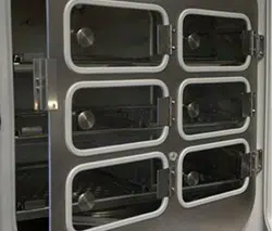
Figure 33: Interior socket (G) (front view) Figure 34: Supplied plug (front view)
Electrical data socket and plug: IP system of protection 65, 230 V 1N ~ 50-60 Hz
NOTICE
Risk of short circuit caused by penetration of moisture into the socket.
Damage to the chamber.
Use the supplied plug only (IP protection type 65).
If the socket is not used, close it with the waterproof lid.
When inserting a heat load into the inner chamber by introducing electrical devices such as shakers or
rollers, the ambient temperature of the incubator must not exceed 25 °C / 77 °F. Otherwise, temperature
control to 37 °C / 98.6°F cannot be assured. When operating electrical devices inside the incubator, always
check the desired incubation temperature before introducing any cells.
NOTICE
Danger of excessive inner temperature > 37 °C / 98.6 °F when operating electrical
devices inside the incubator.
Damage to the cell cultures.
Make sure that the ambient temperature is ≤ 25 °C / 77 °F w
hen operating electrical
devices inside the incubator:.
Check the temperature observation before introducing any cells.
18.5 Analog outputs for temperature and CO
2
(option)
With this option, the chamber is equipped with analog outputs 4-20 mA for temperature and CO
2
. These
outputs allow transmitting data to external data registration systems or devices.
The connection is realized as a DIN socket (4) on the chamber rear. A suitable DIN plug is enclosed.
ANALOG OUTPUT 4-20 mA DC
PIN 1: Temperature +
PIN 2: Temperature -
PIN 3: CO
2
+
PIN 4: CO
2
-
CO
2
range: 0 vol.-% up to 20 vol.-%
Temperature range: 0 °C / 32°F up to +200 °C / 392°F
Figure 35: Pin configuration of the DIN socket (4) on the chamber rear
Pin 2 (L)
Pin 1 (N)
Pin 3 (PE)
Pin 2 (L)
Pin 1 (N)
Pin 3 (PE)
Loading ...
Loading ...
Loading ...
