Loading ...
Loading ...
Loading ...
5
TCP MODE 3
TCP (TRAFFIC CONTROL MODE WITH PRE-WARNING) MODE 3
This mode is intended to control auxiliary devices connected to relays R1, R2, and R3. It provides dry contact control based on the
position/movement of the door and the Timer-to-Close (TTC) status. It also incorporates an adjustable TTC plus a separately adjustable
Pre-Warning. The relays can be used with or without the timers programmed. This mode would be used in lieu of previous
modification 90-T4.
Fully Open
(OLS)
Timer Stage 1
(OLS & OMS
Only)
Timer Stage 2
(Pre-Warning)
(OLS, OMS, &
USP Only)
Closing
Fully Closed
(CLS)
Opening Undefined
Stopped
Position (USP)
Open Mid-Stop
(OMS)
Reversing from
Obstruction
R1 LED
R2 LED
R3 LED
OFF
ON
OFF
OFF
ON
OFF
ON
OFF
OFF
OFF
OFF
ON
OFF
OFF
OFF
OFF
OFF
ON
OFF
OFF
OFF
OFF
ON
OFF
OFF
OFF
ON
NOTES:
• Relay LEDs R1, R2, and R3 on the TLS1CARD will turn ON at the same time as relays R1, R2, and R3.
• During timer stages 1 and 2 the relays shown are only ON/OFF when the door is positioned as shown in parenthesis. The selector
dial on the operator would be set to T, TS, or FSTS.
After configurations and connections have been made for your card mode proceed to Installation page 10.
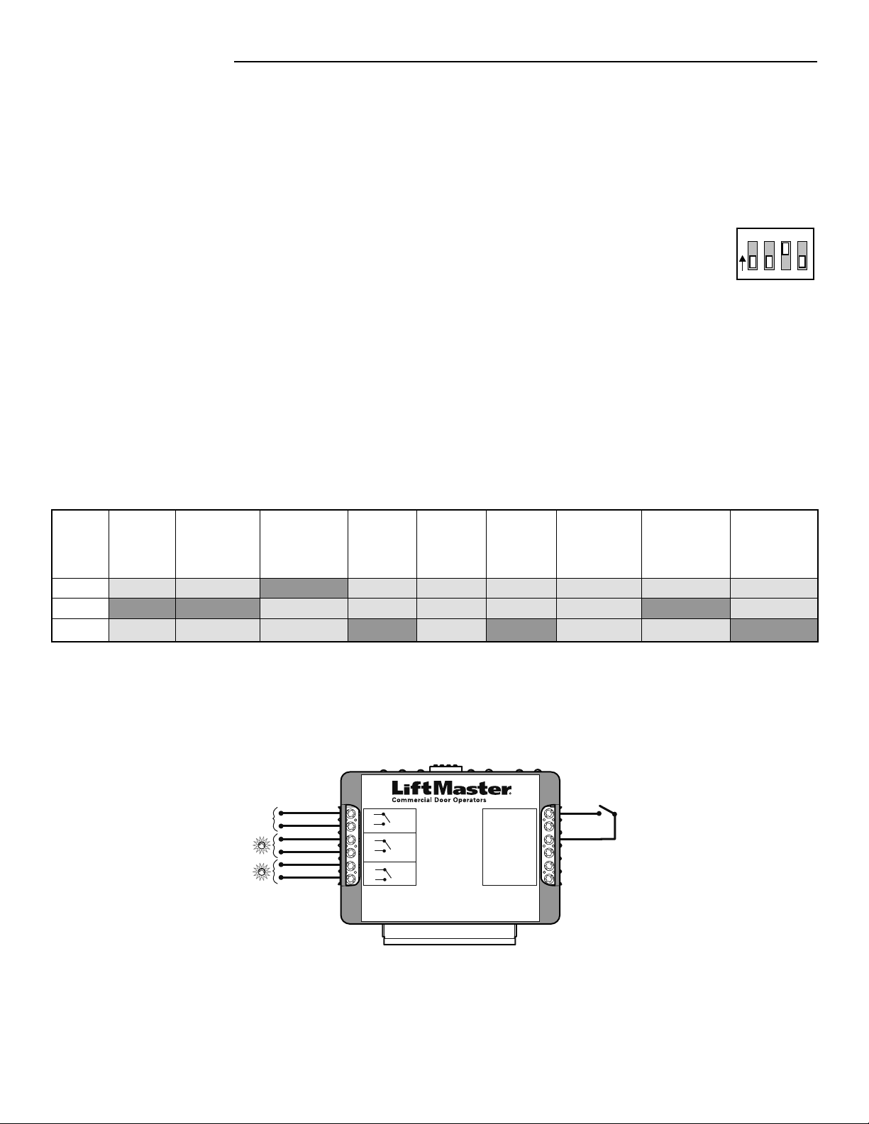
Outputs:
• Connect a red light to the R1 terminals on the TLS1CARD. This will signal the door is about to close.
• Connect a green light to the R2 terminals on the TLS1CARD. This will signal that the door is fully open or at the open mid-stop
position.
• Connect an audio/visual signalling device to the R3 terminals on the TLS1CARD. This will signal that the door is in motion.
Inputs:
• If the application warrants the use of Timer Secure mode at some times and Timer modes at other times, set the operator selector
dial to TS and make a connection to the T/TS input. The input should have a latched contact, such as a 2-position maintained
keyswitch to switch between TS and T.
Disconnect power to the operator.
Turn DIP switch 3 on the TLS1CARD to the ON position. All other DIP switches should remain OFF.
Connect the auxiliary device(s) to the input and output terminals on the TLS1CARD as described below.
1
2
3
1
234
O
N
TCP MODE 3 DIP SWITCH SETTINGS
TLS1CARD
40-35757-1
Timer Light Status Option Card
R3
R2
R1
6
5
4
3
2
1
T/TS 12
FD/SIS 11
COMMON 10
SIC 9
SIO 8
COMMON 7
(RELAYS)
OUTPUTS
INPUTS
5 A, 230 Vac, 30 Vdc Dry Contact Only
N.O.
Comm
N.O.
Comm
N.O.
Comm
Horn/Strobe
Green
Red
TCP MODE 3 (TYPICAL CONNECTION)
2-Position
Maintained Switch
Loading ...
Loading ...
Loading ...