Loading ...
Loading ...
Loading ...
Product Assembly
d. Attach the Front
Rotator Cuff (63) & Back
Rotator Cuff (64) to the
Right Handlebar (67) and
fully tighten with 4pcs
Phillips Pan Screws (M5
x p0.8 x 15mm) (147).
STEP 7 – (Continued) Upper Handlebar (66, 67) & Rotator Cuff (63, 64) Assembly.
STEP 8 – OVERVIEW Stationary Handrail (74, 75) & Rear Support Tube (102, 103)
Assembly
Overview image for
STEP 8a thu STEP 8i
e. Repeat STEP 7d for Left
....Side.
PHILLIPS SCREWDRIVERS #2
w/ Magnetic TIP
PHILLIPS SCREWDRIVERS #2
w/ Magnetic TIP
Recommended Tool:
15
Product Assembly
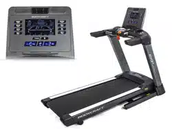
Only loosely tighten ALL BOLTS until STEP 8
STEP 3 – Install Upright Post - Left
a. Attach the Upright Post - Left (063) to
the Base Assembly (001-ASM) using
the following hardware:
i. Four Allen Head Bolts,
M8 x 20mm L (072)
WRENCH 13mm
Recommended Tools:
ALLEN WRENCH 6mm)
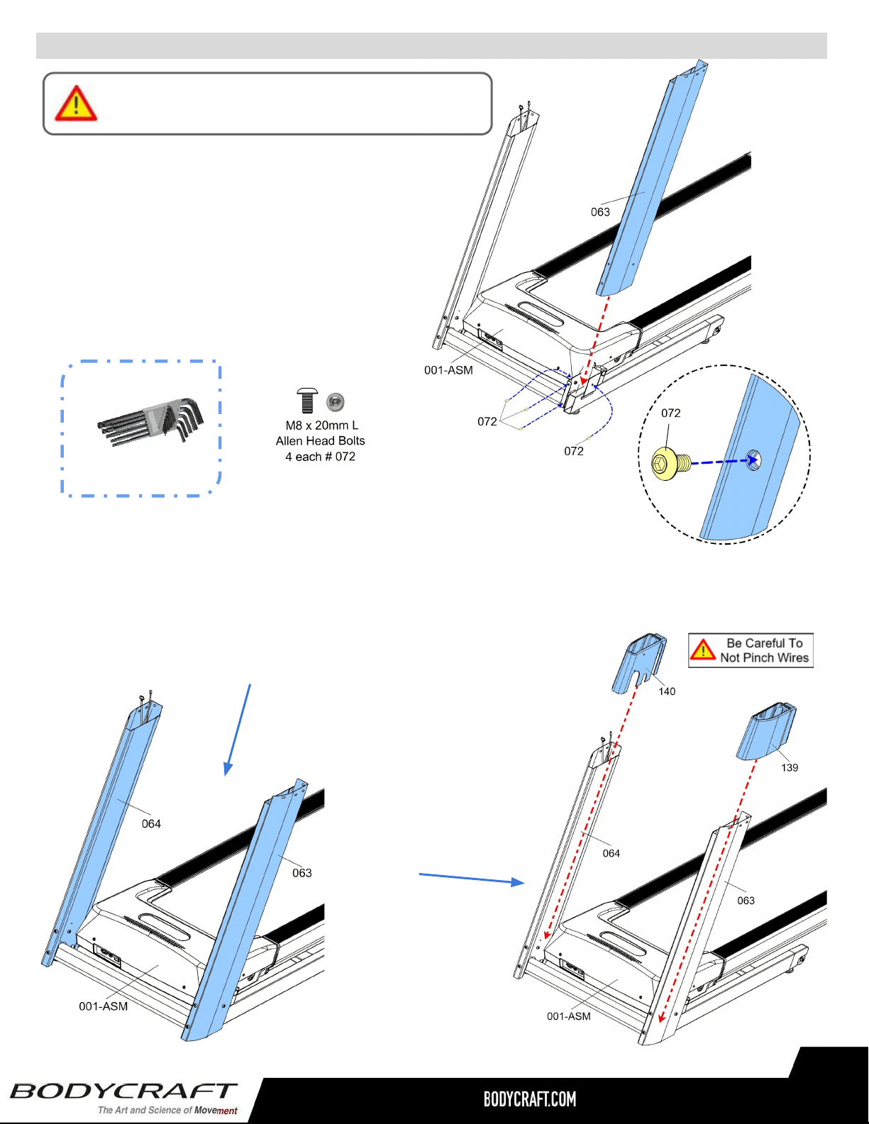
a. Confirm the two Cables are hanging out of the top of Upright Post - Right (064).
b. Confirm both Upright Posts - Left (063) and Right (064) have movement
and the bolts ARE NOT fully tightened.
NOTE: Needed for STEP 5 - STEP 8 assembly
STEP 4 – Prepare for the Dashboard Assembly
c. Then slide on both
Upright Post Covers -
Lower - Left (139) and
Right (140). As shown
on CAD image to the
right.
15
ALLEN WRENCH
6mm
Recommended Tool:
Loading ...
Loading ...
Loading ...