
Loading ...
Loading ...
Loading ...
Product Assembly
Many Images shown are GENERIC for both the EXP Series
Treadmills T1000 / T800 / T400 on most assembly STEPS
13
13
Fig. 1
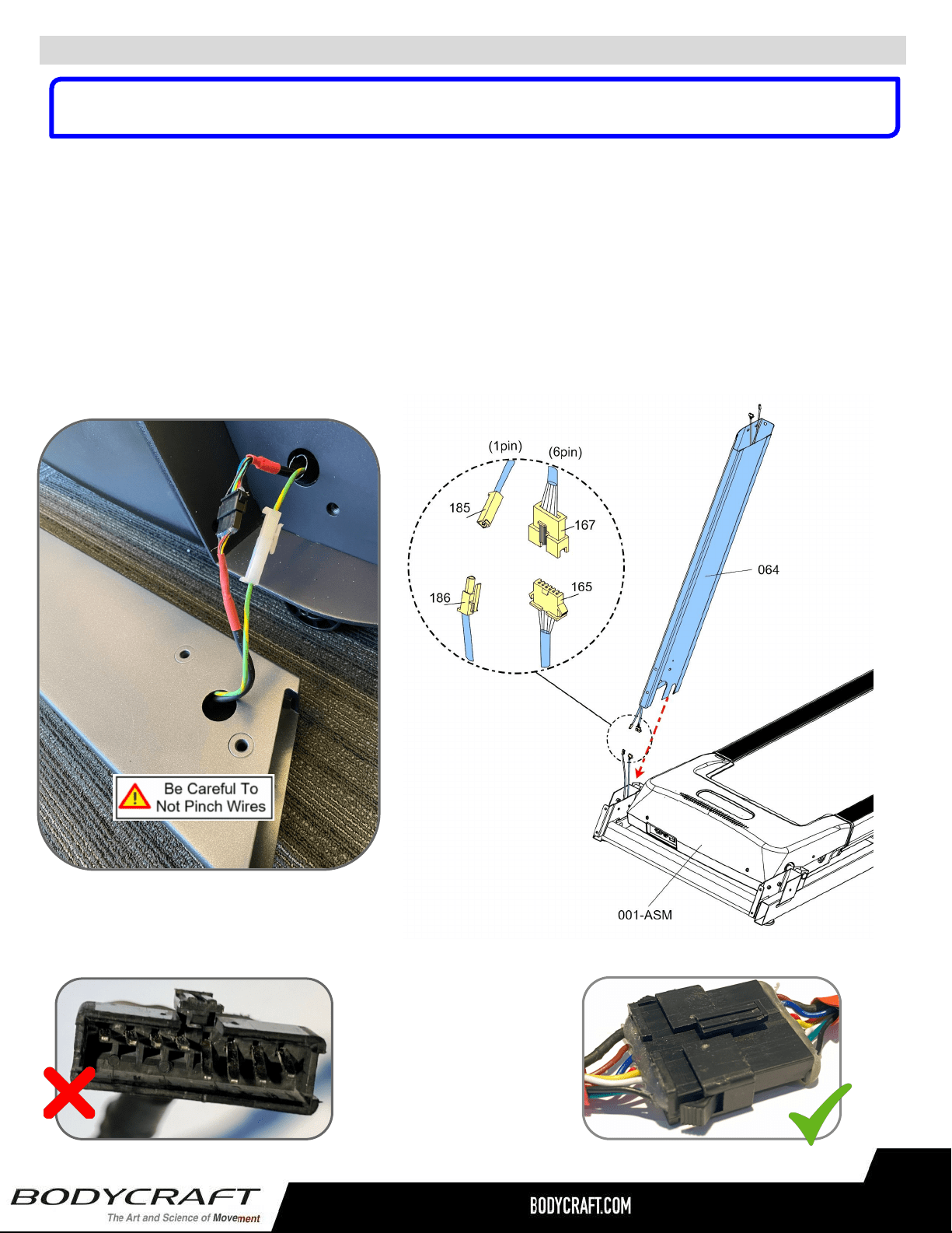
STEP 1 – Upright Post-Right Wiring Connection
Fig. 3
Fig. 2
a. Lay the Upright Post-Right (064) next to the treadmill’s Base Assembly (001-ASM) on
its right side. See example pic. on (Fig. 1)
b. Then connect the following cables from the Upright Tube - Right (064) to the Base
Assembly (001-ASM):
i. Cable - Mid (#167 w/6pin) <<<< --- >>> Cable - Lower (#165 w/6pin)
ii. Grounding Cable (#185 w/1pin) <<< --- >>> Grounding Cable (#186 w/1pin)
NOTE: Confirm connections have no bent pins (Fig. 2) and are securely locked (Fig. 3) with a gentle
pull after connected.
NOTE: Many images shown are GENERIC for the EXP Series Treadmills T1000 / T800 / T400 on
multiple assembly STEPS.
Loading ...
Loading ...
Loading ...