Loading ...
Loading ...
Loading ...

WATERMAZE SERIES OPERATOR’S MANUAL
7
WB • 8.913-984.0-N
WARNING: The gas line must be
installed by qualified person-
nel only. It must be checked for
leaks before installing the WATER
MAZE. All gas piping must com-
ply with local and national fuel
gas codes.
Connect the main gas line to the 1"
or 1-1/2" line on the rear panel of the
WATER MAZE. This will be labeled
“Natural Gas Only” or “L.P. Gas Only” depending on the
machine you purchase. Connect the vent line to the 1"
vent pipe on the rear panel of the WATER MAZE (see
figures 1-3).
CAUTION: This vent pipe must be vented to the at-
mosphere.
Electrical:
The WATER MAZE requires 230 volts single phase. Re-
fer to the serial plate for proper voltage and amp require-
ments for your machine. All electrical lines must be tested
with a voltage meter for proper voltage before connect-
ing to the WATER MAZE. NOTE: If 208V single phase
is the only electrical source available, the step down
transformer must be changed to a 208/120V transformer
(#6-60011) or a buck boost transformer must be used
to increase the voltage.
DANGER: All electrical lines must
be installed by qualified person-
nel only. All installations must
be electrically grounded and
conform to all local and national
electrical codes. Water Maze is
ETL listed.
The electrical connection for the
WATER MAZE is located on the
rear panel conduit box using a 1/2" knock-out. Electrical
conduit must be run all the way to the connection point
in accordance with local codes.
Fresh Water:
During initial start up, we recommend using fresh water in
the wastewater tank. Fill to mark indicated on sight tube
and remove garden hose. Connect the garden hose to the
WATER MAZE at the female connector located on the 3
point level controller. Open valve partially so back pres-
sure doesn't fill up sight glass tube.
Wastewater:
Wastewater is drawn directly into the evaporator using
the air pump supplied. A 20 mesh stainless steel filter
protects the pump from debris. The connection between
the above ground waste water tank and the machine is
made by using a 3/4" I.D. supply hose with common
WARNING
GAS LINE MUST
BE INSTALLED BY
QUALIFIED
PERSONNEL ONLY.
Control Rod:
Automatic wastewater control set points on the 3 Point
Level Controller turns the wastewater air pump on and
off to control the water level inside the evaporator. The
controller also shuts burner off if water level gets to low.
Temperature Control:
Dual, manual reset, and high temperature controls
monitor the internal temperature of the evaporator. If the
exhaust or water temperatures become too high (225°F)
the system shuts down. The temperature is usually in
the 180° to 190° range.
Regulator Venting:
A pressure regulator gas vent is provided. The gas vent
needs to be plumbed to the atmosphere. If the gas
regulator fails, the gas is automatically vented out-
side, preventing a gas buildup in the location of the
WATER MAZE. This must be vented to comply with
local and/or national codes.
Demister Box:
The demister box contains screens inside that prevent
large water droplets from going up the stack (screen
hole size is 3/16").
INSTALLATION
Location:
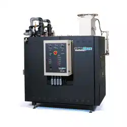
Locate the WATER MAZE evaporator on a level con-
crete surface in a room that is well ventilated. Protect the
machine from damaging environment such as wind, rain
and freezing temperatures. Leveling feet are provided
with all evaporators.
CAUTION: For natural gas, air ventilation should
be located near the ceiling. For liquid propane, air
ventilation should be located near the floor.
Gas:
The WATER MAZE evaporator is available for operation
in natural gas or liquid propane.
CAUTION: There are major differences in the adjust-
ments of the evaporators. Do not try to operate the
machine using the wrong gas.
The one inch (1") gas supply line on the WB-25, and
WB-50 and (one and one half inch (1-1/2") on the
WB-120) must have a minimum of 2 psig and a maxi-
mum of 10 psig and be of adequate size to supply the
necessary volume for proper burner operation. The high/
low gas switches require between 12-60 water column
inches. There must be a main gas shut-off valve (not pro-
vided) in the gas supply line located next to the WATER
MAZE which can be used as an emergency shut off for
repair or maintenance purposes.
HAZARDOUS
VOLTAGE. CAN
SHOCK, BURN OR
CAUSE DEATH.
DANGER
Loading ...
Loading ...
Loading ...
