OPERATOR’S MANUAL
For technical assistance or the Water Maze Dealer nearest you consult our web page at
www.wmaze.com
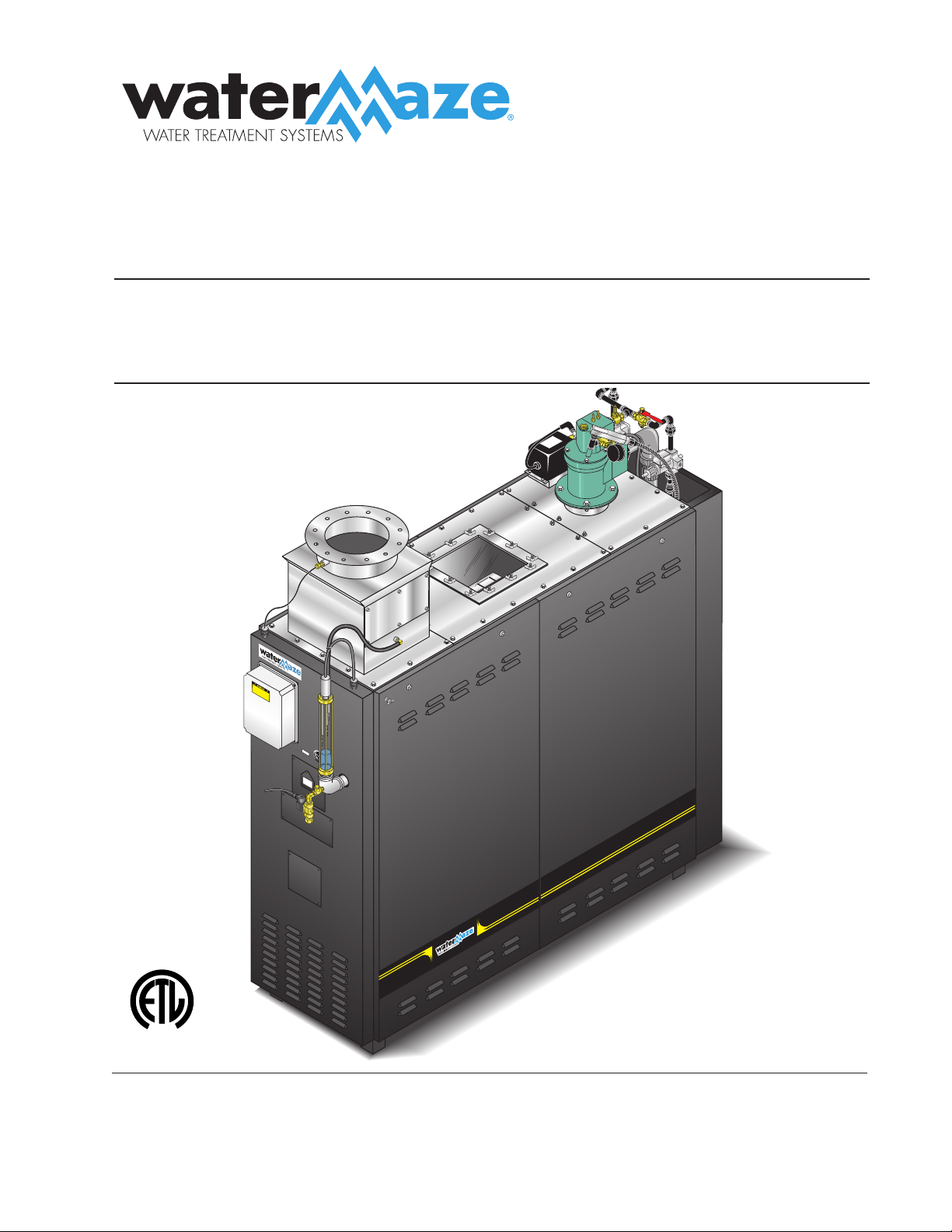
■ WB-50A ■ WB-120A
1.103-474.0 1.103-473.0
WB
L
I
S
T
E
D
®
10/03/19 8.913-984.0-N

WB • #8.913-984.0-N
Introduction .................................................................................................................................... 4
Unpacking ...................................................................................................................................... 4
General Safety Instructions ....................................................................................................... 4, 5
Electrical Safety Information .......................................................................................................... 5
Wiring ........................................................................................................................................ 5, 6
Pump Safety .................................................................................................................................. 6
Standard Safety Features .......................................................................................................... 6, 7
Installation.................................................................................................................................. 7, 8
Pre-Startup Check List .................................................................................................................. 8
Operating Procedure ..................................................................................................................... 9
Principles of Operation .................................................................................................................. 9
Installation Drawings .............................................................................................................10 - 11
Storage Tank Configuration ......................................................................................................... 12
Exhaust Stacking Configuration ................................................................................................... 13
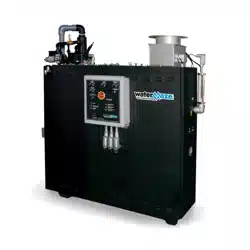
WB-50A Front View ...................................................................................................................... 14
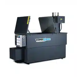
WB-120A Front View .................................................................................................................... 15
Start-Up Procedures .................................................................................................................... 16
Shut Down Procedures ................................................................................................................ 16
Setting the Burner ........................................................................................................................ 17
Soft Start Ignition ......................................................................................................................... 17
Burner Adjustment Diagram ........................................................................................................ 18
Foaming ....................................................................................................................................... 19
Converting Natural Gas to L.P. Gas ............................................................................................. 19
Veri-Flame #7-8061 ..................................................................................................................... 20
3 Point Sensor Control ................................................................................................................. 20
Setting High Limit Control ............................................................................................................ 21
Maintenance ...........................................................................................................................21-23
CONTENTS

Model Number ______________________________
Serial Number ______________________________
Date of Purchase ____________________________
The model and serial numbers will be found on a decal attached
to the evaporator. You should record both serial number and date
of purchase and keep in a safe place for future reference.
CONTENTS
3
WB • 8.913-984.0-N
Programming of Water Maze Cycle Timer ..............................................................................24-26
Water Level Control Unit & Parts List .......................................................................................... 27
WB-50A Exploded View ..........................................................................................................28-29
WB-50A Exploded View Parts List ..........................................................................................30-32
WB Control Panel w/Parts list ................................................................................................. 33-35
WB-120A Exploded View ........................................................................................................36-37
WB-120A Exploded View Parts List ........................................................................................38-40
Water Maze w/Anti-Foam Metering Pump .................................................................................. 41
Air Line Assembly Exploded View and Parts List ...................................................................42-43
Gas Train Assembly WB-50 Exploded View and Parts List .....................................................44-45
Gas Train Assembly WB-120 Exploded View and Parts List ...................................................46-47
Replacing Pump Head Tubing .................................................................................................... 48
Metering Pump and Parts List ..................................................................................................... 49
Peristaltic Metering Pump ............................................................................................................ 48
WB-50/120 Regenerative Blower #5-1503 .................................................................................. 49
Troubleshooting ......................................................................................................................52-54
Specifications ............................................................................................................................... 55
Service Log .................................................................................................................................. 56
Warranty ...................................................................................................................................... 57
4
WATERMAZE SERIES OPERATOR’S MANUAL
WB • 8.913-984.0-N
INTRODUCTION
Your owner's manual has been prepared to provide
you with a simple and understandable guide for equip-
ment operations and maintenance based on the latest
product information available at the time of printing. To
keep your machine in top running condition, follow the
specific maintenance and trouble shooting procedures
given in this manual.
NOTE: WATER MAZE reserves the right to make chang-
es at any time without incurring any obligations
UNPACKING
1. WATER MAZE module with removable doors
2. 20 mesh filter screen in a plastic housing
3. Tube of caulk
4. Operator's manual
5. WATER MAZE tool kit and door removal tool
6. WATER MAZE 5600 Defoamer
7. Bulk head fitting and strain relief
NOTE: Report any damage to machine or components
for claim against the freight line.
Owner/User Responsibility:
The owner and/or user must have an understanding
of the manufacturer’s operating instructions and warn-
ings before using this WATER MAZE machine. Warning
information should be emphasized and understood. If
the operator is not fluent in English, the manufacturer’s
instructions and warnings shall be read to and discussed
with the operator in the operator’s native language by
the purchaser/owner, making sure that the operator
comprehends its contents.
Owner and/or user must study and maintain for future
reference the manufacturers’ instructions.
SAVE THESE INSTRUCTIONS
This manual should be considered a permanent
part of the machine and should remain with it if
machine is resold.
When ordering parts, please specify model and se-
rial number. Use only identical replacement parts.
This machine is to be used only by trained opera-
tors.
PLEASE NOTE: WATER MAZE is not responsible for
procurement of regulatory and/or operating permits that
may be required by city, county, state or federal agen-
cies. It is the customer who is responsible for procure-
ment of any hazardous or non-hazardous regulatory
and/or operating permits, compliance with codes or
other governmental requirements associated with the
installation, use, or disposal of waste associated with this
equipment. Submerged combustion can be classified as
incineration in specific jurisdictions. It is the customer's
responsibility for procurement of appropriate local and
state permits as needed.
The guidelines listed in the evaporator feasibility report
are specific only to the waste stream submitted for evalu-
ation and estimated emissions. Moreover, WATER MAZE
is not reponsible for the operation or maintenance of
the evaporator unit. If the unit is subjected to any waste
stream other than that which has been tested by the
named laboratory, operation may cause adverse effects
on the equipment and will negate any warranty of parts
or equipment.
IMPORTANT SAFETY
INSTRUCTIONS
WARNING: To reduce the risk of
injury, read operating instruc-
tions carefully before using.
1. Read the owner's manual
thoroughly. Failure to follow
the instructions could cause a
malfunction of the machine and
result in death, serious injury
and/or property damage.
2. The installation of the gas line must be done by a
licensed gas contractor and in accordance with local
and/or national codes.
DANGER: The machine, when
installed, must be electrically
grounded in accordance with lo-
cal and/or national codes. Do not
spray water near electrical com-
ponents. Do not touch machine
with wet hands or while standing
in water.
3. Never make adjustments on ma-
chine while it is in operation except those prescribed
in this manual.
4. Do not allow high concentrations of flammable fluids,
acids, caustic or abrasive fluids to pass through the
waste water pump into the combustion chamber.
5. Before servicing this machine, refer to all the MSDS
on the material identified in the waste stream. You
must comply with all warnings and
wear all protective clothing stated
on the MSDS.
WARNING: Avoid installing ma-
chines in small confined areas.
Adequate oxygen is needed for
combustion or dangerous carbon
monoxide will result.
WARNING
READ OPERATOR’S
MANUAL
THOROUGHLY
PRIOR TO USE.
WARNING
DANGEROUS FUMES:
INSTALL ONLY IN
WELL VENTILATED
AREA .
HAZARDOUS
VOLTAGE. CAN
SHOCK, BURN OR
CAUSE DEATH.
DANGER
WATERMAZE SERIES OPERATOR’S MANUAL
5
WB • 8.913-984.0-N
6. Protect inlet hoses from traffic and sharp objects.
7. Be certain hoses and piping have been connected
before operating.
8. Turn the machine off before disconnecting hoses.
9. Inlet influent temperature must not exceed 150°F
(66°C).
10. When making repairs, disconnect the machine from
the electrical source.
11. The best insurance against an accident is precaution
and knowledge of the equipment.
12. WATER MAZE is not liable for any modifications or
the use of components not purchased from WATER
MAZE.
13. The WATER MAZE and components will freeze if
not in operation and must be located in a heated
enclosure in cold climates.
14. Running the system or the pump without water will
damage the pump and will void the warranty.
15. WATER MAZE should be installed and started up
by an authorized WATER MAZE dealer.
16. This machine can be used with natural gas or
propane. A conversion kit can be supplied by the
manufacturer to convert the machine to the alternate
fuel.
WARNING: If you smell gas, shut
off the gas supply valve, extin-
guish any open flame and test all
joints with a soap solution. If the
odor persists, call your gas sup-
plier immediately.
WARNING: Do not locate the ma-
chine in the vicinity of any flam-
mable vapors, liquids or solids.
17. Only those liquid wastes that have been approved by
WATER MAZE and the proper regulatory agencies
should be placed in the WATER MAZE machine.
EPA test methods 8260 and 200.7 must be obtained.
NOTE: If any other liquids that have not been tested
are introduced into the WATER MAZE machine, the
warranty will be void.
18. WARNING: Do not attempt to evaporate flam-
mable wastes of any kind, i.e., do not process
solvents, pure oils, etc.
19. WATER MAZE requires a representative sample
of the waste stream analyzed for pH, metals, total
solids, total suspended solids, oil and grease, foam
and chlorides test.
20. High levels of chlorides and fluorides will cause cor-
rosion especially when heated.
ELECTRICAL SAFETY
INFORMATION
WARNING: To reduce the risk of
injury, read electrical instructions
carefully before using.
WARNING: Do not bypass any
safety feature. You can cause
fires and explosions. Obey the
safety precautions in safety
instructions.
DANGER: Hazardous voltage
can shock, burn or cause death.
Ground machine before connect-
ing to power supply.
1. Ground the equipment before
connecting it to an electrical
power supply.
2. Failure to ground the equip-
ment can cause a severe or
fatal electrical shock hazard.
3. Do not ground to a gas supply line.
4. To avoid dangerous or fatal electrical shock, turn
OFF the power to the equipment before working on
the electrical connections.
5. Supply voltage must be within ± 10% of the name-
plate voltage. Incorrect voltage can cause a fire
or seriously damage the equipment and voids the
warranty. If in doubt, consult a licensed electrician.
6. Connect the equipment to a dedicated circuit with
no other equipment on it.
WIRING
1. Install a ground wire and maintain this equipment
in accordance with your local electrical code and all
other codes and ordinances that apply. Consult your
local building inspector for local code information.
2. Ground the equipment permanently using a wire
of size and type specified by local and/or National
Electrical Code.
3. Connect the ground wire first to the green ground-
ing wire provided. Do not connect the equipment
to an electrical power supply until the machine is
permanently grounded, otherwise serious or fatal
electrical shock hazard may be caused.
4.
For the best ground connection, connect to a ground-
ed lead in the service panel or to a metal underground
water pipe or well casing at least 10 feet long. If plastic
pipe or insulated fittings are used, run the ground
wire directly to the metal well casing or use ground
electrode furnished by the power company.
WARNING
RISK OF FIRE OR
EXPLOSION:
OBEY SAFETY IN-
STRUCTIONS.
WARNING
RISK OF FIRE OR
EXPLOSION:
AVOID FLAMMABLE
LIQUIDS, VAPORS
OR SOLIDS.
HAZARDOUS
VOLTAGE. CAN
SHOCK, BURN OR
CAUSE DEATH.
DANGER
6
WATERMAZE SERIES OPERATOR’S MANUAL
WB • 8.913-984.0-N
5.
If 208V single phase is the only available electrical
source, the step down transformer must be changed to
a 208/120V .500KVA transformer or a buck boost trans-
former must be installed to raise the voltage to 230V.
PUMP SAFETY
WARNING: Do not pump high
concentrations of flammable
liquids or explosives such as
gasoline, fuel oil, kerosene, etc.
Do not use in explosive atmo-
spheres. The Water Maze should
only be used with liquids compat-
ible with Water Maze component
materials. Failure to follow this
warning could result in personal injury and/or prop-
erty damage.
1. Know the pump application, limitations and potential
hazards.
2. Make certain that the power source conforms to the
requirements of your machine; 230V single phase
for all WATER MAZE machines. Always check the
serial plate for power requirements.
3. Release all pressure within the system before servic-
ing any component.
4. Drain all liquids from the components before
servicing.
5. Check hoses for weak or worn condition before each
use, making certain all connections are secure.
6. Periodically inspect sparger tube, nozzle, filter and
other system components. Perform routine mainte-
nance as required.
Personal Safety:
a. Keep work area clean, uncluttered and properly
lit. Replace all unused tools and equipment.
b. Keep visitors at a safe distance from the work
area.
c. Make the workshop safe with padlocks, master
switches and power lock out devices.
7. All wiring and electrical connections must be per-
formed by a qualified electrician.
8. Protect the electrical cord by having the electrician
run all electrical wiring through conduit from the
power source to the machine.
9. Use wire of adequate size to minimize a voltage drop
at the motor.
10. Disconnect the power before servicing a motor or
other components. If the power disconnect is out-of-
sight, lock it in the open position and tag it to prevent
unexpected application of power.
WARNING
RISK OF FIRE OR
EXPLOSION:
OBEY SAFETY
INSTRUCTIONS.
11. Do not touch an operating motor. Modern motors
are designed to operate at high temperatures.
STANDARD SAFETY FEATURES
The WATER MAZE uses electricity, gas and water to
operate. These can be fatal if not handled properly. For
this reason, the WATER MAZE has been designed with
safety in mind. The following are standard safety features
you will find on all WATER MAZE equipment.
Interlock System:
The WATER MAZE has an interlock system which must
be proven before the burner will ignite. All of these inter-
locks are proven through the Veri-Flame.
1. Pre-Ignition Interlocks:
a. High/low gas pressure switches
These switches insure that there is enough gas
pressure to operate the burner but not excessive
pressure (see page 20).
NOTE: The low pressure switch is set at 12 water
column inches (wci). The high pressure switch
is set at 60 water column inches (wci).
b. Air Pressure Switch
This switch insures there is at least 12 water
column inches of air pressure. NOTE: The High,
Low Gas and Air Pressure Switches have inter-
nal lights. If there is a failure, the light goes out.
See pages 43 & 45.
c. Gas Solenoid Valve
This valve must be closed during pre-ignition
checks. If open, the system will shut down.
NOTE: The WB-50 has three gas solenoid
valves. The WB-120 has six gas solenoid valves
(see pages 43-45).
d. 3 Point Sensor Control:
The evaporation tank must have a minimum
amount of water to prevent damage to internal
parts due to excessive heat. If the water level is
at the bottom rod on the 3 Point Sensor Control,
ignition of the burner is prevented (see item 3
page 27).
2. Post-Ignition Interlock:
UV Scanner
A UV scanner looks for the ignition of the burner.
Once the WATER MAZE has gone through the inter-
locks and the 15 second purge process, the burner
goes through an ignition sequence. If the burner fails
to ignite, the UV scanner shuts down the burner.
Filter:
A 20 mesh screen on the incoming waste water line
prevents solids from entering and damaging the pump.
WATERMAZE SERIES OPERATOR’S MANUAL
7
WB • 8.913-984.0-N
WARNING: The gas line must be
installed by qualified person-
nel only. It must be checked for
leaks before installing the WATER
MAZE. All gas piping must com-
ply with local and national fuel
gas codes.
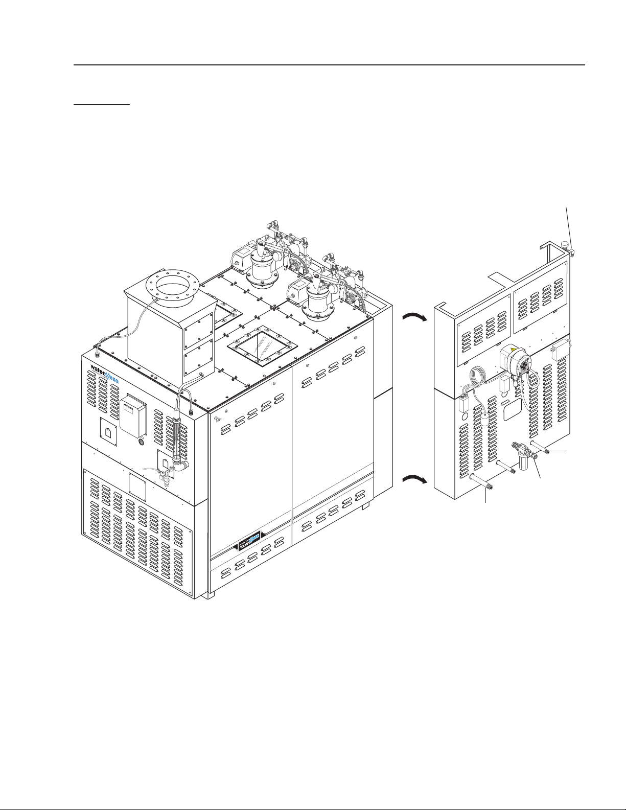
Connect the main gas line to the 1"
or 1-1/2" line on the rear panel of the
WATER MAZE. This will be labeled
“Natural Gas Only” or “L.P. Gas Only” depending on the
machine you purchase. Connect the vent line to the 1"
vent pipe on the rear panel of the WATER MAZE (see
figures 1-3).
CAUTION: This vent pipe must be vented to the at-
mosphere.
Electrical:
The WATER MAZE requires 230 volts single phase. Re-
fer to the serial plate for proper voltage and amp require-
ments for your machine. All electrical lines must be tested
with a voltage meter for proper voltage before connect-
ing to the WATER MAZE. NOTE: If 208V single phase
is the only electrical source available, the step down
transformer must be changed to a 208/120V transformer
(#6-60011) or a buck boost transformer must be used
to increase the voltage.
DANGER: All electrical lines must
be installed by qualified person-
nel only. All installations must
be electrically grounded and
conform to all local and national
electrical codes. Water Maze is
ETL listed.
The electrical connection for the
WATER MAZE is located on the
rear panel conduit box using a 1/2" knock-out. Electrical
conduit must be run all the way to the connection point
in accordance with local codes.
Fresh Water:
During initial start up, we recommend using fresh water in
the wastewater tank. Fill to mark indicated on sight tube
and remove garden hose. Connect the garden hose to the
WATER MAZE at the female connector located on the 3
point level controller. Open valve partially so back pres-
sure doesn't fill up sight glass tube.
Wastewater:
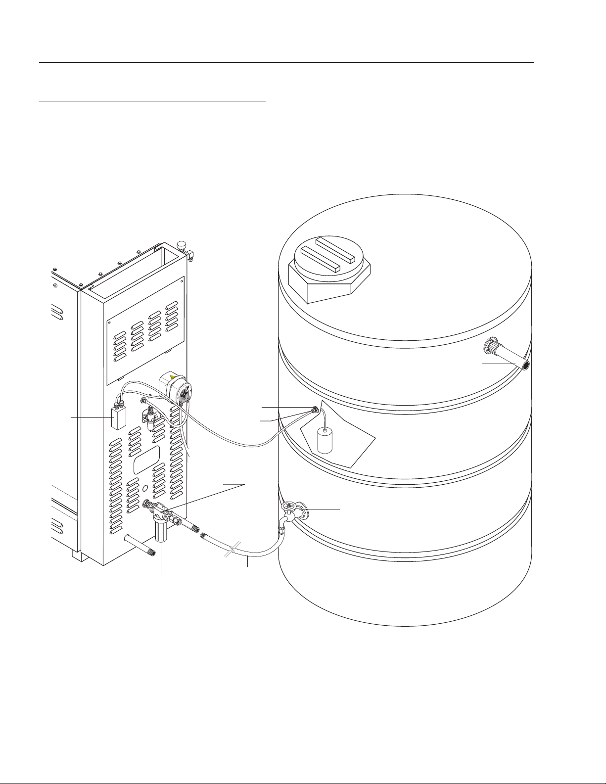
Wastewater is drawn directly into the evaporator using
the air pump supplied. A 20 mesh stainless steel filter
protects the pump from debris. The connection between
the above ground waste water tank and the machine is
made by using a 3/4" I.D. supply hose with common
WARNING
GAS LINE MUST
BE INSTALLED BY
QUALIFIED
PERSONNEL ONLY.
Control Rod:
Automatic wastewater control set points on the 3 Point
Level Controller turns the wastewater air pump on and
off to control the water level inside the evaporator. The
controller also shuts burner off if water level gets to low.
Temperature Control:
Dual, manual reset, and high temperature controls
monitor the internal temperature of the evaporator. If the
exhaust or water temperatures become too high (225°F)
the system shuts down. The temperature is usually in
the 180° to 190° range.
Regulator Venting:
A pressure regulator gas vent is provided. The gas vent
needs to be plumbed to the atmosphere. If the gas
regulator fails, the gas is automatically vented out-
side, preventing a gas buildup in the location of the
WATER MAZE. This must be vented to comply with
local and/or national codes.
Demister Box:
The demister box contains screens inside that prevent
large water droplets from going up the stack (screen
hole size is 3/16").
INSTALLATION
Location:
Locate the WATER MAZE evaporator on a level con-
crete surface in a room that is well ventilated. Protect the
machine from damaging environment such as wind, rain
and freezing temperatures. Leveling feet are provided
with all evaporators.
CAUTION: For natural gas, air ventilation should
be located near the ceiling. For liquid propane, air
ventilation should be located near the floor.
Gas:
The WATER MAZE evaporator is available for operation
in natural gas or liquid propane.
CAUTION: There are major differences in the adjust-
ments of the evaporators. Do not try to operate the
machine using the wrong gas.
The one inch (1") gas supply line on the WB-25, and
WB-50 and (one and one half inch (1-1/2") on the
WB-120) must have a minimum of 2 psig and a maxi-
mum of 10 psig and be of adequate size to supply the
necessary volume for proper burner operation. The high/
low gas switches require between 12-60 water column
inches. There must be a main gas shut-off valve (not pro-
vided) in the gas supply line located next to the WATER
MAZE which can be used as an emergency shut off for
repair or maintenance purposes.
HAZARDOUS
VOLTAGE. CAN
SHOCK, BURN OR
CAUSE DEATH.
DANGER

8
WATERMAZE SERIES OPERATOR’S MANUAL
WB • 8.913-984.0-N
connectors supplied by the customer and is located on
the rear panel with the label, “Wastewater Inlet" (see
page 11). NOTE: The WATER MAZE is automatically
controlled by the 3 point level controller and will supply
wastewater as needed after startup.
CAUTION: Foaming detergents will affect the
evaporation process in the WATER MAZE. An
anti-foaming kit has been installed to control foam.
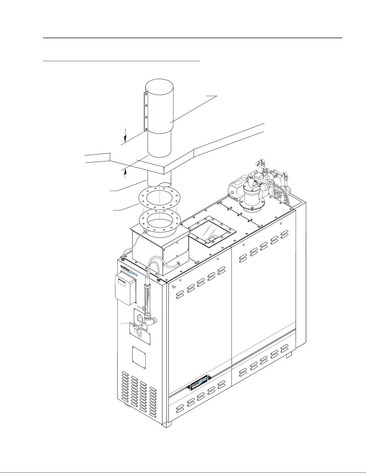
Venting:
Each evaporator must have its own vent stack. A 10"
vent pipe (WB-50) must be installed using the provided
exhaust stack adapter to the machine's exhaust stack
and be vented to the atmosphere. A 12" pipe must
be used for the WB-120 (see figure 4). The top of the
exhaust stack should be sufficiently above the roof to
allow for proper dispersion of the exhaust. It should be
unobstructed and in compliance with all local and federal
codes. Avoid bends if possible.
NOTE: If possible, the stack should be a single piece.
CPVC is the recommended stack material. If it has
seams, the seams must be sealed with a duct sealant
to prevent moisture leaks since the exhaust is 100%
saturated air. All stacking must be installed by qualified
personnel only.
NOTE: Exhaust stacking must be water tight.
A straight stack is always the best. If you must have
bends, use 45° not 90° elbows. No more than two bends
should be used. A vertical discharge design is our ONLY
recommendation for a rain cover. A vertical rain cover is
an over-sized piece of stack material that is concentric
with the stack. The cover extends 6" down over the top
of the stack to allow flexibility in positioning fasteners.
Both rain protection and back pressure reduction are
achieved with this design. It works because rain never
falls straight down; it always falls at an angle. Therefore,
the cover is made long enough so that any rain will hit the
cover’s inside wall. Rain then runs down the inner wall
and out the angular opening at the top of the exhaust
stack (see page 13).
Air:
Connect air to regulator, adjust to 60-100 psi at 10 cfm
.
PRE-STARTUP CHECK LIST
Follow all pre-start procedures before attempting to start
the WATER MAZE.
1.
Level evaporator using leveling feet or anchor ma-
chine to floor. Anchoring to floor is the preferred
method.
2. Verify the voltage, then connect the electrical lines
to the machine. To be done by qualified personnel.
3. Leak test connected gas line.
4. Connect the wastewater line from the storage
tank.
NOTE: the pH of the wastewater should be kept
between 8 - 10 in the storage tank.
5. Attach (black) N/O float inside wastewater tank just
above outlet so fill pump doesn't suck air.
6. Attach a high heat hose (180°-190°F) to the 3/4"
stainless steel elbow located at the back side of
evaporator for the auto purge cycle. NOTE: Do not
send waste back to fill tank.
7. Attach the stack to the exhaust stack flange.
8. Remove the plugs from the brass orifices on the
gas and air line and install the test valves with the
brass hose barb fittings (not included). (See page
18.) Make sure the gas line is shut off.
NOTE: The valves, fittings, and manometers are
included in the WATER MAZE set-up kit, #7-8200,
which must be purchased separately.
9. Connect the high pressure port of the 0 to 50 ma-
nometer to the bottom gas orifice port and open the
gas line.
NOTE: Make sure the manometer is zeroed before
taking readings. Use the zero set screw at the bot-
tom of the manometer. This will give you the static
gas pressure. For measuring the static gas pressure
on the WB-50/120, use the valve at the bottom of
the machine next to the high gas pressure switch
(see page 18). This pressure should be 45 water
column inches (wci). Close the valve and remove
the manometer. You must have between 12 and 60
wci before the high/low gas switches will allow the
burner to ignite.
10. Connect the 0 to 10 manometer to the hose barbs
on the gas line and open the valves with the low
pressure port of the manometer to the top port of
the orifice and the high pressure port to the bottom
port of the orifice. This will give you the pressure dif-
ferential between the high side, before the orifice,
and the low side, after the orifice. This will be used
later to figure the evaporation rate and to balance
the burner. This reading will be taken after start up
when the burner is being used (see page 18).
NOTE: Items 8 through 10 have been set at the
factory but installation conditions change so adjust-
ments need to be verified.
11. Open the valve on gas line and wastewater line.
12. Connect purge hose to bottom of combustion tank
and run to a separate holding tank. Do not connect
to feed tank.
13. Connect air.
14. Adjust anti-foam air to 2 psi and UV scanner air to
1/2 psi.

WATERMAZE SERIES OPERATOR’S MANUAL
9
WB • 8.913-984.0-N
OPERATING PROCEDURE
First, collect the waste stream. This can be accomplished
with the use of a catch basin, collection pit, sump or any
other process which collects the waste stream in one
location. The collection method should allow for oil and
solids separation. The waste stream must be stored in
an above ground tank to provide a gravity feed situation
to the waste stream pump of the evaporator. The WATER
MAZE air diaphragm pumps are self priming but we do
recommend a positive feed system (see figure 3).
1. A fresh water source is connected to the evaporator
for the initial fill. The evaporator must have a mini-
mum amount of water before it will operate.
2. With the gas line, gas vent, exhaust vent and elec-
trical connected and main disconnect turned on,
push the reset button F1/RST on the timer. NOTE:
Whenever the power to the evaporator goes out, the
reset button F1/RST on the timer must be pushed.
3. Turn the blower switch to the automatic position. This
will engage the blower which will push the water out
of the sparger tube. This causes the water level to
rise slightly in the liquid level float assembly. If the
low water light is still illuminated, attach a garden
hose to the back of the machine and fill the tank
until the light goes out. Now it is time to turn on the
burner.
4. Turn the burner switch to the on position. The system
now goes through the interlocks, 1) high/low gas
pressure; 2) air pressure; 3) closed gas solenoid,
4) low water, bottom setpoint on the 3 point level
control rod. Now a purge cycle will purge the sparger
tube with air for 15 seconds to insure that there is no
gas in the sparger tube. The burner then attempts
to ignite the soft start pilot flame. If there is not an
ignition, the UV scanner shuts the system down and
the start up sequence must be started over.
5. Once the burner ignites, the waste pump switch
can be turned on to introduce wastewater into the
evaporator. This will add wastewater to the system
through the back of the tank.
NOTE: The heat from the burner goes through the
sparger tube and out a slot in the bottom of the
sparger tube, and finally, into the surrounding water.
There are five stainless steel screens on a WB-50
and ten on the WB-120, that break down the size
of bubbles (from big to small) which increases the
surface area and transfers virtually 100% of their
heat to the water to increase saturation (screen hole
size is 1/16").
Auto Purge:
The unit will automatically purge the waste stream from
the combustion chamber at a set time depending on
your waste stream. This purged waste stream must
be sent to an appropriate discharge holding tank and
not back to the feed or inlet holding tank going to
WATER MAZE.
PRINCIPLES OF OPERATION
The WATER MAZE evaporator is designed to evaporate
wastewater. WATER MAZE uses a unique method of
introducing the wastewater directly into a 2000°F flame.
Using submerged combustion technology, the WATER
MAZE can obtain virtually a 100% heat transfer for a
more efficient and less costly method of evaporation.
In order to understand how this system works and why
it is superior to any other evaporator on the market, it is
important to understand a few aspects of relative humid-
ity, submerged combustion and efficiency ratings of this
type of equipment.
First, relative humidity is called “relative” because the
amount of moisture a given amount of air can hold is
directly related to its temperature. For example, let's say
it's snowing. If you were to take a cubic foot of outside
air at 20° F, with a relative humidity of 100% and bring
this air inside and warm it up to 72°F; the same air would
have the same amount of moisture in it, but would have
a relative humidity of only 15%. The warmer the air is,
the more moisture it can hold. With regard to the WATER
MAZE, this "thirst" or affinity for moisture in hotter air is
especially dramatic at temperatures above 150°F.
Second, it will be of value for you to be familiar with some
basics of water heating and evaporation. All of this type
of equipment will be rated in terms of British thermal
units (BTU's) per hour.
A BTU is the amount of heat necessary to raise one
pound of water one degree Fahrenheit.
Let's say we want to evaporate one pound of water:
In order to get our pound of water from 60°F to 212°F,
we will have to add 152 BTU's to it (212°F minus 60°F).
This is called “sensible” heat.
Once this pound of water reaches 212°F, 970 BTU's must
then be applied to turn it into a pound of steam vapor still
at 212°F. We just want to change it from liquid water to
steam vapor and not raise the temperature at all. This
is called “latent” heat.
Therefore, to get our pound of 60°F water to 212°F
steam took 1122 BTU's.
A gallon of water weighs 8.34 pounds. In order to make
a gallon of water evaporate, we have to subject it to 8.34
lbs. x 1122 BTU's or, 9357 BTU's.

10
WATERMAZE SERIES OPERATOR’S MANUAL
WB • 8.913-984.0-N
WB-50
INSTALLATION DRAWING
1" Inlet
Gas Line
Wastewater
Inlet
Vent
Pipe
Figure 1
WATERMAZE SERIES OPERATOR’S MANUAL
11
WB • 8.913-984.0-N
WB-120
INSTALLATION DRAWING
1-1/2"
Inlet Gas
Line
Wastewater
Inlet
Vent
Pipe
Auto Purge
Port
Figure 2
12
WATERMAZE SERIES OPERATOR’S MANUAL
WB • 8.913-984.0-N
STORAGE TANK CONFIGURATION
Wastewater
Storage Tank
Wastewater Inlet
Inline
Filter
Bulkhead
Strain
Relief
Float
Switch
Wastewater
Shut-Off Valve
(Customer Supplied)
Wastewater
Inlet Connection
(Customer Supplied)
Junction
Box
Figure 3
Filter
Housing
WATERMAZE SERIES OPERATOR’S MANUAL
13
WB • 8.913-984.0-N
EXHAUST STACKING CONFIGURATION
Roof
2'
Minimum
10" Flue
Exhaust
Pipe
Stack
Flange
Flue Raincap
Figure 4
14
WATERMAZE SERIES OPERATOR’S MANUAL
WB • 8.913-984.0-N
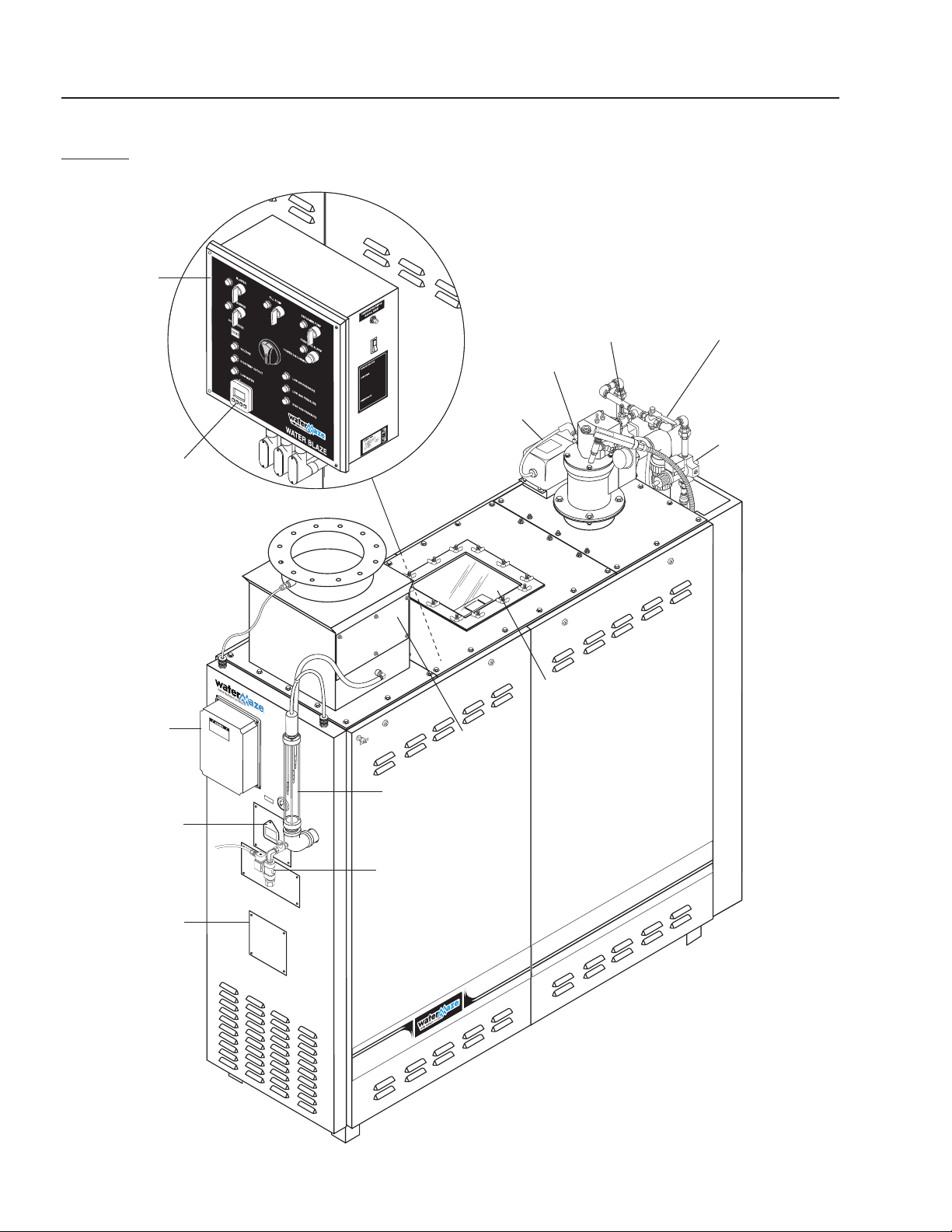
WB-50
FRONT VIEW
89139840-27
Electrical
Box
Glass View
Port
Transformer
3 Point Level
Control Rods
Auto Flush
Flame
View
Port
Photohelic
Gauge
(Option)
Demister
Screens
Spark Plug
Burner Cycle
Timer
Soft Start Gas
Valve Adjuster
(WB-50)
Main Gas Valve
Adjuster
Soft Start
Solenoid
(WB-50)
Level Controls
NEMA Box
Figure 5
WATERMAZE SERIES OPERATOR’S MANUAL
15
WB • 8.913-984.0-N
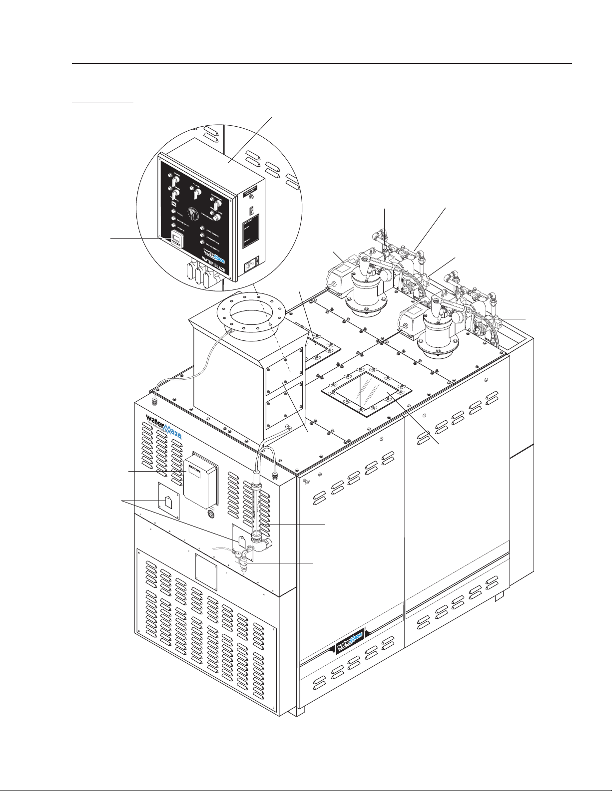
WB-120A
FRONT VIEW
89139840-26
3 Point Level
Control Rods
Demister
Screens
Main Gas Valve
Adjuster Burner 1
Transformer
Electrical
Box
Flame View
Port
UV Scanner
Burner 2
Burner
Cycle
Timer
Soft Start Solenoid
Burner 1
Soft Start Gas
Valve Adjuster
Burner 1
Glass View
Port
Glass
View
Port
Level Controls
NEMA Box
Figure 6
Auto Flush

16
WATERMAZE SERIES OPERATOR’S MANUAL
WB • 8.913-984.0-N
START-UP PROCEDURES
SHUT DOWN PROCEDURES
PANEL PROCEDURE RESULT
Turn on the main disconnect switch #1. Timer (LED screen) lights up.
Press F1/RST (reset button)
#2 on cycle timer.
Powers up the timer (LED screen).
Voltage light comes on.
Turn on the blower switch #3 to
desired position (manual or auto-matic).
“Manual” will bypass the liquid level float
in the customer's holding tank. “Auto-
matic” will allow the float to control the
WATER MAZE
on/off operation of the blower.
Blower light turns on. Water
level in the sight tube will rise
as the water is evacuated
from the sparger tube.
Turn on the burner switch #4. The interlocks are checked and a green light will
be seen on the Veri-Flame. If there is a red light
on the Veri-Flame, there is a problem with one of
the interlocks that must be corrected.
After the interlocks are proven, the blower
will purge the sparger tube for 15 seconds,
then the burner will ignite. If the burner does
not ignite within eight seconds, the “UV scanner”
will shut the system down. At full burner
ignition, burner light turns on.
Turn on the pump switch #5. As water is evaporated, the wastewater
pump will automatically refill the tank.
Turn defoamer switch #6 to auto mode. Anti-foam will be added when fill pump is on.
If more defoamer is needed, turn the feed
adjustment (See page 48, figure 16) clockwise
to increase the speed of defoamer pump.
PANEL PROCEDURE RESULT
(To locate individual items,
please see above.)
Turn defoamer switch
#6 to middle off position.
The defoamer
light goes out.
Turn the pump
switch #5 off.
The pump light goes out. The waste stream
pump shuts down and the solenoid valve closes.
Turn the burner
switch #4 off.
The burner light goes out. The burner shuts
down. The gas solenoid closes and the power
is cut to the transformer preventing a spark.
After turning the burner off, let the blower
run for at least one minute before turning it off.
Turn the blower
switch #3 off.
The blower light goes out. At this point, the
blower shuts down and water from the tank
enters into the sparger tube.
Turn the main
disconnect switch #1 off.
The voltage light goes out. All power to the
evaporator is disconnected except to timer.
The water in the evaporator is still HOT at this
point. Allow the water to cool before any
maintenance is done, i.e., sludge removal.
If the evaporator is to be left off overnight or
longer, shut off the gas supply to the evaporator.
89139840-24
6
3
4
5
1
2
89139840-25

WATERMAZE SERIES OPERATOR’S MANUAL
17
WB • 8.913-984.0-N
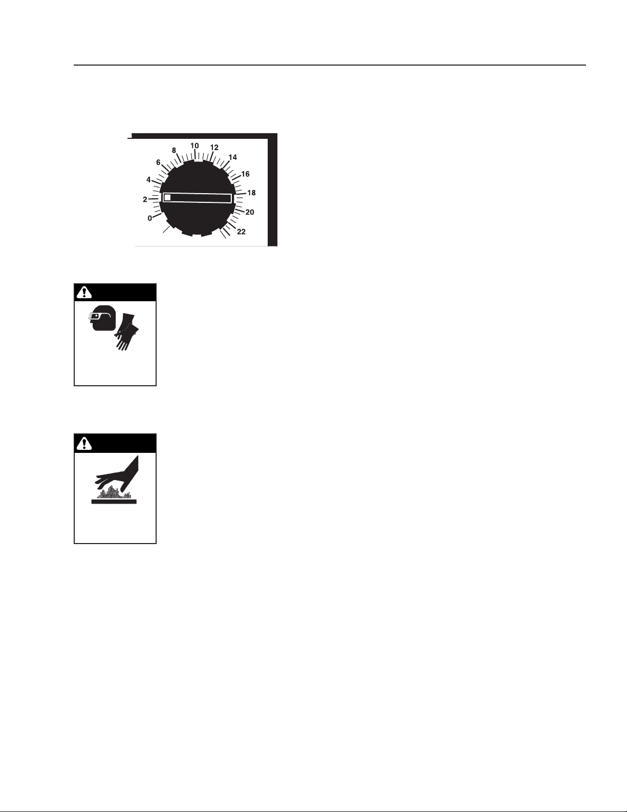
SETTING THE BURNER
The quickest and easiest way to adjust the air and gas
differential to the appropriate settings listed below is to
purchase the WATER MAZE set up kit (#7-8200). Refer
to figure 7 for locations on setting the burner. Shut main
gas valve off. With 7/16" wrench remove brass plugs
from all metering orifices on back side of machine. Install
brass valves included in set up kit into each position
and close. Turn gas main valve back on. To set static
pressure, use 0 - 50 manometer on (D or E). To adjust
setting to desired 45 wci, remove cap on gas regulator
(F) and turn inside adjustment screw clockwise for higher
pressure, counterclockwise for lower pressure. Replace
cap. Start machine by turning the blower switch to the
“auto” position and burner switch to the “on” position.
Once the burner lights, use the 0 - 10 manometer to set
the air differential at (B). Note: lower port is high pres-
sure and upper port is low pressure. With hoses in posi-
tion, open brass valves. Set air differential as per chart
below. Note: needle will shake; pinch both hoses lightly
together to read number. Adjust by opening or closing
main air butterfly and secondary air butterfly (located
on left side of burner, up top). Close brass valves. Set
the gas differential the same way as the air. Note: read
NATURAL GAS:
LIQUID PROPANE GAS:
chart for proper gas used. Attach 0 - 10 manometer at
(C) and set as per chart. The adjustment valve is located
to the right of the burner up top. Remove the brass cap
and adjust with a standard screwdriver. You will have to
set one burner at a time on a WB-120. Once adjusted,
shut off burner and blower. Shut off main gas line. Now
remove the brass valves used with the manometers and
replace plugs into the air and gas orifices. Turn the main
gas back on and follow the procedures for start up. Your
evaporator is now in service.
SOFT START IGNITION
To provide a smooth ignition and meet all gas train
standards, the WB-50 and WB-120 come standard with
the soft start ignition system. Before trial of ignition the
Veri-Flame will make sure the top gas solenoid is closed
(proof of closure). Once closed, the Veri-Flame will try for
a pilot flame. After approximately 8 seconds, the proof
of closure solenoid will close and allow the main gas
solenoid to open slowly.
Soft start settings: The gas metering orifice SBO-A-1
(A) for the soft start needs to be set on 7 wci for the gas
differential. Follow (Setting The Burner) instructions for
setting the soft start gas differential.
UNIT GPH METERING
ORIFICE
GAS
DIFFERENTIAL
METERING
ORIFICE
AIR
DIFFERENTIAL
WB-50A
60 SBO-C-3 5 SBO-677 12
WB-120A
120 SBO-C-3 5 SBO-677 12
UNIT GPH METERING
ORIFICE
GAS DIFFERENTIAL METERING
ORIFICE
AIR DIFFERENTIAL
WB-50A
60 SBO-D-7 5.5 SBO-677 12
WB-120A
120 SBO-D-7 5.5 SBO-677 12
18
WATERMAZE SERIES OPERATOR’S MANUAL
WB • 8.913-984.0-N
WATER MAZE
BURNER ADJUSTMENT
Soft Start
Gas Pipe
High
Static Gas
WB-50/120 Models
Main Gas Pipe
(All Models)
Air/Gas
Differential
Low
High
Main Air Pipe
(All Models)
Low
WB-50/120 Models
Test Valves
Main Air
Valve
Gas
Regulator
Cap
Static Gas
Check Port
High Switch
Low
Switch
Figure 7
WATERMAZE SERIES OPERATOR’S MANUAL
19
WB • 8.913-984.0-N
FOAMING
The WATER MAZE uses a high volume of air to operate
the burner, which pushes the heat out of the sparger
tube and into the evaporation tank. There, the air goes
through baffle screens to break the air bubbles down
into smaller sizes. This process can cause excessive
foaming from the detergent used in the washing process
if it has any kind of foaming agents. This foam interferes
with the evaporation process of the WATER MAZE and
the foam will go up the stack causing problems with the
venting of the WATER MAZE.
The best solution is not to use detergents or cleaning
compounds that cause foaming. An anti-foam pump is
a standard feature on this machine. WATER BLAZE has
defoamer chemicals available, developed for use in the
evaporator.
CONVERTING NATURAL GAS
TO L.P. GAS
WARNING: Before converting
from natural gas to L.P. gas, be
certain that the evaporator is shut
down, the water has been cooled,
the gas line is shut off and the
power is disconnected.
The WATER MAZE can be ordered
from the factory in natural gas or
L.P. gas. Once they are in the field,
you must order a conversion kit to
change from natural gas to L.P. gas
or from L.P. gas to natural gas.
WB-50/120:
The conversion kit for the WB-50/120, natural gas to
L.P, is # 8.906-072.0.
Remove the SBO-D-7 and replace it with SBO-C-3.
(See items 19 and 21 on pages 42 & 43.) Change the
regulator orifice. Remove the 5/8" orifice and replace
with the 1/2" orifice.
To replace the orifice, disconnect the 3/4" gas line at the
unions above and below the metering orifice. Remove
the section of pipe by unscrewing it from the orifice and
then remove the orifice by unscrewing it from the pipe
above it.
Install the new orifice by applying pipe sealant to the
pipe coming from the gas solenoid valve and screw the
orifice to the pipe. Apply pipe sealant to the section of
pipe that was removed and screw it into the bottom of
the orifice. Reconnect at the unions.
NOTE: Be certain that the orifice is installed right side
up or the system will not work properly. The orifice has
an arrow indicating the flow. If there is not an arrow, look
on the side of the orifice where the plugs are located.
One has green paint around it, the other has red paint.
The plug with green paint goes on the top.
Change the regulator orifice in the gas regulator from
1/2" for natural gas to 3/8" for L.P. gas. Remove the
regulator at the unions. The orifice sits in the tee below
the regulator unions. Use a 1" socket with an extension
to remove the orifice. Put the new 3/8" orifice in. Replace
the regulator.
Replace the “Natural Gas Only” label with the “L.P.
Gas Only” label.
Conversion Kits:
8.906-066.0 Factory Conversion from Natural Gas
to L.P. WB-50/120, Qty 2 for WB-120
8.906-072.0 Field Conversion Kit from Natural Gas
to L.P. WB-50/120, Qty 2 for WB-120
8.906-069.0 Field Conversion Kit from L.P. to Natural
Gas WB-50/120, Qty 2 for WB-120
Standard WATER MAZE machines are natural gas fired
and are so constructed. When propane fuel is specified
please add the appropriate conversion part number to
the order. Thank you.
WARNING
RISK OF FIRE,
EXPLOSION OR
SERIOUS BURNS:
SHUT DOWN UNIT,
SHUT OFF GAS LINE
AND DISCONNECT
POWER BEFORE
CONVERTING.
20
WATERMAZE SERIES OPERATOR’S MANUAL
WB • 8.913-984.0-N
The Veri-Flame is the controller which proves all of the
interlocks. It provides for a purge cycle to insure that
there are no combustibles in the sparger tube before
the trial for ignition (TFI). The length of the purge cycle
is determined by the settings on the Veri-Flame. It is
preset at the factory for 15 seconds.
If you need to check the settings on your Veri-Flame
or if you replace a Veri Flame and it needs to be set,
remove the screws holding the cover on and unplug the
cover from the back. Dipp switches are located on the
reverse side. Set the eight switches as follows: switch 1
ON, switch 2 OFF, switch 3 ON, switch 4 ON, switches
5, 6, 7 and 8 OFF.
If switch 1 is ON, the burner will recycle once after an
air or main flame failure. Otherwise, the system will shut
down.
A pilot light is not used so switch 2 is set to OFF. Switch
3 controls the amount of time the machine has for TFI.
With this switch set to ON, the machine has 10 seconds
for TFI. Switches 4 through 8 control the amount of
purge time before TFI. Switch 4 gives the machine a 15
second purge before TFI.
A Veri-Flame and U.V. scanner tester is available
(#7-8063).
3 POINT SENSOR CONTROL
The 3 point sensor control is part of the safety interlock
system and also controls the wastewater air diaphragm
pump.
The bottom rod is the low water safety position. If the
wastewater level is too low, this rod, working through the
Veri-Flame, will not allow the burner to ignite. When the
wastewater level drops to the position of the middle rod,
there is a demand for water and the wastewater pump
turns on. The air diaphragm pump continues to run until
the top rod is reached by the wastewater. At this point
the pump shuts off. When the level drops to the middle
rod, the wastewater pump restarts again.
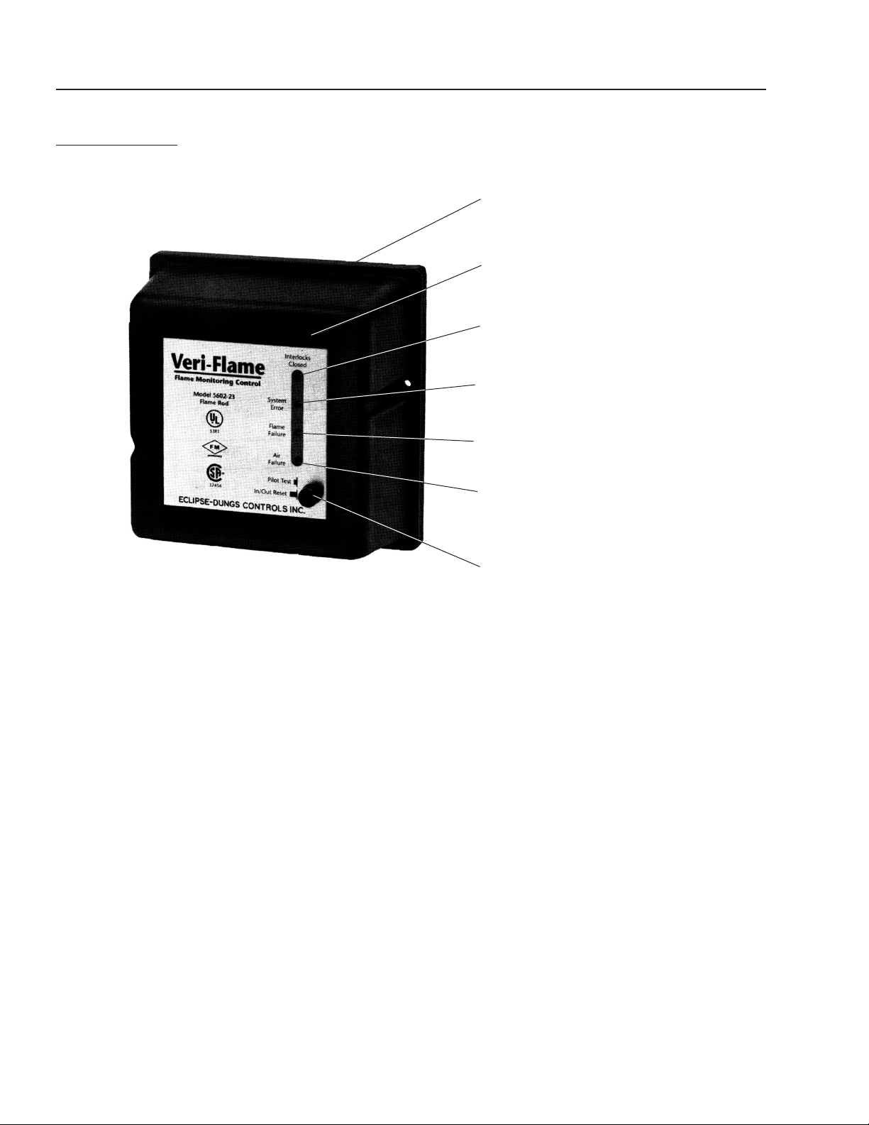
VERI-FLAME
#7-8061
"Flame Signal" – should be red
Button in "Out" position
"Air Failure" – Blower
"Flame Failure" – UV Scanner
"System Error" – These are your
interlocks, this light shouldn't be
illuminated, if it is check interlocks.
"Interlocks Closed" – should be green
Dipp Switches
Figure 8
WATERMAZE SERIES OPERATOR’S MANUAL
21
WB • 8.913-984.0-N
SETTING LIMIT CONTROL
Adjust the high limit control temperature accordiningly.
MAINTENANCE
WARNING: Use protective gloves,
goggles and any other protective
clothing according to the MSDS
reports of chemicals mixed with
the waste stream.
The WATER MAZE does not require
a lot of maintenance, but it does
require consistent maintenance. The frequency of main-
tenance will vary depending on what is in the water that
is being evaporated.
WARNING: Shut down the WATER
MAZE and allow it to cool before
performing maintenance.
General maintenance will consist
of removal of any floating oil in the
evaporation tank, removal of sludge
from the evaporation tank and the
sparger tube, removal and cleaning
of the liquid level switch and sight
tube, cleaning the UV scanner and the ignition plug.
Daily Maintenance Procedures:
1. Turn WATER MAZE wastewater pump, burner and
blower to the off position.
2. Turn WATER MAZE main power disconnect to the
off position before initiating maintenance.
3. Connect garden hose to garden hose fitting at the
elbow of the liquid level control sight glass. Turn on
water, set timer in electrical box for 10 seconds to
flush elbow and nipple.31
Weekly Maintenance Procedures:
1. Turn the WATER MAZE wastewater pump, burner
and blower to the off position.
2. Turn the WATER MAZE main power disconnect to
the off position before initiating maintenance.
3. If oil removal is necessary, you can remove the oil
by removing the access window on the top of the
machine and using a shop vacuum to remove the
oil.
4. With a sludge catch container in place, open the
1-1/2" sludge ball valve to remove accumulated
sludge and concentrated liquid from the WATER
MAZE tank.
5. When you are sure the water level is below the sparg-
er tube, remove the panel that covers the clean out
flange and open the sparger tube clean out access
flange. With the supplied tool kit, remove any solids
from the inner diameter of the tube and sparger
slot. Place the removed solids in a holding con-
tainer in accordance with disposal regulations. When
cleaning of the sparger tube is completed, in-
spect
the inside of it for any deterioration. Reassemble the
sparger tube, clean out flange and cover panel.
6. Inspect the inside of the WATER MAZE tank, screens
and outside of the sparger tube for any build up of
solids. This can be done by removing the glass ac-
cess window on the top of the machine. Remove
solids build up if necessary. Replace window and
bezel when completed.
7. Remove the demister box access door and inspect
screens. If the screens have a build up of solids,
remove the screens and clean the inside of the
demister box and screens. Reassemble the screens
in the demister box and reattach the access door.
8. Remove the 3 point level controller rods by removing
the three 3/8" nuts on top of the upper body sight
glass holder and slide straight upward. Clean rods
with rag. Use a Scotch Brite pad for bottom end of
rods.
9. Remove sightglass and clean out hole in lower
sightglass holder. If plugged, remove lower sight
glass holder from elbow and flush with freshwater.
10. Shut off the wastewater inlet valve (not supplied)
located near the wastewater inlet. Unscrew the filter
housing and remove the 20 mesh filter screen. Clean
and replace the screen. Screw the filter housing back
into place and open the wastewater valve.
Monthly Maintenance Procedures:
1. Turn the WATER MAZE wastewater pump, burner
and blower to the off position.
2. Turn WATER MAZE main power disconnect to the
off position before initiating maintenance.
WARNING
TURN OFF MACHINE
AND ALLOW TO
COOL BEFORE
SERVICING.
WARNING
WEAR PROTECTIVE
EYEWEAR, GLOVES
AND CLOTHING.
230° for the WB-50/WB-120

22
WATERMAZE SERIES OPERATOR’S MANUAL
WB • 8.913-984.0-N
3. Turn waste source off. Drain tank after evaporating
until low water shut off.
4. Remove top lid of the WATER MAZE and thoroughly
inspect the interior of the tank and sparger tube.
Remove any solids that may have built up on the
interior of the tank, sparger tube and air distributor.
Rinse the interior of the tank.
5. Remove the ignition plug wire from the ignition plug.
Remove the ignition plug from the burner and clean.
Inspect the ignition plug for any cracks in the insula-
tion. If cracks are found, replace the ignition plug.
6. Remove the U.V. scanner from the burner, inspect
and clean the lens.
7. Refill the WATER MAZE tank with water to the
minimum restart liquid level. Restart the blower and
burner and verify the air/gas ratios with manometers
for proper operation of the burner.
8. Thoroughly clean the following: 3 point level control-
ler rods, glass tube, demister screens, wastewater
filter and housing.
Semi-Annual Maintenance Procedures:
1. Turn the WATER MAZE water pump, burner and
blower to the off position.
2. Turn the WATER MAZE main power disconnect to
the off position before initiating maintenance.
3. Turn waste source off. Drain tank after evaporating
until low water shut down.
4. Remove top lid of the WATER MAZE and thoroughly
inspect the interior of the tank and sparger tube. Re-
move any solids that may have built up on the interior
of the tank and sparger tube. Rinse the interior of
the tank.
5. Inspect the blower for proper operation. Check the
amp draw, bearing noise and inlet screen.
6. Inspect the wastewater pump for proper operation.
Also check for possible leaks in the housing.
7. Inspect hoses for any deterioration.
8. Loosen the air/gas line unions and remove the
burner from the mounting flange. Clean the nozzle
inside the burner with a small steel brush removing
any build up that is obstructing the mixing of the air
and gas through the nozzle. Replace the burner
mounting gaskets with new gaskets each time the
burner is removed.
9. Refill the WATER MAZE tank with water to the
minimum restart liquid level. Restart the blower and
burner and verify air/gas ratios with manometer for
proper operation of the burner.
Chlorides/Fluorides
Water evaporation tends to concentrate non-volatile
solids in a waste stream. Thus chlorides, fluorides and
related corrosion increase as the volume of the waste
stream decreases. In order to obtain the maximum life
from the WATER MAZE, it is important to monitor the
chloride and fluoride content of the liquid in the evapora-
tion tank, so the waste can be purged prior to damage
by chloride or fluoride corrosion.
Clean Screen:
Shut off the wastewater valve (not included) located near
the “wastewater inlet” on the back end panel. Unscrew
the filter housing and remove the 20 mesh filter. Clean
and replace the screen. Screw the filter housing back
into place and open the wastewater valve (See figure 3).
Clean U.V. Scanner & Ignition Plug:
Once a month, the UV scanner needs to be removed and
cleaned, usually by wiping the scanner off with a cotton
swab and replacing it. Also every month remove the igni-
tion plug and clean it. Check for damage or wear.
Demister Box Screens:
Remove the screens from the demister box and clean
them off. Replace them in the demister box. Make sure
that the door is secure and the gasket is good so that
there are no leaks.
Anti-Foam Maintenance:
CAUTION: Do not attempt to feed chemicals without
consulting your chemical feeder dealer or chemical
supplier.
1. Filling the Chemical Tank
To avoid running out of chemical, follow a regular
schedule of monitoring the chemical supply. Also
inspect and clean the strainer by flushing with a
compatible liquid, as needed.
2. Tubing Inspection
Inspect all tubing regularly and replace it if deteriorat-
ing. Follow the instructions with figure 10 to replace
the pump head tubing.
3. Feeding Adjustment
The feed adjustment is under the front cover. Re-
move the cover and turn the screw clockwise to
increase the feed or counterclockwise to decrease
the feed. Replace the enclosure cap after making
the adjustment. NOTE: Always start with the lowest
feed rate. (See figure 10). Lower feed rate pumps
are available.
WATERMAZE SERIES OPERATOR’S MANUAL
23
WB • 8.913-984.0-N
A
D
B
C
Bucket
(Not Included)
E
F
4. On/Off/ Full Speed Switch
Now that the system is adjusted, turn the pump on.
The pump will come on and inject “anti-foam” into the
waste stream when the wastewater pump comes on.
The Full Speed setting can be used to fill the feed
lines more quickly.
Sludge Removal:
Remove the doors on the right side of the WATER MAZE.
At the bottom of the evaporation tank you will find a
1-1/2" ball valve. Connect a hose to the valve and place
the other end into a container. Open the valve and flush
out the sludge. If nothing comes out, you may need to
run a wire into the valve to break loose the sludge that
has collected in the evaporation tank. Once the sludge
has been drained, close the valve.
NOTE: Drain water level below the sparger tube before
removing item E (See figure on page 23).
Sparger Tube Cleaning:
The tool kit, (8.903-719.0), consists of four items. Check
to ensure that the kit is complete (refer to the drawing).
A. Tool handle (2 pc.)
B. Probe/scraper
C. Trough assembly
Remove the panel that covers the flange assembly (this
cover is not shown in this drawing). Use a 3/4" socket to
remove the nuts holding the front of the flange assembly
(E) from the rear flange assembly (D). Also remove the
gasket and check it for damage or wear.
Next, place the trough assembly (C) onto the bottom
two studs of the rear flange (D) and replace the nuts to
hold it securely in place. Assemble the tool by screwing
the tool handle (A) into the probe/scraper (B). Place the
probe/ scraper tool as far back into the sparger tube as
possible. While pulling the scraper forward, scrape out all
of the buildup that has accumulated inside of the sparger
tube (H) and direct it into the slot of the sparger tube.
Continue until the sparger is clean. Clean out the slot (F)
inside the sparger tube. Remove sludge from the bottom
of the tank monthly.
Once this is completed, remove the probe/scraper and
the trough assembly (C). Make sure the gasket is clean
along with the surface area between the front flange (E)
and the rear flange assembly (D). Place the gasket over
the studs on the rear flange assembly and then do the
same with the front flange assembly (E). Use the 1/2"
nuts to secure the flange assembly. Refill the evaporator
tank and check the flange assembly for leaks. Replace
the panel that covers the flange assembly.
Figure 9
H

24
WATERMAZE SERIES OPERATOR’S MANUAL
WB • 8.913-984.0-N
PROGRAMMING OF
WATER MAZE CYCLE TIMER
Function Settings
Reset Button. Push to restart machine after
batch cycle completed.
Scroll Button. Push to select the different pro-
gramming modes. Also saves program values.
Vertical Scroll changes programming values.
Horizontal Scroll for multiple values. Also
changes programming values.
Programming
1. Press and hold button for 2 seconds. (Entry)
will appear in red. (Auto Sc) will appear in green.
No change is necessary.
2. Press button once, (trAngE) will appear in red.
Press ▲ button until (h.n.O) appears in green.
3. Press button, (OPEr) will appear in red. Press
▲ button until (31) appears in green.
4. Press button, (rSt.P.uP) will appear in red. (no)
will appear in green. No change is necessary.
5. Press button, (Ac Pr S) will appear in red. (-N-
N) will appear in green. Press button until far left
(-y) is blinking. Press ▲ button until (-n) appears.
Press button once more and the right (-y) will
blink. Press ▲ button until (-n) is showing.
6. Press button, (PrESEt) will appear in red. The
value to set is predetermined from the wastewater
analysis. This value is known as PRS1(Preset 1).
Press the ▲ or buttons until the burner time is
achieved.
7. Press button, (PrESEt) will appear in red. This
value,PRS2(Preset 2) must be set with the same
value as (Preset 1). Press the ▲ or buttons to
set value.
8. Press button, (PltrAc) will appear in red. (no)
will appear in green. No change is necessary.
9. Press button, (Ac Out) will appear in red. (-L-L)
will appear in green. Press button until the far left
(-L) value is blinking. Press the ▲ button until
(-n) appears. Press the once more and the right
(-L) will blink. Press the ▲ button until (-n) is show-
ing.
10. Press button, (OutrES) will appear in red. Press
the ▲ button until (0.1 SEC) appears in green.
11. Press button, (OutPut) will appear in red. This
value is the autopurge valve #1. For WB-25 or WB-
50, this value needs to be set at (300) seconds. For
WB-120 the value is (999) seconds. Press the ▲ but-
ton until the correct value for your machine appears.
12. Press button, (OutPut) will appear in red. This
value, auto purge valve #2, must be set with the
same value as autopurge valve #1. Press ▲ or
buttons to set value.
13. Press button, (rEUOut ) will appear in red.
(-n-n) will appear in green. Press the until the
far left (-n) blinks. Press the ▲ button once and the
(-y) appears.
14. Press button, (rEUAnu) will appear in red.
(-n-n) will appear in green. No change is neces-
sary.
15. Press button, (OutP.uP) will appear in red.
(-F-F) will appear in green. No change is neces-
sary.
16. Press button, (USr In 1) will appear in red.
(rst -L) will appear in green. Press ▲ button until
(Pro.diS) appears.
17. Press button, (USr In 2) will appear in red.
(rSt -L) will appear in green. No change is neces-
sary.
18. Press button, (USr In 3) will appear in red.
(rSt -L) will appear in green. No change is neces-
sary.
19. Press button, (USr FI) will appear in red.
(rSt -L) will appear in green. Press ▲ button until
(rStOut) appears.
20. Press button, (CodE) will appear in red.
(0) will appear in green. No change is necessary.
21. Press button, (ScroLL) will appear in red.
(no) will appear in green. No change is necessary.
22. Press button, (FAcSEt) will appear in red.
(no) will appear in green. No change is necessary.
23. Press and hold button for 2 seconds. (Prog)
will appear in red and (SAVE) will appear in green.
To complete setting the timer, first pull the face plate
of the timer out of its holder with your fingers. This will
expose the internal circuit boards. Along the left side
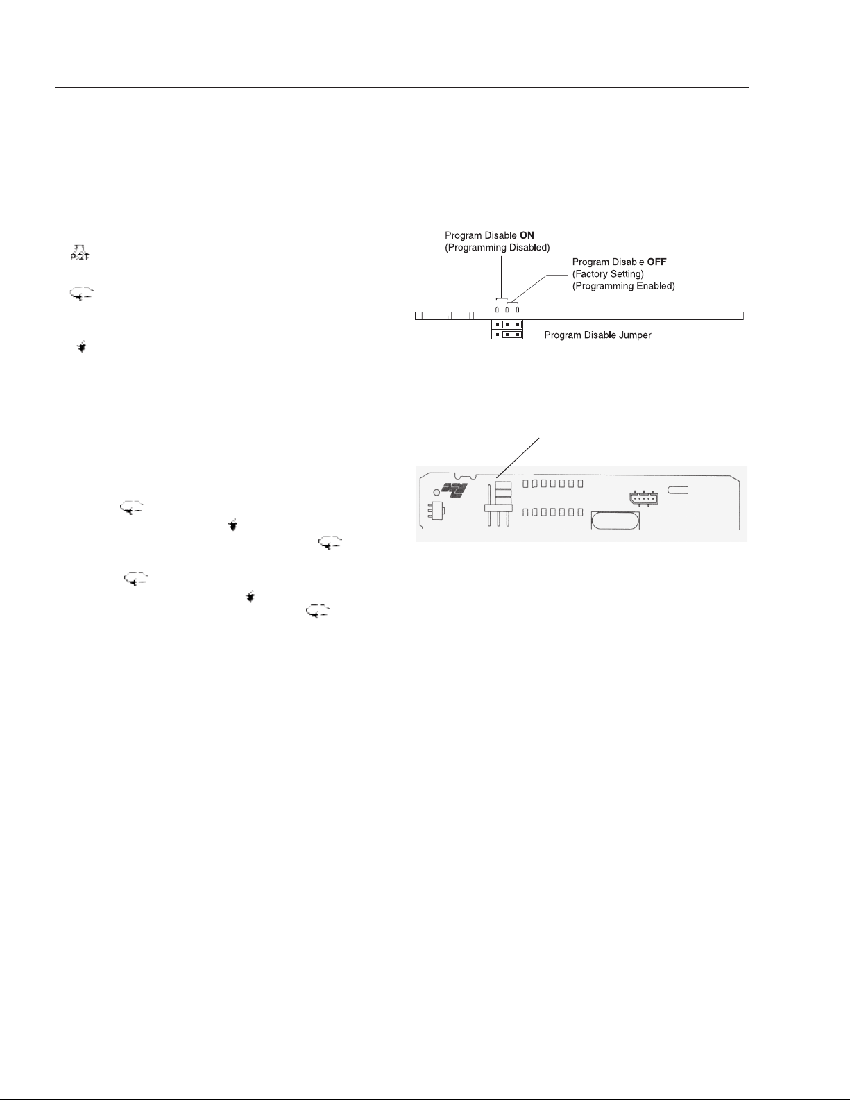
(wall) you will see two (blue) jumpers. Pull upward on
the blue jumper not touching the side wall and move
it forward one position on the pins. This is the lock out
mode for the timer.
Slide the timer back into its holder. Initial programming
of the timer is complete. Once power is supplied to
the timer via the main disconnect on the Water Maze,
the button must be pushed to set the timer in
run mode.
NOTE: Reprogramming can not be preformed with the
blue disable jumper in the forward position. Remember,
if reprogramming is to be done, always place the disable
jumper in the most forward position when done.
NOTE: Original cycle timer has been preset at
factory.
▲

WATERMAZE SERIES OPERATOR’S MANUAL
25
WB • 8.913-984.0-N
SETTINGS CHART
MODE VALUE SETTING
Entry Auto Sc
trAngE h.n.O
OPEr 31
rSt.P.uP no
Ac PrS -n-n
PrESEt Customer run time value #1
PrESEt Customer run time value #2
PltrAc no
Ac Out -n-n
OutrES 0.1 SEC
OutPut Auto purge run time value #1
OutPut Auto purge run time value #2
rEUOut -y-n
rEUAnu -n-n
OutP.uP -F-F
USr In 1 Pro.diS
USr In 2 rSt -L
USr In 3 rSt -L
USr F1 rStOut
CodE O
ScroLL no
FAcSEt no
26
WATERMAZE SERIES OPERATOR’S MANUAL
WB • 8.913-984.0-N
WATER MAZE CYCLE TIMER
QUICK REPROGRAMMING
INSTRUCTIONS
Function Settings
Reset Button. Push to restart after power
outage.
Scroll Button. Push to select the different pro-
gramming modes. Also saves program values.
Vertical Scroll changes programming values.
Horizontal Scroll for multiple values. Also
changes programming values.
Programming
1. Pull face plate of timer out of its holder in electrical
box with your fingers. Along the left side (wall) of
the circuit board, the blue disable jumper needs to
be pulled upward and moved back one pin position.
This will allow for reprogramming. Slide timer back
into its holder.
2. Press button until LED screen in green shows
(
PRS #02
). Push the ▲ or button until the new run
time appears in green Then press the button
once to save the setting for preset 1.
3. Press button once more. The LED screen will
show (
PRS #02
). Push the ▲ or until the value in green
is the same value as preset 1. Press button to
save setting for preset 2.
4. Remove timer once again from its holder in the elec-
trical box. Change the blue disable jumper back to
the most forward pin position. Slide the timer back
into its holder in the electrical box.
▲
Program Disable Jumper Settings
Program Disable Plug Jumper
The program disable plug jumper is used to enable and
disable front panel programming. The plug jumper is
located on the CPU board.
User Input and Program Disable Jumper Locations
User Input and Program
Disable Jumper Locations
FIGURE 10
WATERMAZE SERIES OPERATOR’S MANUAL
27
WB • 8.913-984.0-N
ITEM PART NO. DESCRIPTION QTY
1 8.755-211.0 Controller, Level,
Z-Tron IV, LL/HL 3
2 9.802-064.0 Grommet 1
3 8.716-300.0 Sensor, Capacitance,
3 Point 1
4 8.716-290.0 Box, Plastic, 9.8 x 6.8 x 5.61 1
8.716-291.0 ▲ Plate, Back 1
9.802-515.0 ▲ Strain Relief, Strt,
LQ Tite 1
8.913-230.0 ▲ Bracket, Controller
Mount 1
WATER MAZE
WATER LEVEL CONTROL UNIT
ITEM PART NO. DESCRIPTION QTY
5 8.706-051.0 Nipple, 1/2" Close, 316L SS 1
6 9.802-146.0 Swivel, 1/2" MP x 3/4" GHF
w/Strainer 1
7 8.751-320.0 Swing Check Valve, 316 SS 1
8 8.706-208.0 Street Elbow, 1/2" MPT x 1/2"
FPT 1
9 8.706-790.0 Nipple, 1/2" Close 1
10 8.713-149.0 Solenoid Valve/ 1/2" 1
11 9.802-422.0 Cord Service, SEO 16/2 7 ft.
12 9.802-514.0 Strain Relief, LT, 1/2" 1
▲ Not Shown
1
1
4
6
5
3
12
11
10
7
8
9
2

28
WATERMAZE SERIES OPERATOR’S MANUAL
WB • 8.913-984.0-N
WB-50A
EXPLODED VIEW LEFT SIDE
13
125
1
82
80
81
83
84
40
14
17,125,126
15
16
124
37
41
148
149
98
41
125
79
150
36
123
32
34,124,125
31
33
29
For
Detail
See Air
Line Assy.
Illus.
21
135
136
130
131
89
90
3
121
2
129
4
5
7
91
10
122
6
11
116
106
8
92
35
52
127
128
20
18
19
53
126
126
103
105
104
137
112
142
143
144
72
71
113
72
WATERMAZE SERIES OPERATOR’S MANUAL
29
WB • 8.913-984.0-N
WB-50A
EXPLODED VIEW RIGHT SIDE
For
Detail See
Electrical
Box Illus.
78
30
145, 146, 147
53
44
44
69
38
67
12
27
25
26
73
24
56
109
74
75
97
69
54
73
25
97
67
110
111
23
9
22
101
95
120
86
138
96
73
139
73
25
55
43
65
109
64
46
119
49
64
77
108
117
51
108
115
61
140
107
87
93
39
58
47
69
59
57
66
67
48
60
For Detail
See Gas
Plumbing
Assy.
Illus.
#30-844
Option
133
131
132
For
Detail
See Gas
Plumbing
Assy. Illus.
For
Detail See
Air Line
Assy.
Illus.
85
76
99
100
62
63
68
114
118
45
102
50
134
88
140
138
138
55
55

30
WATERMAZE SERIES OPERATOR’S MANUAL
WB • 8.913-984.0-N
WB-50A
EXPLODED VIEW PARTS LIST
ITEM PART NO. DESCRIPTION QTY
1 8.913-019.0 Baffle, Screen 5
2 8.912-987.0 Panel, Control End 1
9.802-791.0 ▲ Nut, Cage, 10/32" x 16 GA 8
3 8.724-680.0 Label, WATER MAZE
Wastewater Evaporators 3
4 8.716-300.0 Sensor, Capacitance, 3 Point 1
8.707-383.0 ▲ Gasket, Sight Glass Tube 2
8.706-757.0 Tube, Sight Glass 1
8.900-583.0 ▲ Label, Level Control 1
5 8.719-976.0 Body, Sight Glass, Upper,
Brass 1
8.719-977.0 Body Sight Glass, Upper,
304L 1
6 8.719-972.0 Body, Sight Glass, Lower,
Brass 1
8.719-973.0 Body, Sight Glass, Lower,
304L 1
7 8.719-974.0 Rod, Sight Tube, Brass,
1/4" x 12.5" 3
8 8.716-571.0 Strain Relief, 1/2" LQ Tite 2
9.802-524.0 ▲ Locknut, 1/2" Conduit 1
9 8.712-157.0 Gauge, Thermometer 1
8.706-806.0 ▲ Nipple, 1/4" x 2-1/2", 316L 1
8.706-813.0 ▲ Coupling, 1/4" Hex, 316L 1
10 8.913-025.0 Plate, Observation 1
9.802-759.0 ▲ Screw, 10/32" x 1/2"
BHSOC Black 5
9.804-567.0 ▲ Nut, 10/32", ESNA 1
11 8.913-010.0 Cover, View Port 1
9.800-028.0 Label, Pilot Light Hole 1
12 8.706-958.0 Hose Barb, 90°, 1/4" Barb
x 1/4" Pipe 3
13 8.913-033.0 Box, Demister Assy, 316L 1
8.913-034.0 Box, Demister Assy, AL-6XN 1
14 8.913-015.0 Lid, Center Plate, 316L 1
8.913-016.0 Lid, Center Plate 1
15 8.912-972.0 Bezel 1
8.707-382.0 ▲ Gasket, Bezel, All, Buna-n 2
16 8.706-758.0 Cover, Tempered Glass 1
17 8.718-906.0 Nut, 3/8" Wing, SS 8
18 8.913-027.0 Cover Plate w/Viewer 1
19 8.707-397.0 Gasket, Cover Plate, Silicone 1
20 8.718-201.0 Glass, Site, Observation 1
ITEM PART NO. DESCRIPTION QTY
21 8.715-190.0 Blower, Regenerative, 2.5 HP
R-6125 1
8.709-083.0 ▲ Clamp 1
9.802-066.0 ▲ Pad, Soft Rubber 4
9.802-819.0 ▲ Washer, 7/16" x 2-1/2",
Zinc 4
22 8.913-000.0 Tank, Assy, SS 316L 1
8.913-001.0 Tank, Assy, AL-6XN 1
8.913-002.0 Tank, Assy, Duplex 1
8.707-385.0 ▲ Gasket, Tank Cover 1
23 8.912-976.0 Base, Assy 1
8.913-005.0 ▲ Raceway, Electrical 1
8.913-006.0 ▲ Raceway, Cover 2
24 8.716-689.0 Valve, Solenoid, 120V 1
25 9.802-533.0 Solenoid, Coil, 120V 3
26 8.716-690.0 Solenoid, Coil, 120V 1
27 8.716-691.0 Valve Solenoid, 120V 3
28 8.706-475.0 Union, CPVC 80, 1-1/4" 1
29 8.706-474.0 Union, CPVC 80, 2" 2
30 8.717-748.0 Regulator, Rockwell, 3/4" 1
8.718-172.0 ▲ Orifice, Regulator, 1/2", LP 1
30 8.718-173.0 ▲ Orifice, Regulator, 5/8", NG 1
31 8.912-005.0 Burner, Sparger Tube
Assy, 316L 3
8.912-006.0 Burner, Sparger Tube Assy,
AL-6XN 1
32 8.912-008.0 Distributor, Air, 316L 1
8.912-009.0 Distributor, Air, AL-6XN 1
33 8.912-014.0 Bracket, WB Distributor
Mnt. Ring, 316L 2
8.912-015.0 Bracket, WB Distributor
Mnt. Ring, AL-6XN 2
34 9.802-715.0 Bolt, 3/8" x 1" HH NC, 316L 4
9.802-808.0 ▲ Washer, 3/8" SS, Flat 4
8.719-024.0 ▲ Washer, 3/8" SS, Lock 4
8.719-089.0 ▲ Nut, 3/8" Hex, NC, 316L 4
35 8.906-087.0 Single, Ignition Wire 1
36 8.718-177.0 Transformer, Ignition, 120V 1
37 8.718-185.0 Ignition Plug, 16946-5,
Eclipse 1
38 8.718-182.0 Valve, Gas Solenoid, 3/4" 1
▲ Not Shown

WATERMAZE SERIES OPERATOR’S MANUAL
31
WB • 8.913-984.0-N
WB-50A
EXPLODED VIEW PARTS LIST CONTINUED
ITEM PART NO. DESCRIPTION QTY
39 8.716-321.0 Box, Junction 3 Hole, 1/2" 2
8.716-324.0 Box, Junction 4 Hole, 1/2" 1
9.802-483.0 Cover Plate, Junction Box,
2" x 4" 3
8.670-187.0 ▲ Switch, Float, N/O 1
40 8.718-159.0 Burner, Eclipse 1
41 8.718-174.0 Scanner, UV, All 1
42 8.718-166.0 Tube, Combustion 1
8.718-187.0 ▲ Gasket, Burner Eclipse, 7" 2
43 8.706-334.0 Union, 1/2" Black Pipe 1
44 9.802-049.0 Union, 3/4", Black Pipe 5
45 8.718-180.0 Valve, Gas Solenoid, 1/2",
MVDLE, Soft Start 1
46 8.718-181.0 Valve, Gas Solenoid, 3/4",
MVDLE 1
47 8.718-167.0 Orifice Metering, 3/4",
SBO-D-7 (WB-50 {NG}) 1
8.718-169.0 Orifice Metering, 3/4",
SBO-C-3 (WB-50 {LP}) 1
48 8.718-171.0 Orifice Metering, 3/4",
SBO-A-1 1
49 8.718-170.0 Orifice Metering, 2",
SBO-677 1
50 8.718-161.0 Valve, Butterfly, 1-1/4" 1
51 8.718-162.0 Valve, Butterfly, 2" 1
52 8.707-239.0 Valve, Swing Check, Brass, 2" 1
53 8.718-179.0 Switch, Gas & Air Pressure 3
54 8.707-227.0 Valve, Ball, Brass, 1-1/2", 316L 1
55 8.712-172.0 Switch, Thermostat 3
56 9.802-131.0 Elbow, 90°, 1/2" JIC x 1/2" 1
57 8.707-235.0 Valve, Swing Check, Brass,
1/2" 1
58 8.919-139.0 Pump, Peristaltic, 8-45 gpd,
Sekokem 1
59 9.802-128.0 Nipple, 1/2" JIC x 1/2" 1
60 8.912-986.0 Panel, Burner End 1
61 8.912-989.0 Panel, Valve Access 1
62 8.707-000.0 Connector, Anchor, 1/2" 1
9.802-131.0 Elbow, 1/2" JIC x 1/2" 2
63 8.707-331.0 Filter, Regulator,
1/2" w/Gauge
1
64 9.802-146.0 ▲ Swivel, 1/2" MP x 3/4" GHF 2
8.706-970.0 ▲ Swivel, 3/4" Fem HS x
3/4" Female 1
65 8.709-179.0 Filter, 3/4" x 20 Mesh 1
66 9.802-052.0 Bulkhead, 3/4" Poly Pro 1
ITEM PART NO. DESCRIPTION QTY
67 9.802-152.0 Swivel, Push-on, 3/4"
JIC Fem 4
68 9.802-261.0 Hose, Push-on, 3/4" 3 ft.
69 9.802-151.0 Swivel, Push-on, 1/2"
JIC Fem 4
70 9.802-259.0 Hose, Push-on, 1/2" 12 ft.
71 8.749-817.0 Washer, Split Ring 12
72 8.718-996.0 Washer, 3/4 24
73 8.706-777.0 Nipple, Close, 1/4" 2
74 8.715-278.0 1/2" Air Diaphram Pump,
Polypro 1
75 8.715-279.0 1/2" Air Diaphram Pump, SS 1
76 9.803-557.0 Elbow, 90°, 3/4" JIC x 3/4" 4
77 8.707-210.0 Valve, 1/2" Ball, 316 SS 1
78 9.802-792.0 Nut, Cage, 3/8" x 12 Gauge 30
79 9.802-721.0 Bolt, 3/8" x 1" S/S NCHH,
316 SS 30
80 8.913-028.0 Demister, Door 1
81 9.804-573.0 Nut, 1/4", SS NC 6
82 8.718-568.0 Washer, 1/4", Flat, SS,
Sealing Rub 6
83 8.707-391.0 Gasket, Demister Box Door 1
84 8.913-031.0 Screen, Demister, AL-6XN 2
85 8.706-483.0 Bulkhead Fitting, 3/4" 2
86 8.749-860.0 Check Valve, PVC, 1/8" MP 1
87 8.706-941.0 Hose Barb 1/4" x MPT 1/4" 3
88 9.802-254.0 Hose, 1/4", Push-on 8.25 ft.
89 8.706-435.0 Tee, 2" S x S 1
90 8.707-361.0 Valve, 1-1/2" S x S 1
91 8.912-983.0 Door Panel, Right Side 1
92 8.912-982.0 Door Panel, Left Side 1
8.912-981.0 ▲ Door Panel, Side 2
93 8.715-191.0 Manifold, Air, All 1
8.706-965.0 ▲ Hose Barb, 1/4" Barb x
3/8" ML Pipe, 90° 1
8.716-691.0 ▲ Valve, Solenoid, Parker 1
93 8.706-941.0 ▲ Hose Barb, 1/4" Barb x
1/4" ML Pipe 4
8.706-777.0 ▲ Nipple, 1/4" Close 2
8.706-913.0 ▲ Bushing, 3/8" x 1/4" Pipe 1
8.706-829.0 ▲ Elbow, 1/2" Street, Brass 1
8.706-999.0 ▲ Connector, 1/4" Anchor 1
8.706-865.0 ▲ Plug, 1/4" Countersunk 1
▲ Not Shown

32
WATERMAZE SERIES OPERATOR’S MANUAL
WB • 8.913-984.0-N
WB-50A
EXPLODED VIEW PARTS LIST CONTINUED
ITEM PART NO. DESCRIPTION QTY
94 8.706-827.0 ▲ Nipple, 1/4" Close 1
95 8.706-858.0 Tee, 1/4" Street 2
96 8.707-341.0 Valve, In-line Metering 1
97 8.706-898.0 Nipple, 3/4" JIC x 1/2" MPT,
316L 2
98 8.716-547.0 Connector, 1/2" L/T,
Straight, Black 1
99 8.706-846.0 Tee, 3/4" Female, Pipe 1
100 8.707-243.0 Valve, Vacuum Relief, 3/4" 1
101 8.712-155.0 Gauge, Pressure, 0-10 PSI 1
102 8.718-178.0 Switch, Proof of Closure 1
103 8.706-857.0 Tee, 1/8" Street 1
104 8.706-940.0 Hose Barb, 1/4" Barb x
1/8" Pipe 1
105 8.706-955.0 Hose Barb, 1/4" Barb x 1/8"
Pipe, 90° 1
106 8.718-200.0 Switch/Gage,
Capsu-Photohelic Pressure 1
107 8.706-999.0 Connector, 1/4" Anchor 1
108 8.706-790.0 Nipple, 1/2" Close 2
109 8.706-881.0 Nipple, 3/4" Pipe x 1/2" Pipe 2
110 8.719-969.0 Cover, WB Clean Out
Port, 316L 1
8.707-399.0 Gasket, Flange, Cleanout 1
111 8.706-887.0 Elbow, 3/4" JIC x 3/4" 1
112 8.913-074.0 Elbow, 1-1/2", Clean Out 316L 1
8.913-076.0 Elbow, 1-1/2", Clear Out
AL-6XN 1
113 8.718-877.0 Nut, 3/4, Hex 12
114 9.802-132.0 Elbow, 3/4" JIC x 1/2" 1
115 8.706-832.0 Elbow, 3/4" Street 1
116 8.707-145.0 Nipple, 1-1/2" x 4" 316L 1
117 8.706-844.0 Tee, 1/2" Female 1
8.906-084.0 ▲ Water Maze Set Up Kit 1
8.903-719.0 ▲ Tool Kit, Complete, Evap. 1
8.719-138.0 ▲ Defoamer, WATER MAZE
5600 1 gal.
118 8.718-894.0 Nut, 7/8" SS 8
8.718-998.0 Washer, 7/8" Flat 8
8.719-026.0 Washer, 7/8" Lock 8
119 8.718-160.0 Visual Indicator 1
120 8.706-806.0 ▲ Nipple, 1/4" x 2 1/2", 316L 1
8.706-165.0 ▲ Elbow, 1/4", 45°, 316L 1
8.711-453.0 ▲ Nozzle Only, 4020 SS 1
ITEM PART NO. DESCRIPTION QTY
121 8.706-051.0 ▲ Nipple, 1/2" Close 1
122 9.802-146.0 Swivel 1/2" MP x 3/4 GHF,
w/Strainer 1
123 8.912-011.0 Assy Adapter, 316L, WB 1
124 8.719-089.0 Nut, 3/8" Hex, NC, 316 SS 16
125 8.719-024.0 Washer, 3/8", SS, Lock 54
126 9.802-808.0 Washer, 3/8", SS Flat 54
127 8.719-021.0 Washer, 1/2", Lock, SS 6
128 8.718-893.0 Nut, 1/2", SS 304, Hex, NC 6
129 8.716-572.0 Connector, Strain Relief,
TB2522 2
9.802-524.0 ▲ Locknut, 1/2" Conduit 1
130 9.802-730.0 Bolt, 3/8" x 2-1/2" GR 5 Zinc 4
131 8.725-394.0 Washer, 3/8", SAE, Flat 8
132 8.706-858.0 Tee, 1/4" Street 1
133 8.725-395.0 Nut, 3/8", ESNA, NC 4
134 8.707-399.0 Gasket, Cleanout, Blind 1
135 9.802-066.0 Pad, Soft Rubber, 50 Duro 4
136 9.802-819.0 Washer, 7/16" x 2-1/2" 4
137 8.706-406.0 Bushing, 1-1/2" x 1/2"
SPG x FT 1
138 8.706-910.0 Bushing, 1/4" x 1/8, Pipe 3
139 8.711-737.0 Tubing, 1/8" ID, Norprene, 5 ft.
140 8.749-993.0 Fitting, Compression, PVC,
1/4" Tube x 1/8" MP 2
141 8.718-941.0 Screw, #10 x 5/8", Tek 2
142 8.707-398.0 Gasket, 10" 1
143 8.921-271.0 Flange, Stack Adapter 1
144 8.718-705.0 Bolt, 3/4 x 2-1/2" 12
145 8.913-046.0 Channel, Kindorf 4.5',
WB-15/25/50 2
146 8.719-098.0 Clamp, Kindorf, C105-1' Pipe 1
147 8.731-149.0 Clamp, 3/4' Kindorf, C105-3/4 1
148 8.716-572.0 Connector, Strain Relief,
TB 2522 1
149 8.706-141.0 Coupling, 1/2" Steel Pipe 1
150 9.804-615.0 Cover, Battery Terminal, Red 1
▲ Not Shown
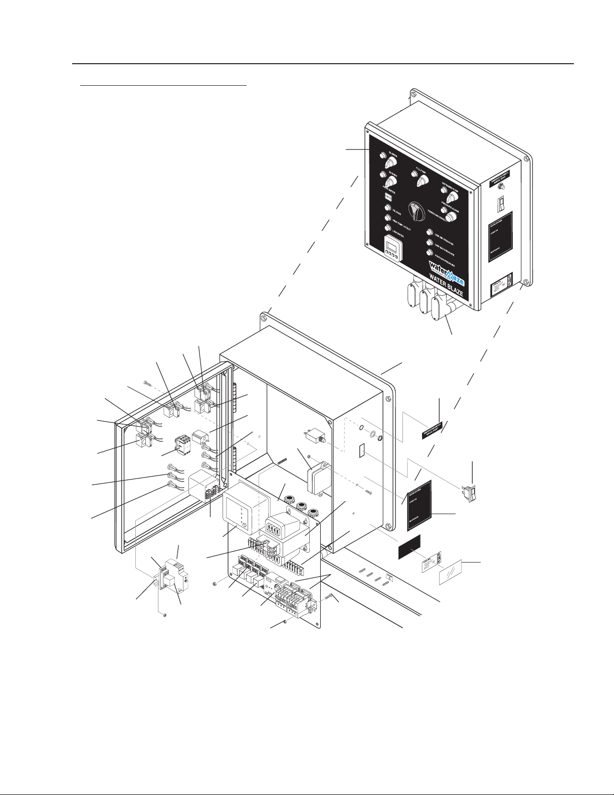
WATERMAZE SERIES OPERATOR’S MANUAL
33
WB • 8.913-984.0-N
8
1
0
1
2
1
4
1
6
0
2
4
6
WB-CONTROL PANEL
EXPLODED VIEW
15
14
16
18
20
19
21
12
8
9
7
6
10
2
1
5
3
11, 37, 38
23
27
26
22
24
17
4
10
29
32
25
30
31
33
9
19
20
21
13
89139840-17

34
WATERMAZE SERIES OPERATOR’S MANUAL
WB • 8.913-984.0-N
ITEM PART NO. DESCRIPTION QTY
1 8.716-280.0 Box, Plastic, 18" x 16" x 9-1/4"
w/Lid (WB-50) 1
8.716-416.0 Electrical Box
(WB-120) 1
8.716-415.0 Electrical Box Mounting Feet
(WB-120) 1
2 8.913-105.0 Stand Off, Control Box
(WB-50)
1
8.913-117.0 Stand Off, Control Box
(WB-120) 1
3 8.940-231.0 Label, WB-50 Control Panel 1
8.940-230.0 Label, WB-120 Control Panel 1
4 9.802-460.0 Fuse, Paper, Buss, FNM8,
250V Midget 70 1
8.716-180.0 Fuse KTK-R4, 600V Midget 2
5 8.718-175.0 Controller, UV-Purge 1
8.718-176.0 Controller, UV-Purge, Base 1
6 9.802-493.0 Block, Terminal, 16 Pole 1
9.802-494.0 ▲ Bar, Jumper 5
7 9.802-550.0 Transformer, Micron, 240/460 -
120/240, .500 KVA 1
8.716-873.0 Transformer, Micron, 208-115V,
.500 KVA (208 Volt Machines) 1
8 8.724-268.0 Contactor, 25 Amp
(WB-120A) 3
(WB-50A) 2
9 9.802-467.0 Base, Relay, Idec
(WB-50A) 5
(WB-120A) 6
10 9.802-468.0 Relay, 120V, Idec
(WB-50A) 5
(WB-120A) 6
ITEM PART NO. DESCRIPTION QTY
11 8.716-330.0 Box, Conduit, 1", 90°
(WB-50) 3
(WB-120) 4
8.716-331.0 Box, Conduit Cover
(WB-50) 3
(WB-120) 4
8.716-333.0 Gasket, Box, Conduit
(WB-50) 3
(WB-120) 4
12 8.716-236.0 Timer, Red Lion 1
13 9.802-283.0 Hour Meter
(Qty 1- WB-50; Qty 2 - WB-120)
14 8.754-210.0 Switch, Disconnect 1
15 9.802-455.0 Light, Indicator Green, 125V 5
16 8.716-408.0 Light, Amber, 125V 5
17 8.716-409.0 Light, Blue, 125V 1
18 8.751-910.0 Switch, CH, 2 Pos, ON/OFF
(WB-50) 2
(WB-120) 3
19 8.751-911.0 Switch, CH, 3 Pos, ON/OFF/ON
(WB-50) 2
(WB-120) 3
20 8.751-912.0 Block, Contact, CH, N/C
(WB-50) 2
(WB-120) 1
21 8.751-913.0 Block, Contact, CH, N/O
(WB-50) 5
(WB-120) 16
22 8.716-051.0 Switch, Curvette,
RGSCC211BBA, 2P, 120/230V 1
23 8.754-117.0 Hi Limit Control, 230F 1
24 8.900-536.0 Label, Manual Reset Temp.,
Switch 1
WB-CONTROL PANEL
EXPLODED VIEW PARTS LIST

WATERMAZE SERIES OPERATOR’S MANUAL
35
WB • 8.913-984.0-N
ITEM PART NO. DESCRIPTION QTY
25 8.716-091.0 Switch, Momentary Push, 100S
Use w/2-3020 1
26 8.940-237.0 Label, Evaporator Instruction 1
27 9.800-034.0 Label, Clear Lexan,
2-1/4" x 4-1/2" 1
28 9.800-040.0 ▲ Label, Ground 1
29 9.802-457.0 Din Rail 2" 1
30 9.802-759.0 Screw, 10/32" x 1/2" 8
31 9.802-696.0 Nut, 10/32" Keps 12
32 8.751-306.0 Timer, Multi-Function 1
33 8.716-253.0 Timer, 24 Hour Pin 1
34 8.716-080.0 ▲ Handle, Switch, Disconnect 1
35 8.753-352.0 ▲ Duct, Wire 2"Gray w/cover
(WB-120) 2.5
(WB-50) 8
36 8.753-351.0 ▲ Duct, Wire 1"Gray w/cover
(WB-120) 8.5
(WB-50) 6.5
37 8.716-010.0 Conduit, Metal 1" EMT
(WB-50) 1.5 ft.
(WB-120) 2 ft.
38 8.716-580.0 Connector, Metal, 1" EMT
(WB-50) 3
(WB-120) 4
▲ Not Shown
WB-CONTROL PANEL
EXPLODED VIEW PARTS LIST CONTINUED
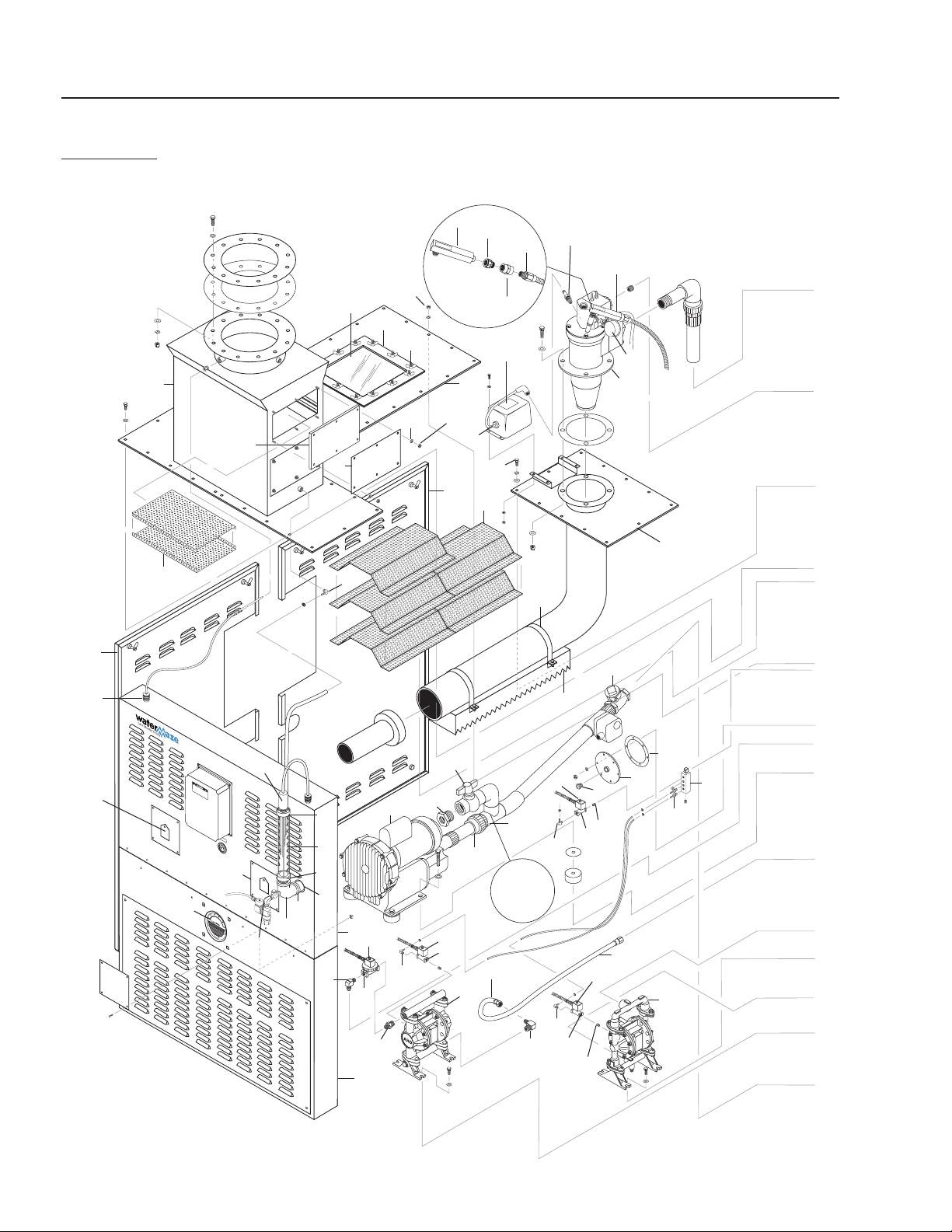
36
WATERMAZE SERIES OPERATOR’S MANUAL
WB • 8.913-984.0-N
WB-120A
EXPLODED VIEW LEFT SIDE
For
Detail See
Air Line
Assy.
Illus.
2
13
24
25
71
68
64
69
65
3
27
13
25
24
112
109
10
116
123
117
26
57
7
6
124
29
92
93
20
24
68
90
96
17
18
19
13
25
41
35
75
134
1
32
31
34
40
36
23
16
76
15
97
95
78
79
77
14
8
94
82
5
4
101
80
54
70
11
43
125
41
131
132
133
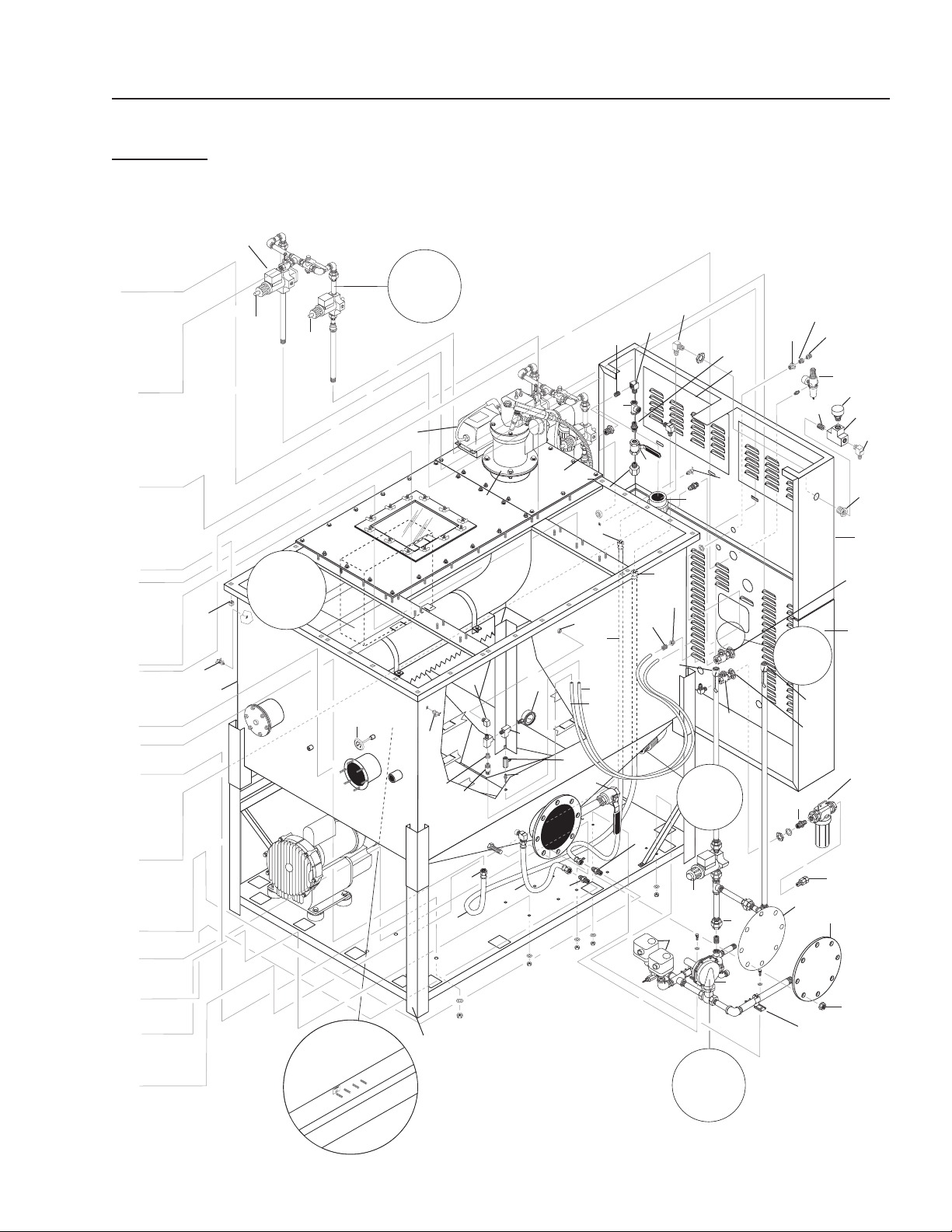
WATERMAZE SERIES OPERATOR’S MANUAL
37
WB • 8.913-984.0-N
127, 128,
129, 130
89139840-23
WB-120A
EXPLODED VIEW RIGHT SIDE
22
100
66
101
65
67
37
55
45
30
110
120
105
98
126
43
90
89
99
12
For
Detail See
Control
Panel
Illus.
To
Defoamer
Pump
9
21
74
119
126
For
Detail
See Gas
Plumbing
Assy
Illus.
For Detail
See Gas
Plumbing
Assy
Illus.
For Detail
See Air
Line Assy
Illus.
46
47
102
114
84
72
85
83
86
42
121
33
66
52
114
29
61
73
115
72
41
128
122
59
65
64
87
88
49
60,61
91
62
63
112
38,39
Reversed
View
58
103
48
126
104
113
56
56
56

38
WATERMAZE SERIES OPERATOR’S MANUAL
WB • 8.913-984.0-N
WB-120A
EXPLODED VIEW PARTS LIST
ITEM PART NO. DESCRIPTION QTY
1 8.913-019.0 Baffle, Screen 12
2 8.913-055.0 Panel, Bottom Front 1
3 8.913-054.0 Panel, Control End 1
4 8.716-300.0 Sensor, Capacitance, 3 Point 1
8.707-383.0 Gasket, Sight Glass Tube 2
8.706-757.0 Tube, Sight Glass 1
8.900-583.0 Label, Level Control 1
5 8.719-976.0 Body, Sight Glass, Upper,
Brass 1
8.719-977.0 Body,
Sight Glass, Upper, 304L
1
6 8.719-972.0 Body, Sight Glass, Lower,
Brass 1
8.719-973.0 Body, Sight Glass, Lower,
304L 1
7 8.719-974.0 Rod, Sight Tube, Brass,
1/4" x 12-1/2" 3
8 8.716-571.0 Strain Relief, 1/2" LQ Tite 3
9 8.712-158.0 Gauge, Thermometer 1
8.706-805.0 Nipple, 1/4" x 2-1/2", SCH 40
AL6XN (AL6XN Option) 1
8.706-814.0 Coupler, 1/4" AL6XN
(AL6XN Option) 1
8.706-806.0 ▲ Nipple, 1/4" x 2-1/2", 316L 1
8.706-813.0 ▲ Coupling, 1/4" Hex, 316L 1
10 8.913-025.0 Plate, Observation 2
11 8.913-010.0 Cover, View Port 2
9.800-028.0 ▲ Label, Pilot Light Hose 2
9.802-130.0 Elbow, 90°, 1/2" JIC x 1/4" 2
9.802-129.0 Elbow, 90°, 1/2" JIC x 3/8" 4
12 8.706-827.0 Elbow, Street, 1/4" 2
13 8.706-958.0 Hose Barb, 90°, 1/4" Barb
x 1/4" Pipe 3
14 8.913-052.0 Demister Box, WB-120, 316L 1
8.913-053.0 Demister Box, WB-120,
AL-6XN 1
8.707-405.0 Gasket, 12" Flange Exhaust
(WB-120) 1
15 8.913-015.0 Lid Center Plate, 316L 2
8.913-016.0 Lid Center Plate, AL-6XN 2
8.913-017.0 Lid Center Plate 1
16 8.912-972.0 Bezel, All 2
17 8.913-027.0 Cover Plate with Viewer 2
18 8.707-397.0 Gasket 2
ITEM PART NO. DESCRIPTION QTY
19 8.718-201.0 Glass, Site, Observation 2
20 8.715-190.0 Blower, Regenerative, 2.5 HP 2
9.802-066.0 ▲ Pad, Soft Rubber 8
9.802-819.0 ▲ Washer, 7/16" x 2-1/2" 8
8.709-083.0 ▲ Clamp, 3-1/2" SS, Band 1
21 8.913-066.0 Tank Assembly, WB-120, 316L 1
8.913-067.0 Tank Assembly, WB-120,
AL-6XN 1
8.707-386.0 ▲ Gasket, Evaporator Tank 1
22 8.913-060.0 Base, Assy 1
8.913-064.0 ▲ Raceway, Electrical 1
8.913-065.0 ▲ Raceway, Cover 1
23 8.706-758.0 Cover, Tempered Glass 2
8.707-382.0 ▲ Gasket, Bezel, All 4
24 8.716-691.0 Valve, Solenoid, 120V 3
25 9.802-533.0 Solenoid, Coil, 120V 3
26 8.716-689.0 Valve, Solenoid, 120V 1
27 8.716-690.0 Solenoid, Coil, 120V 1
28 8.706-475.0 Union, CPVC 80, 1-1/4" 2
29 8.706-474.0 Union, CPVC 80, 2" 4
30 8.717-748.0 Regulator, Rockwell, 3/4" 2
8.718-172.0 ▲ Orifice, Regulator, 1/2", LP 2
8.718-173.0 ▲ Orifice, Regulator, 5/8", NG 2
31 8.912-005.0 Burner, Sparger Tube
Assy 316L 2
8.912-006.0 Burner, Sparger Tube
Assy, AL-6XN 2
32 8.912-008.0 Distributor, Air, 316L 2
8.912-009.0 Distributor, Air, AL-6XN 2
33 8.906-087.0 Single, Ignition Wire 2
34 8.912-014.0 Bracket, WB Distributor
Mnt. 316L 4
8.912-015.0 Bracket, WB Distributor Mnt.
Ring, AL-6XN 4
9.802-724.0 ▲ Bolt, 3/8" x 1-1/2" HH, NC,
316L 8
9.802-808.0 ▲ Washer, 3/8" SS Flat 8
8.719-024.0 ▲ Washer, 3/8" SS Lock 8
8.719-089.0 ▲ Nut, 3/8" Hex, NC, 316L 8
35 8.718-177.0 Transformer, Ignition, 120V, All 2
36 8.718-185.0 Ignition Plug, 16946-5 Eclipse 2
▲ Not Shown

WATERMAZE SERIES OPERATOR’S MANUAL
39
WB • 8.913-984.0-N
WB-120A
EXPLODED VIEW PARTS LIST (CONT.)
ITEM PART NO. DESCRIPTION QTY
37 8.718-182.0 Valve, Gas Solenoid, 3/4" 2
38 8.716-321.0 ▲ Box, Junction, 3 Hole, 1/2" 3
39 9.802-483.0 ▲ Cover Plate, Junction Box,
2" x 4" 3
8.716-327.0 ▲ Box, Junction, 4" x 4",
5 Hole, 1/2" 1
8.716-329.0 ▲ Cover Plate, Junction Box,
4" x 4" 1
8.716-142.0 ▲ Switch, Float, N/O 1
40 8.718-159.0 Burner, Eclipse 2
41 8.718-174.0 Scanner, UV, All 2
42 8.718-166.0 Tube, Combustion 2
8.718-187.0 ▲ Gasket, Burner Eclipse, 7" 6
8.913-014.0 ▲ Gasket, Burner Eclipse, 7" 2
43 8.712-155.0 Gauge, Pressure, 0-10 psi 2
44 8.706-334.0 Union, 1/2" Black Pipe 2
45 9.802-049.0 Union, 3/4" Black Pipe 10
46 8.718-181.0 Valve, Gas Solenoid, 3/4",
MVDLE 2
47 8.718-180.0 Valve, 1/2" Gas Solenoid
MVDLE (Soft Start) 2
48 8.718-167.0 Orifice, Metering, 3/4",
SBO-D-7, NG 2
8.718-169.0 Orifice, Metering, 3/4",
SBO-C-3, LP 2
49 8.718-171.0 Orifice, Metering, 3/4",
SBO-A-1, (Soft Start) 2
50 8.718-170.0 ▲ Orifice, Metering, 2",
SBO-677 2
52 8.912-989.0 Panel, Valve Access 2
53 8.718-162.0 ▲ Valve, Butterfly, 2" 2
54 8.707-239.0 Valve, Swing Check, Brass, 2" 2
55 8.718-179.0 Switch, Gas & Air Pressure 6
56 8.712-172.0 Switch, Thermostat 4
57 9.802-131.0 Elbow, 1/2" JIC x 1/2", 90° 2
58 8.707-399.0 Gasket, Cleanout, Blind 1
59 8.913-057.0 Panel, Burner End (Top) 1
8.913-058.0 ▲ Panel, Burner End (Bottom) 1
60 8.707-000.0 Connector, Anchor, 1/2" 2
61 9.802-146.0 Swivel, 1/2" MP x 3/4" GHF 2
62 8.706-970.0 Swivel, 3/4" Fem HS x 3/4"
Fem 1
ITEM PART NO. DESCRIPTION QTY
63 8.709-179.0 Filter, 3/4" x 20 Mesh 1
64 9.802-152.0 Swivel, Push-on, 3/4" JIC Fem 4
65 9.802-261.0 Hose, Push-on, 3/4" 8 ft.
66 9.802-151.0 Swivel,
Push-on,
1/2" JIC Fem
10
67 9.802-259.0 Hose, Push-on, 1/2" 17 ft.
68 8.706-777.0 Nipple, Close, 1/4" 5
69 9.802-132.0 Elbow, 3/4" JIC x 1/2" 1
70 8.715-278.0 1/2" Air Diaphragm Pump,
Polypro 1
71 8.715-279.0 1/2" Air Diaphragm Pump, SS 1
72 9.803-557.0 Elbow, 90°, 3/4" JIC x 3/4" 2
73 8.707-210.0 Valve, 1/2" Ball, 316 SS 1
74 9.802-792.0 Nut, Cage, 3/8" x 12 Gauge 40
75 9.802-721.0 Bolt, 3/8" x 1" S/S NCHH,
316 SS 40
76 8.719-089.0 Nut, 3/8" Hex, NC, 316L 32
77 8.913-028.0 Demister, Door 2
78 9.804-573.0 Nut, 1/4", SS NC 12
79 8.718-568.0 Washer, 1/4", Flat, SS,
Sealing Rub 12
80 8.707-391.0 Gasket, Demister Box Door 2
82 8.913-063.0 Screen, Demister 4
83 8.706-483.0 Bulkhead, 3" FT x FT 1
84 8.706-799.0 Nipple, 3/4" PVC, Close 2
85 8.706-846.0 Tee, 3/4" Female, Pipe 2
86 8.707-243.0 Valve, Vacuum Relief 1
87 8.707-232.0 Valve, Swing Check, Brass,
3/4" 1
88 9.802-052.0 Bulkhead, 3/4" Poly Pro 1
89 8.749-860.0 Check Valve, PVC
1/8" MP 1
90 8.706-941.0 Hose Barb 1/4" x MPT 1/4" 4
91 9.802-254.0 Hose, 1/4", Push-on 15 ft.
92 8.706-435.0 Tee, 2" S x S 1
93 8.707-361.0 Valve, 1-1/2" S x S 1
94 8.912-984.0 Door Panel, Right Side 1
95 8.912-985.0 Door Panel, Left Side 1
8.912-981.0 ▲ Door Panel 2
96 8.715-191.0 Manifold, Air 1
97 8.718-906.0 Nut, 3/8" Wing, NC, SS 18
98 8.706-858.0 Tee, 1/4" Street 4
▲ Not Shown

40
WATERMAZE SERIES OPERATOR’S MANUAL
WB • 8.913-984.0-N
WB-120A
EXPLODED VIEW PARTS LIST (CONT.)
ITEM PART NO. DESCRIPTION QTY
99 8.707-341.0 Valve, In-line Metering 2
100 8.706-898.0 Nipple, 3/4" JIC x 1/2" MPT,
316L 1
101 8.706-900.0 Nipple, 3/4" JIC x 3/4" MPT,
316L 1
102 8.718-178.0 Switch, Proof of Closure 2
103 8.711-737.0 Tubing, 1/8" ID, Norprene 5 ft.
104 8.749-993.0 Fitting, Compression,
1/4" x 1/8" MP 2
105 8.707-227.0 Valve Ball, 1-1/2" 316L 1
106 8.706-857.0 ▲ Tee, 1/8" Street 1
107 8.706-940.0 Hose Barb, 1/4" Barb x
1/8" Pipe 1
108 8.706-955.0 ▲ Hose Barb, 1/4" Barb x
1/8" Pipe, 90° 1
109 8.718-200.0 ▲ Switch/Gauge,
Capsu-Photohelic Pressure 1
110 8.719-969.0 Cover, Clean Out Port, 316L 1
8.707-399.0 Gasket, Flange, Cleanout 1
111 8.706-832.0 Elbow, 3/4" Street 1
112 8.706-881.0 Nipple, 3/4" Pipe x 1/2" Pipe 2
113 8.706-999.0 Connector, 1/4" Anchor 1
114 8.706-790.0 Nipple, 1/2" Close 2
115 8.706-844.0 Tee, 1/2" Female Pipe 1
116 8.707-145.0 Nipple, 1-1/2" x 4" 316L 1
117 8.913-074.0 Elbow, 1-1/2", 316L 1
8.913-076.0 Elbow, 1-1/2", AL-6XN 1
ITEM PART NO. DESCRIPTION QTY
118 8.919-139.0 ▲ Pump, Peristaltic,
8-45 gpd, Sekokem 1
8.718-941.0 ▲ Screw, #10 x 5/8", Tek 2
8.906-084.0 ▲ Water Maze Set Up Kit 1
8.903-719.0 ▲ Tool Kit, Complete, Evap. 1
8.719-138.0 ▲ Defoamer,
WATER MAZE 5600 1 gal.
119 8.707-331.0 Regulator, Air w/ Filter,
1/4" Gauge 1
120 8.718-894.0 Nut, 7/8", SS 8
8.718-998.0 Washer, 7/8", Flat 8
8.719-026.0 Washer, 7/8", Lock 8
121 8.718-160.0 Visual Indicator 2
122 8.706-806.0 ▲ Nipple, 1/4" x 2-1/2",
316L 2
8.706-165.0 ▲ Elbow, 1/4", 45°, 316L 2
8.711-453.0 ▲ Nozzle Only, 4020S 2
123 8.706-051.0 ▲ Nipple, 1/2", Close 1
124 9.802-146.0 Swivel, 1/2" MP x 3/4" GHF
w/Strainer 1
125 8.706-406.0 Bushing, 1-1/2" x 1/2"
SPG x FT PVC80
Spears Only 2
126 8.706-910.0 Bushing, 1/4" x 1/8"
Pipe 3
127 8.913-046.0 Channel, Kindorf 4.5',
WB-15/25/50 1
128 8.924-659.0 Channel, Kindorf,
1-1/2"x1-1/2"x4.5" 2
129 8.731-149.0 Clamp, 3/4' Kindorf, C105-3/4 2
130 8.719-100.0 Clamp, Kindorf, 1-1/2' 1
131 8.716-572.0 Connector, Strain Relief,
TB 2522 1
132 8.706-141.0 Coupling, 1/2" Steel Pipe 1
133 8.716-547.0 Connector, 1/2" L/T,
Straight, Black 1
134 9.804-615.0 Cover, Battery Terminal, Red 2
▲ Not Shown
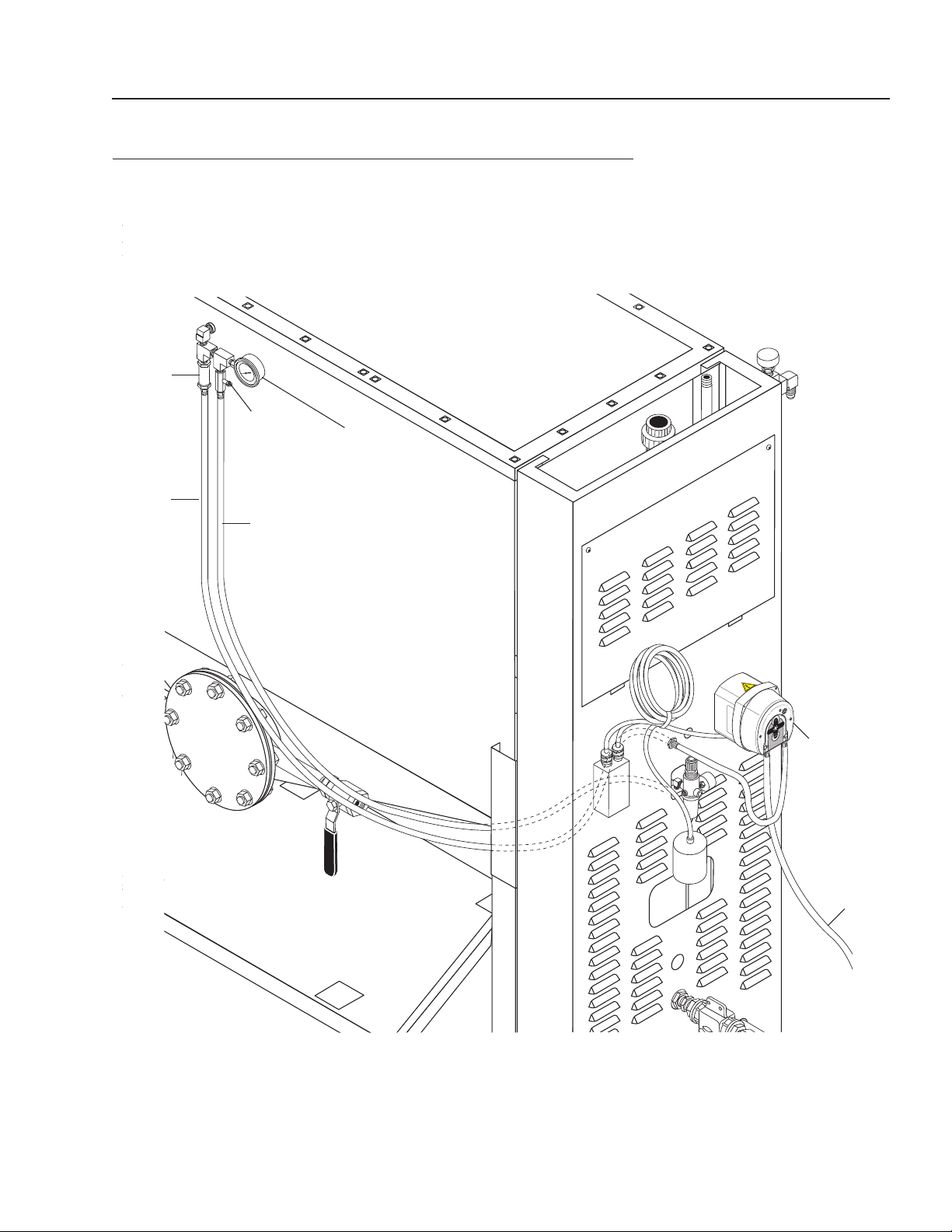
WATERMAZE SERIES OPERATOR’S MANUAL
41
WB • 8.913-984.0-N
Metering
Valve
0 - 10 PSI
Gauge
1/8"
Norprene
Chemical
Line
Air Line
Metering
Pump
1/8" PE
Chemical
Tube
Check
Valve
WATER MAZE WITH ANTI-FOAM METERING PUMP
Figure 11
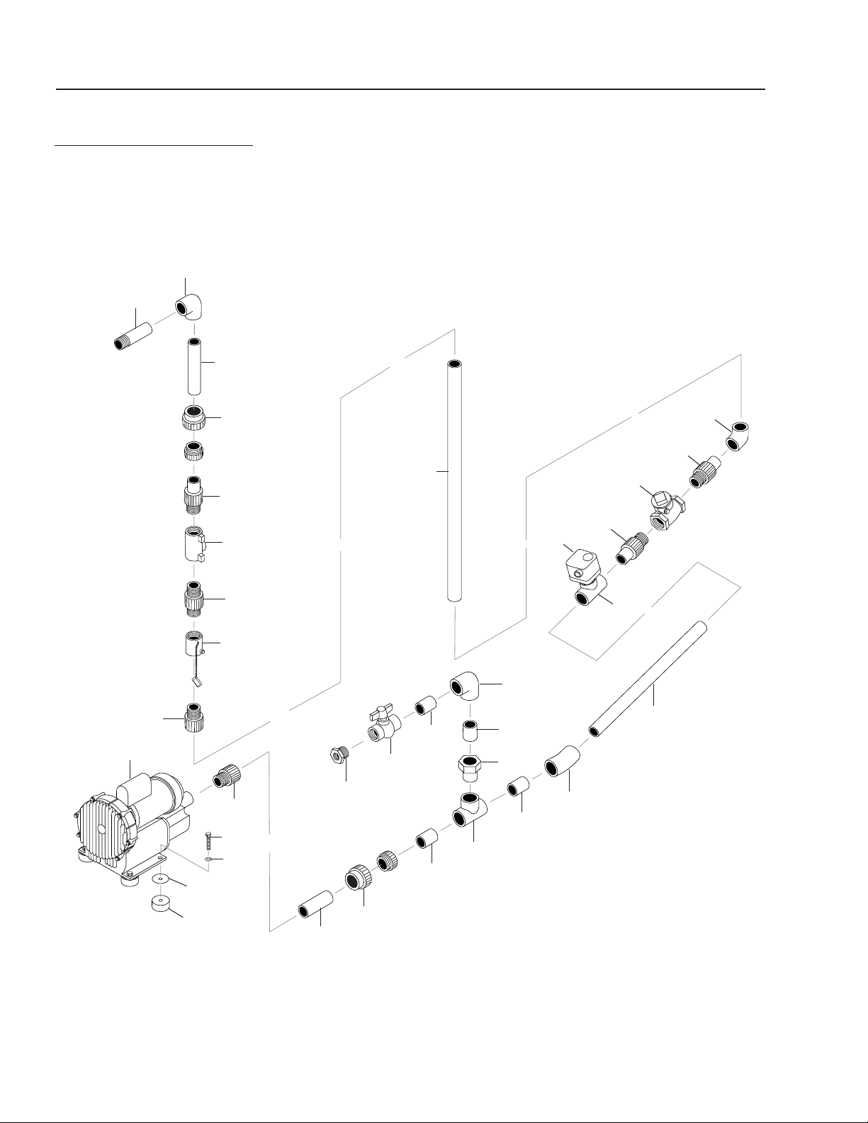
42
WATERMAZE SERIES OPERATOR’S MANUAL
WB • 8.913-984.0-N
AIR LINE ASSEMBLY
WB-50/120 EXPLODED VIEW
1
10
18
7
18
6
2
3
4
5
16
6
19
20
9
18
8
20
11
18
15
6
6
7
18
12
17
18
8
6
13
6
9
18
14

WATERMAZE SERIES OPERATOR’S MANUAL
43
WB • 8.913-984.0-N
AIR LINE ASSEMBLY PARTS LIST
WB-50/120
ITEM PART NO. DESCRIPTION QTY
1 8.715-190.0 Blower, Regenerative, 2.5,
120/240V, R6125-2 1
2 9.802-066.0 Pad, Soft Rubber, 50 Duro 4
3 9.802-819.0 Washer, 7/16" x 2-1/2", Zinc,
PG Foot 4
4 8.725-394.0 Washer, 3/8", SAE, Flat 8
5 9.802-730.0 Bolt, 3/8" x 2-1/2" GR 5, Zinc 4
6 8.706-452.0 Adapter, 2" Slip x MT,
CPVC 80 6
7 8.706-474.0 Union, 2" Slip, CPVC 80, GF 2
8 8.706-435.0 Tee, 2" Slip x Slip x Slip,
CPVC 80 2
9 8.706-380.0 Elbow, 2" S x S, XPVC 80,
45° 2
10 8.706-406.0 Bushing, 1-1/2" x 1/2"
SPG x FT,
PVC 80, Spears Only 1
11 8.707-361.0 Valve, 1-1/2" S, PVC 80, S x S,
Molded In Place 1
12 8.706-383.0 Elbow, 2" S x S, CPVC 80,
90° 1
13 8.707-239.0 Valve, 2" Brass, IB904,
Swing Check 1
14 8.706-413.0 Bushing, 2" x 1-1/2" Slip,
PVC 80 1
15 8.718-162.0 Valve, Butterfly, 2" 1
16 8.718-170.0 Orifice, 2" SBO-677,
Metering 1
18 8.706-584.0 Pipe, 2", CPVC 80 6.5 ft.
17 8.718-179.0 Switch, Gas & Air Pressure,
GAO-A4-4-6 3
19 8.706-374.0 Elbow, 1-1/2" S x S, PVC 80,
90° 1
20 8.706-367.0 Pipe, 1.5", PVC 80, .5 ft.
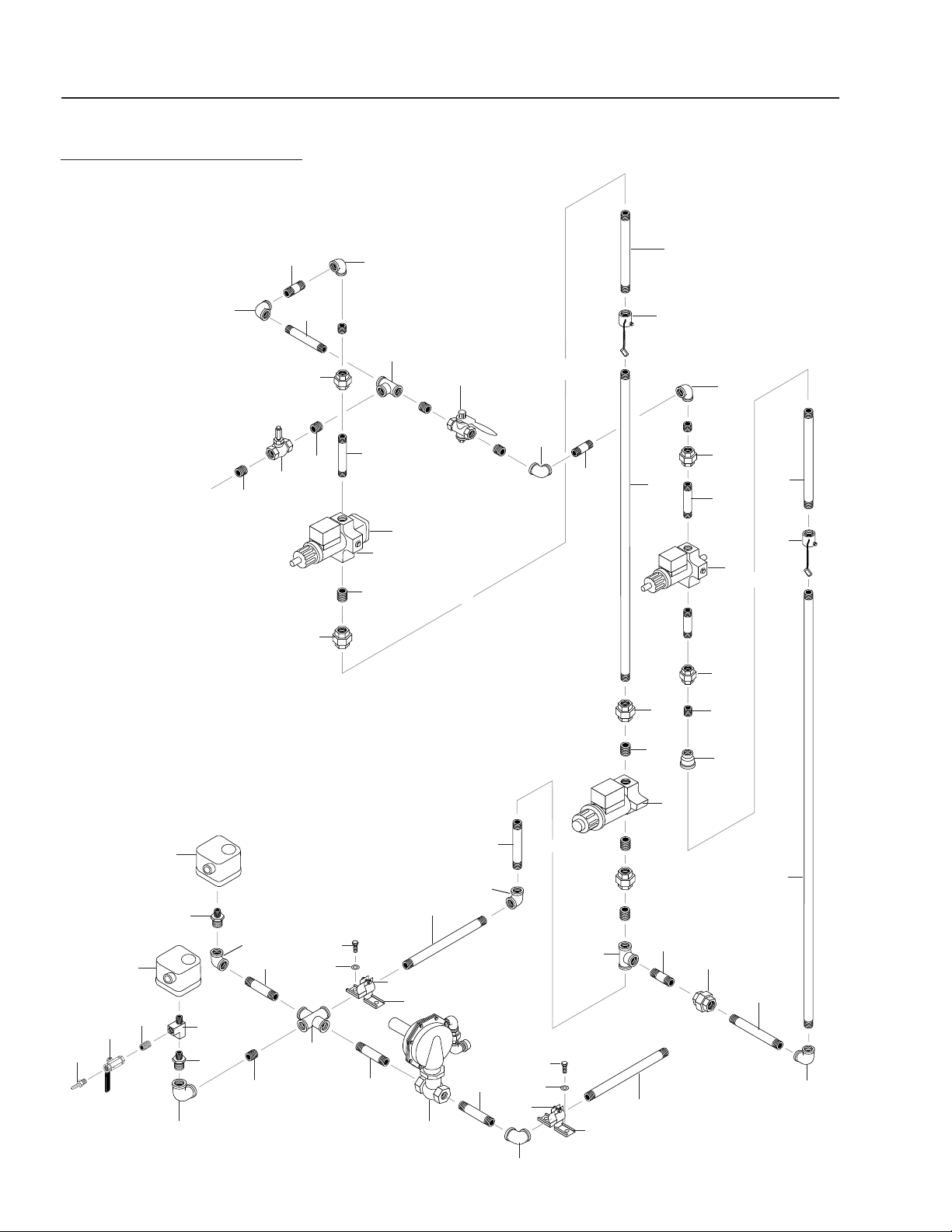
44
WATERMAZE SERIES OPERATOR’S MANUAL
WB • 8.913-984.0-N
GAS TRAIN ASSEMBLY
WB-50 EXPLODED VIEW
9
37
29
31
25
8
36
36
32
8
39
37
27
9
29
37
33
34
20
33
29
26
23
38
12
16
11
29
28
27
6, 42
37
14
15
15
10
13
12
11
16
8
15
30
37
8
17
18
19
41
15
40
10
4
7
8
5
1
2
3
8
7
5
22
21
35
34
24

WATERMAZE SERIES OPERATOR’S MANUAL
45
WB • 8.913-984.0-N
GAS TRAIN ASSEMBLY
WB-50 EXPLODED VIEW PARTS LIST
ITEM PART NO. DESCRIPTION QTY
1 8.706-941.0 Hose Barb, 1/4" Barb x
1/4" ML Pipe 11
2 9.802-178.0 Valve, Ball, 1/4" Female x
1/4" Female, UL Listed #12 2
3 8.706-777.0 Nipple, 1/4" Close,
P/N 3326-4 19
4 8.706-854.0 Tee, 1/4" Branch, Male 3
5 8.718-179.0 Switch, Gas & Air Pressure,
GAO-A4-4-6 6
6 8.717-748.0 Regulator, Rockwell, 3/4"
143-80-2-12-BW-8 1
7 8.706-923.0 Bushing, 3/4" x 1/4" Pipe 4
8 9.802-027.0 Elbow, 3/4", Black, 90° 6
9 9.802-025.0 Elbow, 1/2" Female, Black 4
10 8.913-046.0 Channel, Kindorf, 4.5" 2
11 9.802-721.0 Bolt, 3/8" x 1" HH/NC,
316 SS 54
12 9.802-808.0 Washer, 3/8", SS, Flat 120
13 8.731-149.0 Clamp, 3/4" Kindorf,
C105-3/4" 2
14 8.706-225.0 Cross, 3/4" Black Pipe FIPT 2
15 9.802-021.0 Nipple, 3/4" x 9", Black 4
16 9.802-971.0 Nipple, 1"NPT x 15,
SCH 40 Black 1
17 8.706-115.0 Nipple, 3/4" x 35" Black 2
18 9.803-561.0 Nipple, Black Pipe, 3/4" x 5" 6
19 8.718-171.0 Orifice, 3/4", SBO-A-1,
Metering 1
20 8.706-114.0 Nipple, 3/4" x 25", Black 2
21 8.718-167.0 Orifice, 3/4" SBO-D-7,
Metering 1
8.718-169.0 Orifice, 3/4" SBO-C-3,
Metering (LP Option) 1
22 8.706-110.0 Nipple, 3/4" x 8" STD, Black 3
23 8.718-182.0 Valve, 3/4", Eclipse, 46040-3
MVD, Gas Solenoid 2
24 8.718-180.0 Valve, 1/2", Eclipse, 46030-2,
Gas Solenoid 2
ITEM PART NO. DESCRIPTION QTY
25 8.755-266.0 Valve, Flow, Gas 1/2", Adjustable
(WB-50) 1
(WB-120) 2
26 8.718-181.0 Valve, 3/4", Eclipse, 46030-3
MVDLE, Gas Solenoid 2
27 8.706-222.0 Tee, 3/4" Black Pipe 4
28 9.802-018.0 Nipple, 3/4" x 3", Black Pipe 2
29 9.802-049.0 Union, 3/4", Black Pipe 11
30 8.706-070.0 Reducer, 3/4" x 1/2", Bell,
Black 2
31 8.706-052.0 Nipple, 1/2" Close, Black 6
32 9.802-019.0 Nipple, 3/4" x 2", Black 3
33 8.706-334.0 Union, 1/2" Black 4
34 8.706-054.0 Nipple, 1/2" x 2-1/2" Black 6
35 8.718-178.0 Switch, Proof of Closure,
CP1400 2
36 8.706-056.0 Nipple, 1/2" x 6", Black 4
37 9.802-017.0 Nipple, 3/4" x Close, Black 23
38 8.706-108.0 Nipple, 3/4" x 3-1/2",
Black Pipe 2
39 8.718-165.0 Valve, Gas, Limiting 1
40 8.719-098.0 Clamp, Kindorf, C105-1" Pipe 1
41 9.802-028.0 Elbow, 1"x3/4", Reducing
90 DGR Black 1
42 8.718-173.0 Orifice, 5/8" Regulator 1
8.718-172.0 Orifice, 1/2" Regulator
(LP Option) 1
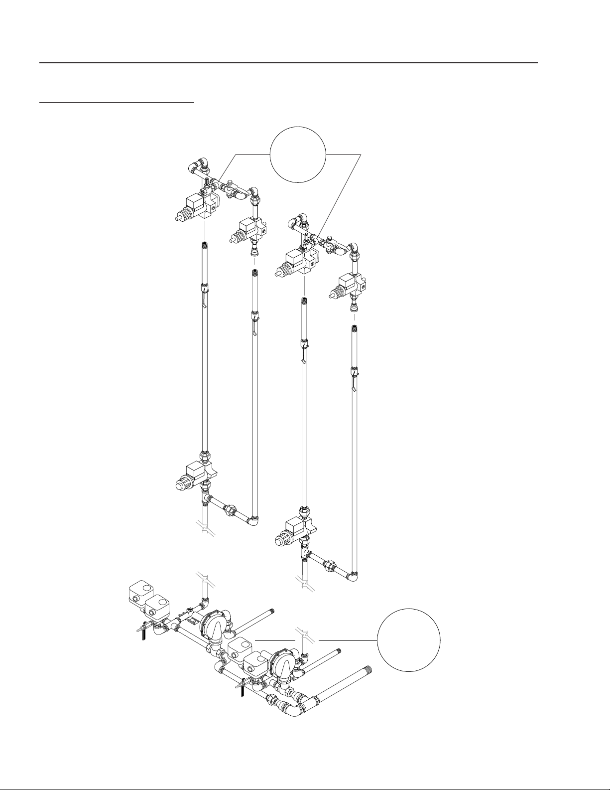
46
WATERMAZE SERIES OPERATOR’S MANUAL
WB • 8.913-984.0-N
GAS TRAIN ASSEMBLY
WB-120
For
Details See
WB-50 Gas
Train Assy
Illus.
For
Details
See WB-120
Gas Train Assy
Exploded
View
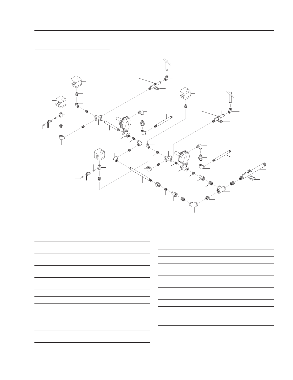
WATERMAZE SERIES OPERATOR’S MANUAL
47
WB • 8.913-984.0-N
GAS TRAIN ASSEMBLY
WB-120 EXPLODED VIEW
To Gas
Line
To Gas
Line
14
9
8
6
20
19
21
17
18
12
6
8
21
12
8
7
25
8
12
16
10
8
11
10
8
6
1
8
8
6
15
6
9
7
6
5
4
2
22
26, 27
23
23
24
24
4
3
4
5
6
1
6
13
8
7
18
12
19
8
6
20
21
17
6
ITEM PART NO. DESCRIPTION QTY
1 8.717-748.0 Regulator, 3/4" Rockwell,
143-80-2-12-BW-8 2
2 8.706-195.0 Elbow, 1-1/2" Female, Black,
90° 1
3 8.706-219.0 Tee, 1-1/2", Female, Pipe,
Black 1
4 8.706-014.0 Nipple, 1-1/2" Close,
Black Pipe 3
5 8.706-072.0 Reducer, 1-1/2" x 3/4", Bell
Black Pipe 2
6 9.802-017.0 Nipple, 3/4" x Close, Black 23
7 9.802-049.0 Union, 3/4", Black Pipe 11
8 9.802-027.0 Elbow, 3/4", Black, 90° 14
9 8.706-225.0 Cross, 3/4" Black Pipe FIPT 2
10 8.706-183.0 Elbow, 1", Street, Black, 90° 4
11 8.706-112.0 Nipple, 3/4" x 11" Std, Black 1
12 8.718-179.0 Switch, Gas & Air Pressure,
GAO-A4-4-6 6
ITEM PART NO. DESCRIPTION QTY
13 8.706-112.0 Nipple, 3/4" x 11" Black 1
14 8.706-110.0 Nipple, 3/4" x 8" STD, Black 3
15 9.802-021.0 Nipple, 3/4" x 9", Black 4
16 8.706-020.0 Nipple, 1" x 12-1/2", Black 1
17 8.706-854.0 Tee, 1/4" Branch, Male 3
18 8.706-777.0
Nipple, 1/4" Close,
P/N 3326-4 19
19 9.802-178.0 Valve, Ball, 1/4" Female x
1/4" Female, UL Listed #12 2
20 8.706-941.0 Hose Barb, 1/4" Barb x
1/4" ML Pipe 11
21 8.706-923.0 Bushing, 3/4" x 1/4" Pipe 4
22 8.706-116.0 Pipe, 1-1/2" x 17", Black 1
23 8.924-659.0 Channel, Kindorf,
1-1/2x1-1/2"x4.5" 2
24 8.731-149.0 Clamp, Kindorf 2
25 9.802-021.0 Nipple, 3/4" x 9" Black 1
26 8.913-046.0 Channel, Kindorf 4.5',
WB-15/25/50 1
27 8.719-100.0 Clamp, Kindorf, 1-1/2" 1
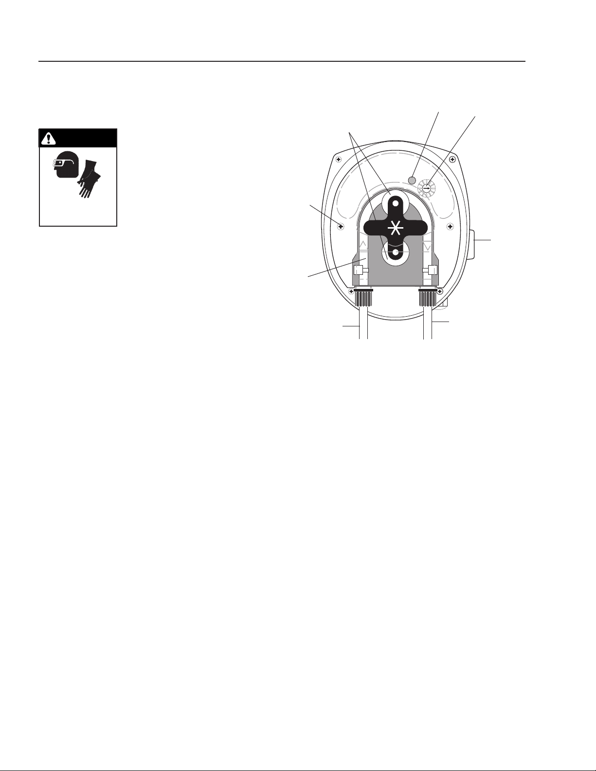
48
WATERMAZE SERIES OPERATOR’S MANUAL
WB • 8.913-984.0-N
REPLACING PUMP
HEAD TUBING:
WARNING: Wear protective
gloves, goggles, and other ad-
equate protection for the chemi-
cal hazard. Before replacing the
pump head, remove chemical
from tubing as follows. Remove
strainer from chemical tank then
run pump until all chemical is
removed from the tubing.
1. Remove the compression fittings from the tubing at
the pump head.
2. Pull the suction and discharge tubing from the pump
head.
3. Remove the front cover.
4. Rotate the pump rollers to a vertical position.
5. Lift the inlet fitting out of the housing.
6. Pull the tube out while rotating the pump rollers
clockwise.
7. Remove the outlet fitting.
8. Install the inlet fitting for the new tube assembly.
9. Press the tube into place in front of a roller while
rotating the roller assembly clockwise.
10. Install the outlet fitting.
11. Reconnect the suction and discharge lines.
12. Install the front cover.
CAUTION: DO NOT LOSE THE BEARING FROM THE
CENTER HOLE IN THE COVER PLATE.
WARNING
WEAR PROTECTIVE
GLOVES, GOGGLES
AND CLOTHING.
Figure 10
Indicator
Light
On-Off-Full
Speed
Switch
(right or
left side)
Cover
Screws
Squeeze
Tube
Speed
Adjusting
Screw w/
Indexing
Marks
Pump
Rollers
Discharge
Inlet
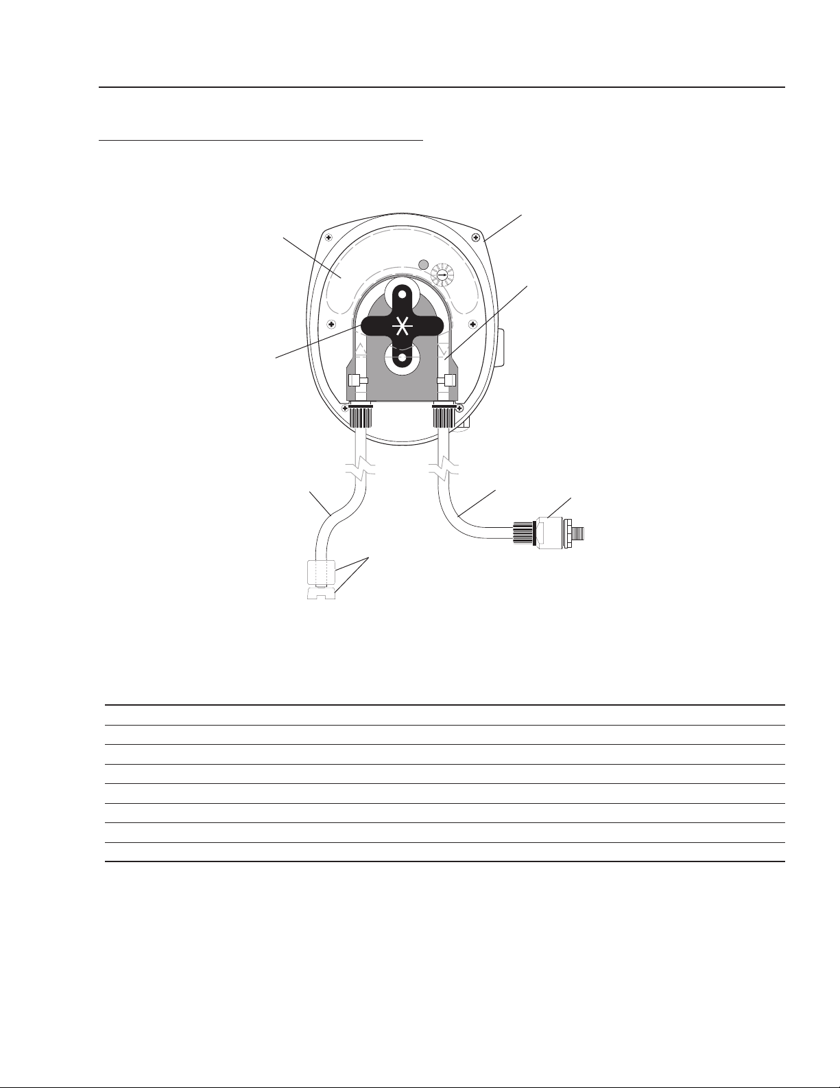
WATERMAZE SERIES OPERATOR’S MANUAL
49
WB • 8.913-984.0-N
METERING PUMP AND PARTS LIST
ITEM PART NO. DESCRIPTION QTY
1 8.919-139.0 Pump, Peristaltic, PR-7, 8-45 gpd, Sekokem 1
2 8.750-963.0 Tube, Squeeze, Sekokem, PR-7,* 8-45 gpd 1
3 8.749-860.0 Check Valve, PVC 1
4 8.749-857.0 Tubing, 1/4", PE, Black AR
5 8.749-863.0 Strainer, w/welght 1
6 8.711-737.0 Tubing, 1/8", ID, Norprene AR
7 8.751-801.0 Faceplate, PRS-1/PR-7 1
8 8.751-375.0 Roller Assembly, PR-7 1
* Alternative tubing materials are available
1
2
6
3
4
7
8
5
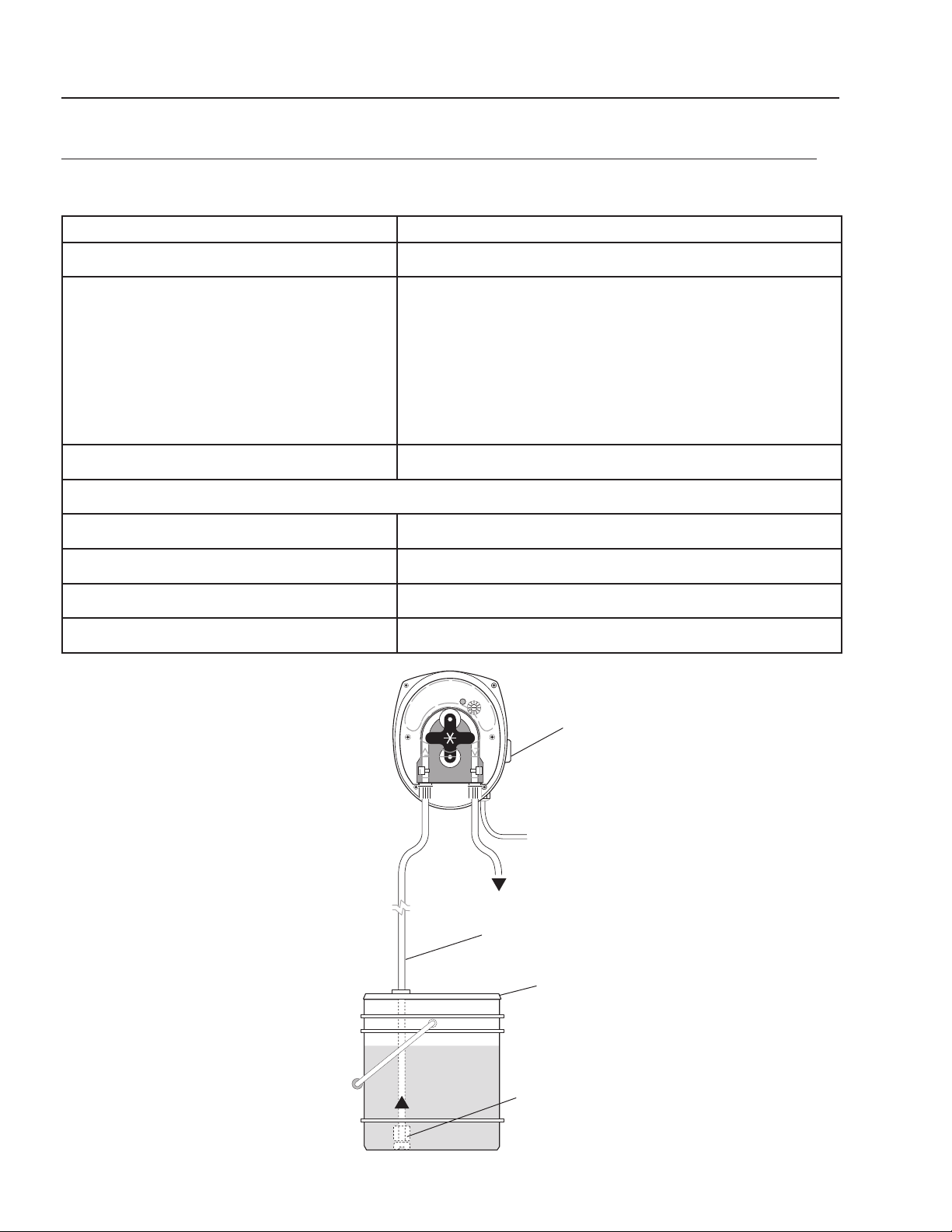
50
WATERMAZE SERIES OPERATOR’S MANUAL
WB • 8.913-984.0-N
SERIES VARIABLE SPEED PERISTALTIC METERING PUMP MODELS VSP 20
#5-2360 TECHNICAL INFORMATION
INSTALLATION DIAGRAM
Feed Rate
8 - 45 GPD (1-7 GPD pump available)
Dimensions
5" H x 4" W x 4 1/4" D
Standard Accessories Included
Tubing
Squeeze Tubing Assy. (Installed)
Check Valve, 1/8" MNPT
Strainer w/ Ceramic weight
Suction: 1/4", Polyethylene Tubing
Discharge: 1/8" ID, Norprene,Tubing
Electrical Rating
20-265V 50/60Hz
Materials:
Pump Head
Polycarbonate
Pump Head Tubing
Sekokem (other materials available)
Strainer and Injection Point Fitting
PVC
Maximum System Pressure
45 psi (maximum allowed at injection fitting)
Figure 11
Suction
Tubing
Power Card
Strainer
Chemical
Container
On/Off
Switch
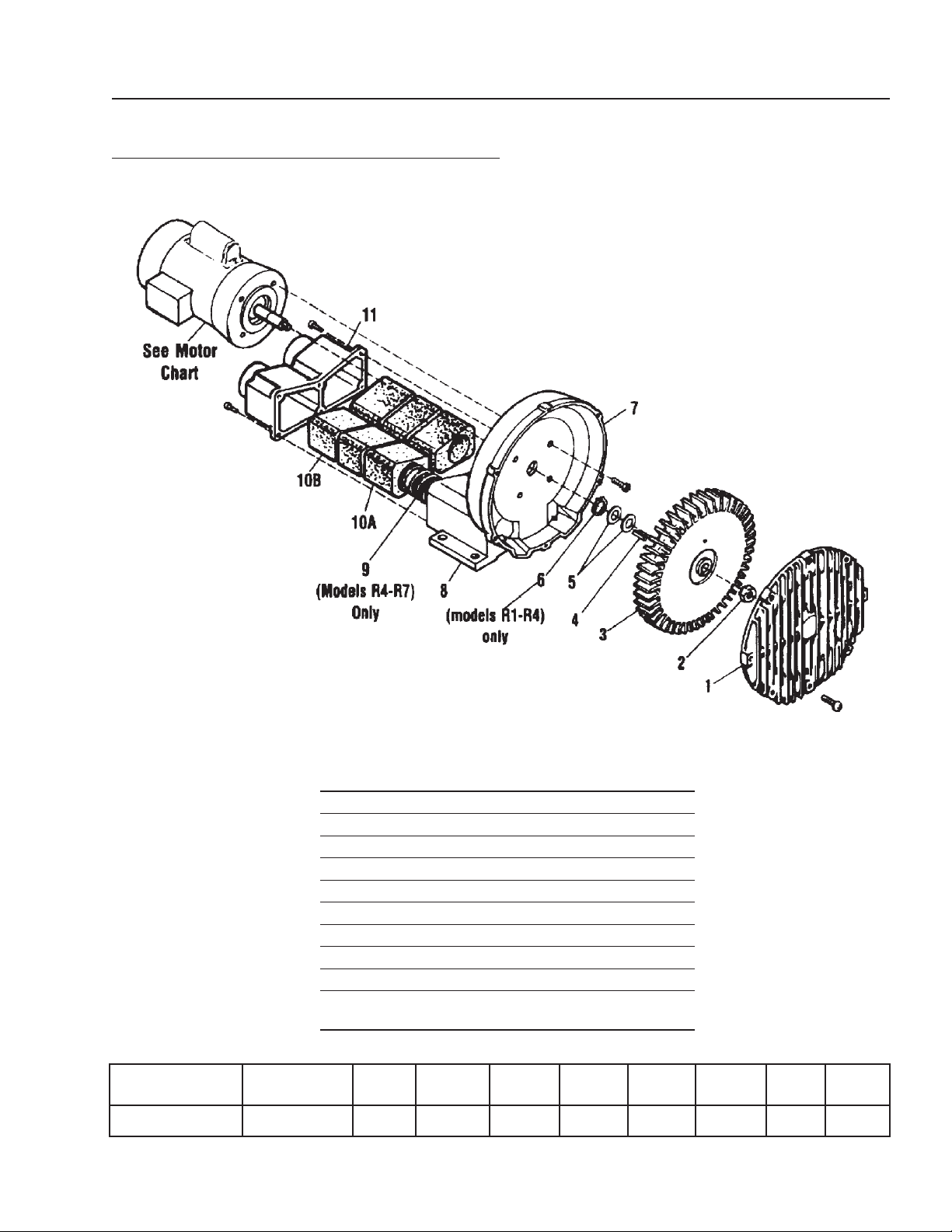
WATERMAZE SERIES OPERATOR’S MANUAL
51
WB • 8.913-984.0-N
WB-50/120 REGENERATIVE BLOWER
2.5 HP, 8.715-190.0
ITEM PART NO. DESCRIPTION QTY
1 15-AJ101FB Cover 1
2 15-BC181 Stop Nut 1
3 15-AJ102FR Impeller 1
4 15-AB136D Square Key 1
5 15-AJ109 Shim Spacer(s) 1
7 15-AJ103FQ Housing 1
8 15-AJ106FR Muffler Box 1
9 15-AJ113FQ Spring 1
10A 8.705-471.0 Foam 6
11 15-AJ106FR Muffler Extension/Adapter
Plate 1
Motor Specs Full Load
Amps
HP RPM H2O mbar cfm m3h lbs kg
115/208-230-60-1 23.6/12.9-11.8 2.5 3450 45 112 215 365 87 39.5
52
WATERMAZE SERIES OPERATOR’S MANUAL
WB • 8.913-984.0-N
BURNER
PROBLEM POSSIBLE CAUSE SOLUTION
FAILS TO LIGHT
Air is in gas line after initial
installation
Purge gas line. Repeat ignition
trial several times to purge line.
Ignition transformer malfunctions Check wiring and proper voltage for
transformer. Also clean and gap the spark
electrode. Replace if necessary.
Gas solenoid won’t open Faulty electrical circuit needs repair.
Not enough air pressure See TROUBLESHOOTING - Blower
Low or high gas pressure Check static pressure and regulate as needed.
Low water level in the evapora-
tion tank
Fill tank to indicated mark on sight glass.
Gas line valve closed Open valve on gas line.
MAIN GAS VALVE
OPENS, BUT BURNER
FAILS TO LIGHT
Air in gas line after initial instal-
lation
Purge gas line. Repeat ignition trial several
times to purge line.
BURNER IGNITES
BUT GOES OUT
AFTER 8 SECONDS
UV scanner failure Check electrical connection. Replace if necessary
Check flame signal light to verify if it is
illuminated.
Clean dirt or moisture from scanner.
BURNER SHUTS
DOWN DURING
NORMAL
OPERATIONS
UV scanner failure Check electrical connection. Replace if
necessary.
Loss of air pressure See TROUBLESHOOTING - Blower.
Loss of gas pressure Check gas line pressure and correct if necessary.
Sparger tube or air distributor
needs to be cleaned
Clean sparger tube and air distributor.
Not enough water Refill supply tank. Refill evaporator tank. Restart
evaporator.
Temperature too high Manual
reset thermostat shuts burner
down
Determine why overheating is occurring. Reset
manual reset switch.
BURNER BEHAVES
ERRATICALLY, DOES
NOT RESPOND
TO ADJUSTMENT
Burner internals loose, dirty or
burned out
Contact WATER MAZE dealer for repairs
or replacements.
VERIFLAME
INDICATOR LIGHTS
ACT ERRATICALLY
The ground is insufficient
Voltage is allowed through the
neutral wire
Connect a ground wire from the ground terminal
bolt to the neutral terminal.
VERIFLAME
INDICATOR LIGHT
GOES TO FLAME
FAILURE
High or low static gas pressure Readjust static gas pressure.
Pressure lock in high gas switch Bleed high gas pressure switch.
Faulty gas pressure switch Replace if necessary.
(Continued on next page)A
TROUBLESHOOTING

WATERMAZE SERIES OPERATOR’S MANUAL
53
WB • 8.913-984.0-N
BURNER
BLOWER
PROBLEM POSSIBLE CAUSE SOLUTION
(Burner Continued)
VERIFLAME
INDICATOR LIGHT
GOES TO AIR
FAILURE
Foaming Add defoamer.
Demister screens plugged Clean demister screens.
Sparger tube plugged Clean sparger tube.
Air distributor plugged Clean air distributor.
Faulty air pressure switch Replace if necessary.
BURNER BUMPS
UPON IGNITION
Gas solenoid valve opens too slowly Adjust gas solenoid valve so it opens
quicker.
PHOTOHELIC
SHUTS BURNER
OFF
Foaming or water in photohelic hose Add defoamer or drain photohelic hose.
PROBLEM POSSIBLE CAUSE SOLUTION
EXCESS VIBRATION
Impeller damaged or contaminated by
foreign material
Replace or clean impeller, install adequate
filtration.
ABNORMAL SOUND
Motor bearing failed, impeller rubbing
against cover or housing
Replace bearings, repair blower and check
clearances.
INCREASE IN SOUND
Foreign material or heat can destroy
muffler foam
Replace foam muffler elements and filter
foreign materials.
BLOWN FUSE
Electrical wiring problem Have a qualified person check that impeller
turns. Also check fuse, wiring diagram and
wiring.
MACHINE VERY HOT
Running at too high pressure or
vacuum
Install a relief valve and pressure or vacuum
gauge.
BLOWER WON’T
START
Blower control switch turned to auto-
matic and liquid level in holding tank
is low
Turn blower control switch to manual or fill
wastewater holding tank.
TROUBLESHOOTING
54
WATERMAZE SERIES OPERATOR’S MANUAL
WB • 8.913-984.0-N
AIR PUMP
PROBLEM POSSIBLE CAUSE SOLUTION
AIR PUMP
WON’T START
Long float, top micro switches not ener-
gized. Water too high
Keep evaporating or manually lower
the water level.
Air regulator setting adjusted too low Readjust air regulator to between 50
and 100 psi.
Air pump solenoid plugged Clean out.
No voltage to air pump solenoid coil Check wiring in electrical box. Re-
place parts as needed.
Bad air pump solenoid coil Replace solenoid coil.
WASTEWATER
DISCHARGING FROM
AIR PUMP EXHAUST
Check for diaphragm rupture If ruptured, replace.
Check for diaphragm nut Tighten nut.
AIR BUBBLES IN
DISCHARGE HOSE
Check connections of suction
plumbing
If loose, retighten.
Check band clamps on intake manifold If loose, retighten.
Check o-rings between intake manifold and
fluid caps
Replace o-rings if worn.
Check tightness of diaphragm nut Tighten nut.
AIR PUMP BLOWS AIR
OUT MAIN EXHAUST
WHEN STALLED ON
EITHER STROKE
Check U cups on spool in major valve Replace if needed.
Check valve plate and insert for wear Replace if needed.
Check sleeve and o-ring on diaphragm
connecting rod
Replace if needed.
Check o-rings on piston for wear Replace if needed.
LOW DISCHARGE
G.P.M.
Check air supply Adjust to between 50 and 100 psi.
Check for plugged discharge hose Unplug discharge hose.
For the pump to prime itself it must be
mounted in a vertical position so that the
balls will check by gravity
Level machine.
Check for pump cavitation - suction pipe
should be 1/2" minimum or larger if high
vicosity fluids are being pumped. Suction
hose must be noncollapsible type, capable
of pulling a high vacuum
Replace hoses if undersized.
Check all joints on intake manifolds and
suction connections These must be air tight
Tighten all joints and connections.
Check for sticking or improperly
seating valves
Clean check valves.
If pump cycles at a high rate or runs errati-
cally, check piston o-rings for wear
Replace o-rings if needed.
TROUBLESHOOTING

WATERMAZE SERIES OPERATOR’S MANUAL
55
WB • 8.913-984.0-N
SPECIFICATIONS
MODEL WB-50A WB-120A
EVAPORATION RATE GPH /LPH
60 (227) 120 (454)
FUEL USAGE BTU
570,956 1,146,912
FUEL SUPPLY
Natural or LP gas, 2 psig
1" NPT connection
1.5" NPT
VENT STACK IN / CM
10 (25) 12 (31)
TANK CAPACITY GAL / L
86 (326) 182 (689)
POWER SUPPLY
230V 1PH 230V 1PH
AMPS
11 22
LENGTH/WIDTH/
HEIGHT
IN / CM
75.5/32/81
(192/81/206)
80/55/81
(203/140/206)
NET WEIGHT LBS / KG
895 (407) 1690 (768)

56
WATERMAZE SERIES OPERATOR’S MANUAL
WB • 8.913-984.0-N
WATER MAZE SERVICE LOG
All entries will be recorded in "hours on the machine" at time of cleaning
UV
Scanner
Cleaned
Ignition
Plug
Inspected
Clean
(20) Mesh
Waste Water
Screen
Sludge
Removal
3 Point
Level
Rods
Sparger
Tube
Cleaned
Air
Distributor
Cleaned

WATERMAZE SERIES OPERATOR’S MANUAL
57
WB • #8.913-984.0-N
LIMITED NEW PRODUCT WARRANTY
WASH WATER / WATER TREATMENT SYSTEMS
WHAT THIS WARRANTY COVERS
All
WATER MAZE
water treatment systems are warranted by to the original purchaser to be free from defects in materials
and workmanship under normal use, for the periods specified below. This Limited Warranty, subject to the exclusions shown
below, is calculated from the date of the original purchase, and applies to the original components only. Any parts replaced
under this warranty will assume the remainder of the part’s warranty period. A 60 day grace period will be given for installa-
tion.
ONE YEAR PARTS AND 30 DAY LABOR WARRANTY:
All components excluding normal wear items as described below.
WARRANTY PROVIDED BY OTHER MANUFACTURERS:
Motors, which are warranted by their respective manufacturers, are serviced through these manufacturers’ local authorized
service centers.
WATER MAZE
cannot provide warranty on these items.
WHAT THIS WARRANTY DOES NOT COVER
This warranty does not cover the following items:
1. Normal wear items, such as seals, filters, gaskets, O-rings, packings, pistons, brushes, filtering media, ozone
bulbs, sensors, UV scanners, oil-skimmer belt, impedance sensor. Minor leaks covered first time on original start-
up only.
2. Damage or malfunctions resulting from accidents, abuse, modifications, alterations, incorrect installation, improper
servicing, failure to follow
manufacturer’s maintenance instructions, or use of the equipment beyond its stated
usage specifications as contained in the operator’s manual.
3. Damage due to freezing, sludge build-up, chemical deterioration (oxidation, chloride or fluoride corrosion), and
rust.
4. Damage to components from fluctuations in electrical or water supply.
5. Normal maintenance service, including adjustments.
6. Transportation to service center, field labor charges, or freight damage.
7. Consumables and water quality.
WHAT YOU MUST DO TO OBTAIN WARRANTY SERVICE
While not required for warranty service, we request that you register your
WATER MAZE
Product by returning the com-
pleted registration card. In order to obtain warranty service on items warranted by
WATER MAZE
, you must return the
product to your Authorized
WATER MAZE
Dealer, freight prepaid, with proof of purchase, within the applicable warranty
period. If the product is permanently installed, you must notify your Authorized
WATER MAZE
Dealer of the defect. Your
Authorized
WATER MAZE
Dealer will file a claim with
WATER MAZE
, who must subsequently verify the defect. In most
cases, the part must be returned to
WATER MAZE
freight prepaid with the claim. For warranty service on components
warranted by other manufacturer’s, your Authorized
WATER MAZE
Dealer can help you obtain warranty service through
these manufacturers’ local authorized service centers.
LIMITATION OF LIABILITY
WATER MAZE’S
liability for special, incidental, or consequential damages is expressly disclaimed. In no event shall
WATER MAZE’S
liability exceed the purchase price of the product in question.
WATER MAZE
makes every effort to ensure
that all illustrations and specifications are correct, however, these do not imply a warranty that the product is merchantable
or fit for a particular purpose, or that the product will actually conform to the illustrations and specifications. Our obligation
under this warranty is expressly limited at our option to the replacement or repair at a service facility or factory designated
by us, of such part or parts as inspection shall disclose to have been defective. THE WARRANTY CONTAINED HEREIN
IS IN LIEU OF ALL OTHER WARRANTIES, EXPRESS OR IMPLIED, INCLUDING ANY IMPLIED WARRANTY WATER
QUALITY, MERCHANTABLIITY OR FITNESS FOR A PARTICULAR PURPOSE ARE EXPRESSLY LIMITED TO THE
DURATION OF THIS WARRANTY.
This warranty gives you specific legal rights and you may also have other rights which
vary from state to state.
WATER MAZE
does not authorize any other party, including authorized
WATER MAZE
Distributors,
to make any representation or promise on behalf of
WATER MAZE
, or to modify the terms, conditions, or limitations in any
way. It is the buyer’s responsibility to ensure that the installation and use of
WATER MAZE
products conforms to local
codes. While
WATER MAZE
attempts to assure that its products meet national codes, it cannot be responsible for how the
customer chooses to use or install the product. Some states do not allow limitations or exclusion or limitation of incidental or
consequential damages, so the above limitation or exclusion may not apply to you.

Form #8.913-984.0-N • Printed in U.S.A.