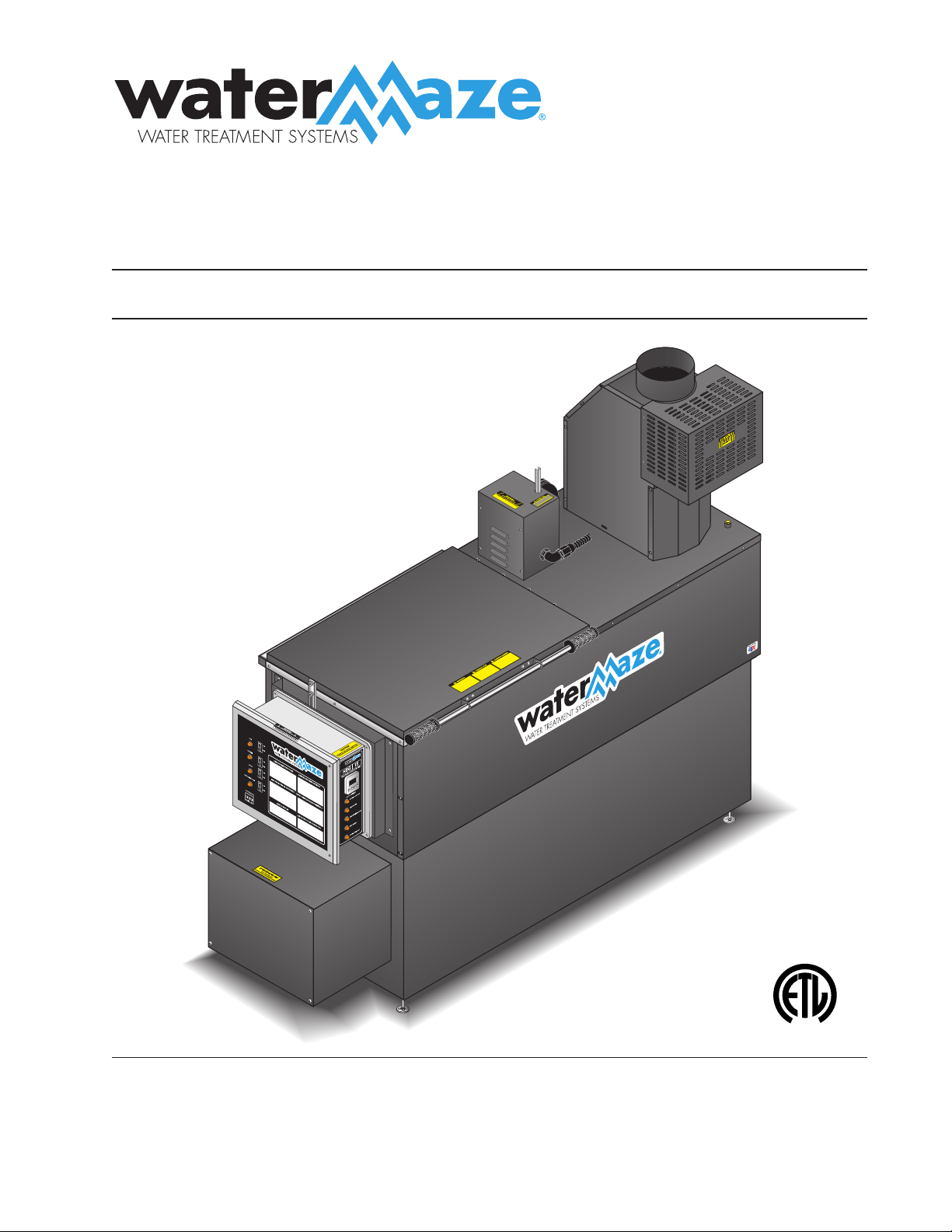
OPERATOR’S MANUAL
HBG
■ HBG-15 ■ HBG-30
For tech ni cal as sis tance or the Water Maze Dealer nearest you
visit our web page at www.wmaze.com
8.913-990.0-K10/13/20
L
I
S
T
E
D
®
89139900-1

Model Number ______________________________
Serial Number ______________________________
Date of Purchase ____________________________
The model and serial numbers will be found on a decal at tached to
the evaporator. You should record both serial number and date of
pur chase and keep in a safe place for future ref er ence.
CONTENTS
2
HBG • 8.913-990.0-K
Introduction .................................................................................................................................... 4
General Safety Information .........................................................................................................4-5
Electrical Safety Information .......................................................................................................... 5
Standard Safety Features ........................................................................................................... 6-7
Installation...................................................................................................................................... 6
HBG-15, HBG-30 Component Identifi cation .................................................................................. 7
Gas Pressure Test ......................................................................................................................8-9
Pre Start Checklist ....................................................................................................................... 10
Alarm Strobe Light Installation Instructions..................................................................................10
Operating Instructions.................................................................................................................. 11
Setting High Limit Control ............................................................................................................ 12
Maintenance ...........................................................................................................................12-13
HBG Fuel and Air Settings ........................................................................................................... 13
Auto Fill Operating Characteristics .............................................................................................. 13
Air Assisted Defoamer Operating Characteristics ....................................................................... 13
Batch Cycle Counter ...............................................................................................................14-16
Installation Dimensions ................................................................................................................ 17
Exploded View HBG-15 ..........................................................................................................18-19
Exploded View Parts List HBG-15 ..........................................................................................20-21
Exploded View HBG-30 ..........................................................................................................22-23
Exploded View Parts List HBG-30 ..........................................................................................24-25
Control Panel Exploded View ....................................................................................................... 26
Control Panel Exploded View Parts List ....................................................................................... 27
HBG Float Assembly Exploded View ........................................................................................... 28
HBG Float Assembly Parts List ................................................................................................... 29
HBG Auto Fill Option Exploded View ........................................................................................... 30
HBG Auto Fill Option Parts List ................................................................................................... 31
HBG Air Defoamer Option Exploded View ................................................................................... 32

CONTENTS
3
HBG • 8.913-990.0-K
HBG Air Defoamer Option Parts List ........................................................................................... 33
HBG Electric Auto Fill Exploded View .......................................................................................... 34
HBG Electric Auto Fill Exploded View Parts List .......................................................................... 35
HBG Electric Auto Fill Anti-Foam Kit Exploded View ................................................................... 36
HBG Electric Auto Fill Anti-Foam Kit Exploded View Parts List ................................................... 37
HBG Oil Skimmer Option Exploded View .................................................................................... 38
HBG Oil Skimmer Option Exploded View Parts List .................................................................... 39
Replacing Pump Head Tubing .....................................................................................................40
Anti-Foam Metering Pump ........................................................................................................... 41
Burner Assembly HBG-15 #P250AFEP........................................................................................42
Burner Assembly HBG-30 #HSG400 & Parts List ..................................................................43-44
Gas Train Assembly and Parts List ..............................................................................................44
Troubleshooting ......................................................................................................................45-46
HBG Cost Formulas ..................................................................................................................... 47
Specifi cations ............................................................................................................................... 47
Preventative Maintenance ........................................................................................................... 48
Warranty ...................................................................................................................................... 49
4
HBG EVAPORATOR OPERATOR’S MANUAL
HBG • 8.913-990.0-K
IMPORTANT
SAFETY INFORMATION
CAU TION: To re duce the risk of
in ju ry, read op er at ing in struc-
tions care ful ly be fore us ing.
1. Read the own er's man u al thor-
ough ly. Fail ure to fol low in struc-
tions could cause a mal func tion
of the evap o ra tor and re sult
in death, se ri ous bodi ly injury
and/or prop er ty dam age.
CAUTION: Read the in for ma tion on the serial plate
and burner la bels to verify proper fuel con nec tion.
2. All installations must com ply with lo cal codes. Con-
tact your elec tri cian, plumb er, util i ty com pa ny or the
sell ing dis trib u tor for spe cifi c de tails.
3. To pro tect the op er a tor from
elec tri cal shock, the ma chine
must be elec tri cal ly ground ed.
It is the re spon si bil i ty of the
own er to con nect this ma chine
to a UL ground ed re cep ta cle of
prop er volt age and am per age
rat ings. Do not touch machine
with wet hands or while stand-
ing in wa ter. Al ways dis con nect power be fore ser vic ing.
4. Nev er make ad just ments on the machine while it is
in op er a tion ex cept those prescribed in this man u al.
CAU TION: Use ex treme cau tion when open-
ing the lid of the evap o ra tor. Hot and pos si bly
cor ro sive steam will be emit ted.
5. DO NOT use con cen trat ed fl am ma ble liq uids that
could pose an ex plo sion haz ard.
WARNING: Flammable liquids
can cre ate fumes which can
ig nite caus ing property dam age
or se vere in ju ry.
6. WARNING: DO NOT at tempt
to evaporate flam ma ble
wastes of any kind, i.e., DO
NOT pro cess sol vents, pure
oils, etc.
7. DO NOT locate ma chine in the vi cin i ty of any fl am-
ma ble va pors, liq uids or sol ids.
8. Before servicing the machine, refer to all Safety
Data Sheet’s on the ma te ri al iden ti fi ed in the waste
stream. You must com ply with all warnings and wear
all pro tec tive cloth ing stated on the Safety Data
Sheet's.
WARNING
RISK OF
EXPLOSION. IF YOU
SMELL GAS, SHUT
OFF GAS SUPPLY.
INTRODUCTION
Thank you for purchasing a WATER MAZE HBG.
This manual covers the operation and maintenance of
HBG evap o ra tors. All information in this man u al is based
on the latest product information avail able at time of
print ing.
WATER MAZE reserves the right to make chang es at
any time without incurring any obligation.
Owner/User Re spon si bil i ty:
The owner and/or user must have an un der stand ing
of the manufacturer’s operating instructions and warn-
ings be fore us ing this WATER MAZE machine. Warning
in for ma tion should be em pha sized and understood. If
the op er a tor is not fl u ent in En glish, the manufacturer’s
in struc tions and warn ings shall be read to and dis cussed
with the op er a tor in the op er a tor’s native lan guage by
the pur chas er/owner, mak ing sure that the operator
com pre hends its con tents.
Owner and/or user must study and maintain for fu ture
ref er ence the man u fac tur ers’ instructions.
SAVE THESE INSTRUCTIONS
This manual should be considered a permanent
part of the machine and should remain with it if
machine is resold.
When ordering parts, please specify model and se-
rial number. Use only identical replacement parts.
This machine is to be used only by trained opera-
tors.
PLEASE NOTE: WATER MAZE is not responsible for
pro cure ment of regulatory and/or operating permits that
may be required by city, county, state or federal agen-
cies. It is the customer who is responsible for procure-
ment of any hazardous or non-hazardous reg u la to ry
and/or op er at ing permits, com pli ance with codes or
other gov ern men tal re quire ments associated with the
installation, use, or dis pos al of waste associated with this
equip ment. Sub merged combustion can be clas si fi ed as
incineration in specifi c jurisdictions. It is the customer's
re spon si bil i ty for pro cure ment of appropriate local and
state per mits as needed.
The guidelines listed in the evaporator feasibility report
are specifi c only to the waste stream submitted for the
eval u a tion and estimated emissions. Moreover, WATER
MAZE is not responsible for the operation or main te-
nance of the evaporator unit. If the unit is subjected to
any waste stream other than that which has been tested
by the named lab o ra to ry, op er a tion may cause adverse
effects on the equip ment and will negate any warranty
of parts or equipment.
READ OP ER A TOR’S
MAN U AL THOR OUGH LY
PRIOR TO USE.
CAU TION
TO AVOID ELEC TRIC
SHOCK, GROUND
MACHINE PROPERLY.
DANGER
HBG EVAPORATOR OPERATOR’S MANUAL
5
HBG • 8.913-990.0-K
9. When the machine is work ing, do not cover or place
in a closed space where ventilation is in suf fi cient.
Avoid in stall ing ma chines in small con fi ned ar eas.
Ad e quate ox y gen is need ed for the evap o ra tion pro-
cess. Standard minimum clearances for this type of
appliance is 18" from fl oor, sides and rear and 48"
from electrical control box. The minimum clearance
from the vent stack is 18". This appliance must be
installed on non-combustible fl oors.
10. The HBG and components will freeze if not in
op er a tion. In cold cli mates locate HBG in heated
en clo sure.
11. Run ning the system with out water damages the tank
fl oor and voids the war ran ty.
NOTE: Allow tank to cool before adding wastewater
or dam age will occur to tank fl oor due to ther mal
shock.
12. The HBG must be installed and train ing provided by
an au tho rized deal er.
13 Do not operate the equip ment in an unvented, en-
closed area. Car bon mon ox ide may ac cu mu late.
14. If you smell gas, shut off the gas
sup ply valve, ex tin guish any
open fl ame and test all joints
with a soap so lu tion. If the odor
per sists, call your gas sup pli er
im me di ate ly.
15. Only those liquid wastes
that have been approved by
WATER MAZE, and the prop er
regulatory agencies, should be
placed in the HBG ma chine. Test
methods as outlined in WA TER MAZE Pro fi le 3518
must be ob tained. NOTE: WA TER MAZE
is not li a ble
for the per for mance and the warranty will be void
when waste liq uids that are not test ed and ap proved
are in tro duced into the HBG.
16. Chemistry limitations include:
Maximum 1,000 mg/L chlo rides for 316L stain less
steel.
Maximum 40,000 mg/L chlo rides for AL-6XN
stainless steel pH be tween 7.0 and 9.0.
Initial oil concentration be tween 500 and 5,000
mg/L or a corrosion in hib i tor for car bon steel.
Deviations from these parameters must be ap proved
by Engineering.
ELECTRICAL SAFETY
Ground equipment before con nect ing to the elec tri cal
pow er sup ply.
Fail ure to ground the equip ment can
cause a se vere or fa tal elec tri cal
shock haz ard.
Do not ground to a gas sup ply line.
To avoid dangerous or fatal elec tri cal
shock, dis con nect the pow er to the
equip ment be fore work ing on any elec-
tri cal con nec tion or making any re pairs.
Supply voltage must be within ± 10%
of the name plate volt age. In cor rect volt age can cause
a fi re or seriously dam age the equip ment and void the
war ran ty. If in doubt, con sult a li censed elec tri cian.
Con nect the equipment to a ded i cat ed circuit break er.
DANGER: This machine is
equipped with an elec tron ic ig-
ni tion sys tem. Light ing of the
pi lot is ac com plished through
elec tron ic spark ignition. Do not
at tempt to light the ap pli ance
man u al ly as a burn in ju ry or elec-
tri cal shock may result.
WARNING
RISK OF EX PLO SION:
DO NOT USE WITH
FLAMMABLE
LIQUIDS.
FOR YOUR SAFETY READ BEFORE LIGHTING
WARNING
If you do not follow these instructions exactly, a fi re or explosion
may result, causing property damage, personal injury or loss of
life.
A. This appliance has a pilot which must be electrically ignited.
When lighting the pilot, follow these instructions exactly.
B. Before lighting, smell all around the appliance area for gas. Be
sure to smell next to the fl oor because some gas is heavier than
air and will settle on the fl oor.
FOR YOUR SAFETY
WHAT TO DO IF YOU SMELL GAS
Do not try to light any appliance.
Do not touch any electrical switch. Do not use any phone in the
building.
Immediately call your gas supplier from a neighbor’s phone. Follow
the gas supplier’s instructions.
If you cannot reach your gas supplier, call the fi re department.
C. Use only your hand to push in or turn the gas control knob.
Never use tools. If the knob will not push in or turn by hand, don’t
try to repair it.
Call a qualifi ed service technician. Attempted repair or use of
force may result in a fi re or explosion.
D. Do not use this appliance if any part has been under water.
Immediately call a qualifi ed service technician to inspect the
appliance and to replace any part of the control system and
any gas control which has been under water.
HAZ ARD OUS VOLTAGE
CAN SHOCK, BURN
OR CAUSE DEATH.
GROUND SYS TEM
BE FORE CON NECT ING
TO POW ER SUPPLY.
DANGER
HAS ELEC TRON IC
SPARK IG NI TION.
DO NOT AT TEMPT
TO LIGHT MAN U AL LY.
DANGER

6
HBG EVAPORATOR OPERATOR’S MANUAL
HBG • 8.913-990.0-K
STANDARD
SAFETY FEATURES
The HBG uses gas and electricity to op er ate. This can
be a fatal com bi na tion if not handled prop er ly. For this
rea son, the HBG has been designed with safe ty in mind.
You will fi nd these standard safe ty features on all HBG
equip ment:
1. Batch Cycle Controller
This controller counts how many times the ma chine
has evap o rat ed and re fi lled. At a pre de ter mined
num ber of batch cycles, the controller will shut down
the evap o ra tor. Main te nance must be per formed
be fore the batch cy cle controller is re set.
2. Low Water Float Switch
This fl oat switch insures that there is water cov er-
ing the fl oor of the evaporator. When the water lev el
drops to a certain level, the low water fl oat switch
turns off the burner.
3. High Water Float Switch
This fl oat will turn off the HBG when the water lev el
be comes too high.
4. On-Off Switch
The burner on-off switch dis con nects power to the
burn er.
5. High Tem per a ture Switch with Manual Reset
If the underneath fl oor temperature below the tank
exceeds 500° for the HBG-15 & HBG-30, the manual
reset temperature switch will trip, turning off the
burner. To reset, push the black button on the side
of the electrical box.
6. High Temperature Alarm
Included with your HBG is a combination strobe
light and horn alarm that will warn of a high tem-
perature condition within the HBG tank. This alarm
is automatically actuated on high temperature by
two thermal switches mounted on the outside wall
of the tank. These thermal switches are factory set
at 300° F and are designed to set off the strobe/horn
alarm as well to shut down the machine. This alarm
unit must be fi eld mounted (see page 26) and wired
(see wiring diagram) to the HBG control panel. The
strobe light has a fl ash rate of 75 fl ashes/minute. The
audio alarm has a sound level of 81 dBA @ 10ft.
INSTALLATION
1. LOCATION-Locate the HBG evaporator on a con-
crete surface and level with leveling feet supplied
with the machine.
NOTE: Leveling feet must be screwed into the bot-
tom of the fl ame box when it is removed from pal-
let. HBG-30's must have fi fth leveling foot screwed
into the burn er support bracket located below the
burner. Burn er sup port bracket is to keep the burn er
level at all times. Pro tect machine from damaging
en vi ron ments such as wind, rain, sun and freezing
tem per a tures.
CAUTION: For natural gas, air ven ti la tion should
be lo cat ed near the ceiling. For liquid pro pane,
air ven ti la tion should be located near the fl oor.
Air ven ti la tion open ings and evaporator stack
should be lo cat ed a safe dis tance from build ing
cli mate con trol air in take ducts.
2. ELECTRICAL-The standard HBG requires 120
volts. Re fer to the se ri al plate for proper volt age and
amp re quire ments for your machine. All elec tri cal
lines must be tested with a volt age meter for proper
volt age and polarity be fore con nect ing to the HBG.
CAUTION: All electrical lines must be installed
by qualifi ed personnel only. All installations must
be elec tri cal ly grounded and conform to all local
and Na tion al Electrical codes.
NOTE: The serial plate lists multiple AMP ratings.
Use the one that matches your purchased unit and
options. The fi rst Amp rating on the serial plate is
the standard unit with no air or electrical-powered
options. The AIR Option Amp rating is for the unit with
any air-powered auto-fi ll and/or chemical defoamer
injection options. The ELEC Option Amp Rating is for
the unit with any electric motor or solenoid-powered
auto-fi ll and/or chemical de-foamer injection options.
Refer to the Amp rating that applies to your unit when
installing.
Use a strain relief at the rear of the control panel
for con nect ing to the main power supply. Elec tri cal
con duit must be run all the way to the con nec tion
point in ac cor dance with local codes. To con nect
the pow er wires inside the elec tri cal box, lo cate the
wir ing ter mi nal strip and follow wiring di a gram to
make sure black wire is connected to the prop er
ter mi nal. Con nect the white neu tral wire to ter mi nal
#N. Then con nect the ground wire to the ground ing
stud on the back of the elec tri cal box. Con fi rm that
volt age is go ing to the cor rect ter mi nals.
3. AUTO FILL FLOAT - Remove fl oat wires from pump
switch (black and white wires). With strain relief sup-
plied, attach to waste wa ter tank near bottom and
thread fl oat wires through strain relief and tight en.
Note: Leave at least a 3 inch tether from the strain
relief for fl oat to work correctly. Re wire fl oat wires
into pump switch.
4. GAS PIPING - All piping must comply with local
codes and ordinances or the National Fuel Gas Code
ANSI Z223. 1-1984 and NFPA No. 54. A sed i ment
trap or drip leg must be installed in the sup ply line
to the burn er.

HBG EVAPORATOR OPERATOR’S MANUAL
7
HBG • 8.913-990.0-K
89139900-2
Control
Panel
30-817
Float Assy.
Auto-Fill Inlet
Auto-Fill Inlet
Exhaust Fan
30-817
Float Assy.
Burner Assy.
COMPONENT IDENTIFICATION
HBG-15 TOP
HBG-30 BOTTOM
Alarm/Strobe
(Must be installed for
proper machine operation)
Control
Panel
Burner Assy.
Exhaust Fan
Alarm/Strobe
(Must be installed for
proper machine operation)
8
HBG EVAPORATOR OPERATOR’S MANUAL
HBG • 8.913-990.0-K
A union shall be installed in the gas line adjacent
to and upstream from the control manifold and
downstream from the manual main shut off valve.
A 1/8" N.P.T. plugged tap accessible for test gauge
con nec tion shall be installed immediately up stream
of the gas supply connection for the purpose of
de ter min ing the gas supply pressure to the burn er.
A manual shut off valve shall be installed in the gas
sup ply line external to the appliance.
The gas line should be a separate supply direct from
the meter to the burner. It is recommended that new
pipe be used and located so that a min i mum amount
of work is required in future ser vic ing. Piping should
be durable, substantial and gas tight. It should be
clear and free from cutting burrs and defects in
struc ture or threading. Cast iron fi t tings or aluminum
tub ing should not be used for the main gas supply.
Joint com pounds (pipe dope) should be used spar-
ing ly on male threads only and be ap proved for all
gases.
The building structure should not be weakened by
in stal la tion of the gas piping. The piping should not
be sup port ed by other piping, but should be fi rmly
sup port ed with pipe hooks, straps, bands or hang ers.
Butt or tap welded pipe should not be bent.
The gas piping should be so installed as to pre vent
an accumulation of condensation and it must be
pro tect ed against freezing. A horizontal pipe should
be pitched so that it grades toward the meter and is
free from sags. The pipe should not be run through
or in an air duct or clothes chute.
The HBG and its individual gas valve must be dis-
con nect ed from the gas supply piping system dur ing
any pressure testing of the system at test pres sures
in ex cess of 1/2 psig.
TESTING PIPING FOR LEAKS - Before allowing
gas un der pressure into the piping, all openings
from which gas can escape should be closed. Im-
me di ate ly after turn ing on gas, the system should
be checked for leaks. This can be done by watch-
ing the 1/2 cubic foot test dial for 5 minutes for any
move ment, or by soap ing each pipe con nec tion and
watch ing for bubbles. If a leak is found, make the
nec es sary re pairs and re peat the above test.
Defective pipes or fi ttings should be replaced and
not re paired. Never use a fl ame or fi re in any form
to lo cate gas leaks—use a soap solution.
After the piping and meter have been checked com-
plete ly, purge the system of air. Be sure to relight all
the gas pilots on other appliances.
PURGING
- After the piping has been checked, all
pip ing and appliances receiving gas through the
meter shall be fully purged. A suggested meth od for
purg ing the gas line to the burner is to dis con nect
the pilot line at the outlet of the pilot valve. Under
no cir cum stanc es shall the line be purged into the
com bus tion chamber.
After the gas line to the burner has been fully purged
and the pilot line reconnected, the gas supply at
oth er pilot burners, lo cat ed on other gas ap pli anc es
which were ex tin guished as the result of in ter rupt ed
ser vice, shall be re ig nit ed.
GAS SUPPLY PIPE & PRESSURE - The burner gas
valve will accept a 3/4" (HBG-30) and 1/2" (HBG-15)
gas line.
The min i mum in let gas sup ply pres sure is 6" W.C. for
nat u ral gas and 11.0" W.C. for L.P. gas; the max i mum
gas sup ply pressure is 14" W.C. for natural gas and
L.P. gas (va por). A regulator may be need ed to obtain
the re quired pres sure. Refer to chart on page 12 for
set tings.
5. WASTEWATER - Wastewater is in tro duced into the
evap o ra tor us ing a buck et or the op tion al autofi ll
pump. A 20 mesh stain less steel strain er pro tects
the pump from de bris. The con nec tion be tween the
above ground waste wa ter tank and the HBG ma chine
is made by us ing a 3/4" I.D. or larg er sup ply hose
with common con nec tors supplied by the cus tom er.
The con nec tion is lo cat ed on the rear of the machine
where the 20 mesh strain er is con nect ed to the pump.
WATER MAZE rec om mends the in stal la tion of a ball
valve next to the strain er that will allow stoppage of
the waste stream dur ing main te nance. A 3" sludge
valve 8.707-229.0 is rec om mend ed (not sup plied)
to al low easy re mov al of sludge and con cen trat ed
waste wa ter.
GAS PRESSURE TEST
HBG- 15 Burner
High
Low
High
Low
Inlet Gas
Pressure
Manifold
Pressure

HBG EVAPORATOR OPERATOR’S MANUAL
9
HBG • 8.913-990.0-K
NOTE: The HBG op tion al autofi ll air diaphragm
pump is au to mat i cal ly con trolled by fl oats and will
sup ply waste wa ter as need ed after startup.
CAUTION: Foam ing chemicals will af fect the
evap o ra tion pro cess in the HBG. An anti-
foaming agent may need to be added to coun-
ter act the foam.
An automatic anti-foam dispenser can be used to
au to mat i cal ly add anti-foam (8.906-074.0). Contact
your WATER MAZE representative to pur chase the
de foam er best suit ed to your ap pli ca tion. (De foam er
sold sep a rate ly.)
6. VENTING - Each evaporator must have its own vent
stack — A 6" vent pipe (HBG-15) and 10" vent pipe
(HBG-30). The stack temperature will reach 650°F.
Recommended Materials:
1.Type L Vent Pipe
2. Stainless Steel Pipe
3. Boiler Stacking
NOTE: If possible, the stack should be a single piece.
However, if the stack has seams, the seams must be
sealed with duct sealant to prevent mois ture leaks;
since the exhaust is water saturated. A tube of RTV
silicone will be supplied with each ma chine shipped
for this pur pose. Moisture leakage may result in
dam age to the HBG electrical sys tems. All stack
in stal la tions must be per formed only by qualifi ed
per son nel.
The top of the exhaust stack should be suffi ciently
high above the roof for proper dispersion of the
ex haust. The stack should be unobstructed and in
com pli ance with all local and federal codes. Avoid
90° bends in the stack. A straight stack is always
best.
A vertical dis charge design should be used, to geth er
with a vertical rain diverter. A con ven tion al rain cap is
not rec om mend ed for the HBG because of in duced
back pres sure. A vertical rain diverter is an over-
sized piece of stack ma te ri al that is con cen tric with
the stack. The diverter ex tends 6" down over the top
of the stack to al low fl ex i bil i ty in po si tion ing fas ten ers.
Both rain pro tec tion and back pres sure re duc tion is
achieved with this de sign. This type of rain diverter
can be pur chased from your local deal er.
7. Air Requirements - An air compressor capable
of de liv er ing a minimum of 4 cubic feet per minute
(CFM) of air at 60-100 psi to work the op tion al auto
fi ll air di a phragm pump and air as sist ed defoamer
sys tem. NOTE: Air supply must be on at all times
for ma chine to op er ate
2' Min.
6" Flue Rain Cap
(optional) 8.717-740.0
10" Flue Rain Cap
(optional) 8.717-742.0
Roof
10
HBG EVAPORATOR OPERATOR’S MANUAL
HBG • 8.913-990.0-K
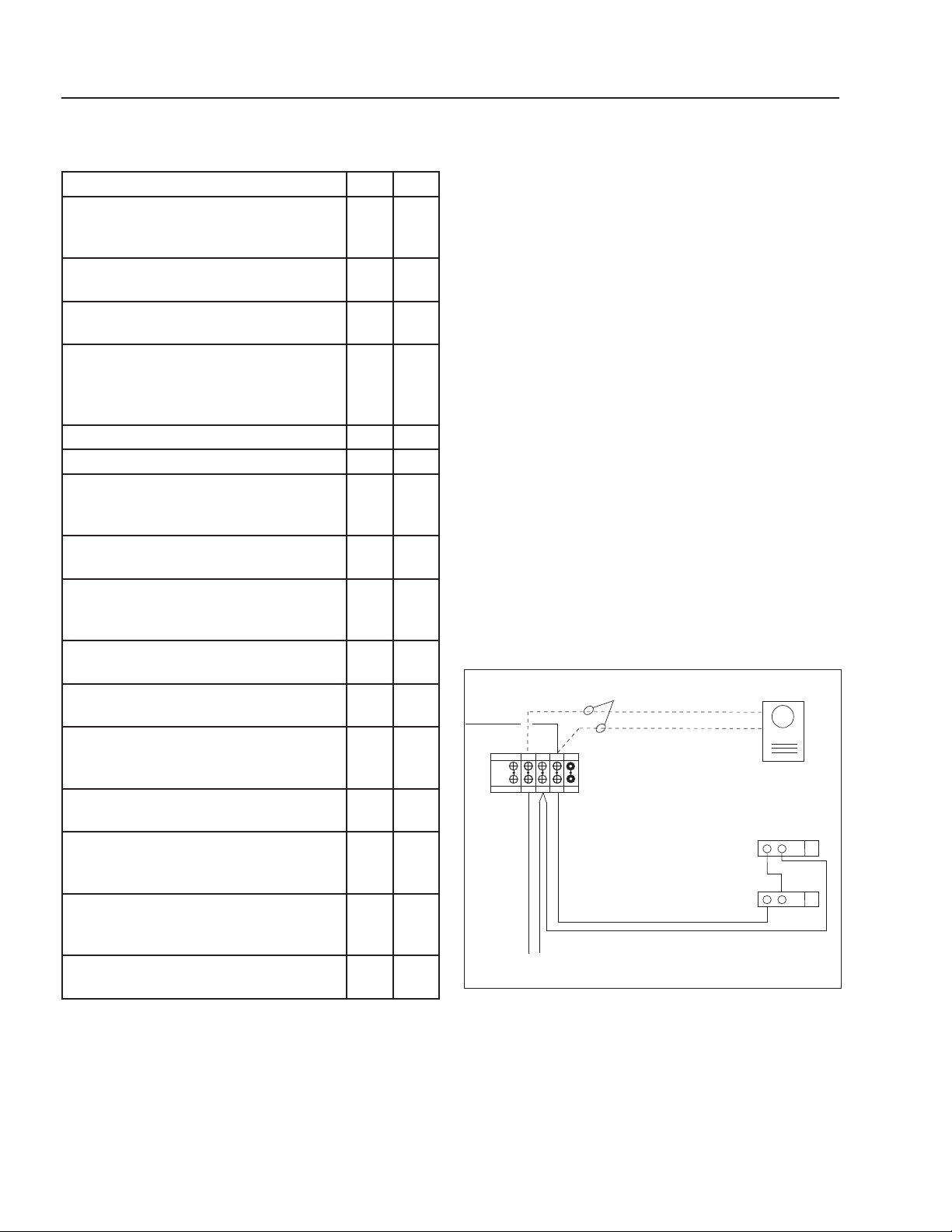
ALARM STROBE INSTALLATION - Locate
a position in which to install the strobe light
assembly that will be visible to alert someone
of this alarm.
CAUTION: Disconnect Power Before
Servicing. From the terminal strip inside the
machine's electrical box, connect a black and
white 18 gauge wire (fi gure 1), then run them
through conduit to the Alarm Strobe Light with
Horn Assembly. These wires will be 120 volt!
Inside the strobe light assembly you will fi nd
4 screw terminals. Install the 2 jumper wires
included and wire per instructions provided with
the strobe light assembly.
Connect the black wire to terminal #4 and the
white wire to terminal #2 in the HBG electrical
box per fi gure 1.
ATTENTION! The alarm/strobe supplied with this
machine is specially designed to draw attention
to abnormal conditions and alert employees.
This device must be installed on the wall near
the machine in clear view of the operator. See
pages 6, 10 & 26 for instructions.
INSTALLING THE ALARM
STROBE LIGHT ON THE HBG
Figure 1
WB
120V
Field Wiring
PRE-START CHECK LIST
YES NO
Has gas supply been inspected by an
authorized contractor to meet local
codes?
Has air supply hose been connected
and adjusted?
Is machine shielded from moisture or
water spray?
Is the voltage correct and are the circuit
breaker and supply cord adequate
according to specifi cations and serial
plate notation?
Is the machine electrically grounded?
Is there ample wastewater supply?
Have all fl ammable liquids or gases
been removed from the installation
location?
Is there adequate gas supply for the
BTU rating of the burner?
Is incoming gas supply pressure to
the machine between 6-14 w.c.i. or 1/2
psig?
Has the proper gas regulator been
installed for pressure and volume?
Is the machine properly vented to allow
adequate fl ow?
Are the propane tanks large enough,
according to the rating of the machine,
to prevent freezing?
Have gas lines been checked for gas
leaks?
Have all operators using this machine
been instructed properly and have they
read the manual?
Has the machine been installed
according to the operator’s manual
instructions?
Has wastewater pH been adjusted
between 8 - 10?
CAUTION: If “NO” has been checked on any of the
above questions, do not operate the machine.

HBG EVAPORATOR OPERATOR’S MANUAL
11
HBG • 8.913-990.0-K
OPERATING INSTRUCTIONS
NOTE: If the waste stream being evaporated does
not con tain between 500-5000 mg/L of oil and you
are us ing a mild steel tank, it is ex treme ly im por tant
to add 1 quart of 20 to 40 weight chemical oil to the
HBG-15 tank (2 quarts to the HBG-30 tank) each time
main te nance is per formed. This amount of oil will
equal approx. 1/8" of oil on the top surface of the
HBG liq uid. This ad di tive will im pede corrosion. If
this op er a tion is not per formed, the tank warranty
will be void.
1. Supply the HBG-15/30 with 120 volts on a 15 amp
ser vice. NOTE: All supply voltage wires must be
wired into the elec tri cal box and connected to their
re spec tive ter mi nal bar strip positions or ground-
ing lugs. Refer to wir ing diagram supplied with the
machine. Important to check wire polarity.
2. Fill the evap o ra tor tank with waste wa ter to the bot-
tom of the top safe ty fl oat. WARNING: If the HBG
liq uid level is too high, the high level safety fl oat will
not al low the machine to op er ate.
3. Turn the fan switch to the ON position.
NOTE: The fan switch must be on for any other
com po nents to operate.
4. If equipped with the optional auto fi ll air diaphragm
pump, con fi rm the wastewater inlet line is con nect ed
to the inlet fi lter garden hose swivel connector.
5. Confi rm that the external normally open fl oat with the
auto fi ll option in the wastewater holding tank is in the
up po si tion. If the fl oat is in the down position when
the pump switch is in the auto position, the pump
will not op er ate. If the pump switch is in the manual
po si tion the external fl oat will be by passed.
6. Push the pump switch to the “auto” position (auto fi ll
option). The pump will turn on, fi lling the tank with
wastewater. The top fl oat inside the tank turns the
pump “off.”
7. Turn gas control valve knob to “ON”.
8. Push the burner switch to the “ON” position. If the
low water fl oat is in the up position the burner be gins
the ignition process.
NOTE: The low water fl oat is con trolled by a timer
to alleviate the burn er from being turned on and off
due to boiling water agitation. When the low water
fl oat is moved from the down to the up position, the
tim er will initiate timing for 10 seconds before the
burn er is initiated.
The ignition process is as follows:
A. Trial for pilot ignition: The fl ame module checks
that a safe start fl ame simulating con di tion ex-
ists. A fan prov ing switch proves the burner fan is
op er at ing. If it is not operating, the burn er will not
ig nite.
B. Pilot ignition: The fl ame mod ule opens the gas
pilot valve. Si mul ta neous ly, the electronic spark
gen er a tor ignites the pilot. Once the pilot has
ig ni tion, the electronic spark gen er a tor turns off.
The pilot ignitor/sensor rod proves there is fl ame at
the pilot. If there is no fl ame at the pilot the burn er
goes into a safety lockout period.
C. Main fl ame ignition: Once the burner pilot sen-
sor is proven the main gas solenoid valve opens
al low ing full burner operation. If the fl ame goes
out, the pilot electronic spark gen er a tor attempts
to re ig nite the pilot.
NOTE: If the burner does not ignite, confi rm the
gas so le noid valve on/off switch is in the “ON” po-
si tion and that the manual reset high tem per a ture
switch has not tripped due to low water or high
sol ids build up inside the HBG tank. The re set
but ton is on the back of the control box.
9. Remove the plug at the gas solenoid valve manifold
and in stall a hosebarb fi tting. Attach a 0-10" W.C.
ma nom e ter. With the burner operating, adjust the
reg u la tor valve to the proper setting ac cord ing to
the chart below.
10. When the predetermined batch cycle count has been
reached and after maintenance has been per formed,
restart the machine by push ing the re set button on
the batch cycle counter la beled F1/RST.
11. To operate the optional oil skimmer, turn the burner
to the “OFF” position al low ing oil to fl oat to the top
of the tank. Lift the tank lid and attach the oil skim-
mer to the outer wall of the tank. Allow the stain less
belt to pick up all the fl oating oil in the wastewater
tank. Place a buck et under the down spout of the oil
skim mer to col lect the oil.
The evaporator will operate con tin u ous ly until 1) the
batch con trol ler hits its predetermined num ber of
batch cycles. 2) the wa ter gets too low in the waste-
wa ter hold ing tank (auto fi ll op tion). 3) the water lev el
in the waste wa ter tank causes the bottom fl oat to trip
off the burn er. Once the liquid lev el fl oat has ris en,
the burn er will au to mat i cal ly re start.

12
HBG EVAPORATOR OPERATOR’S MANUAL
HBG • 8.913-990.0-K
SETTING LIMIT CONTROL
Adjust the high limit control temperature accordiningly.
MAINTENANCE
CAUTION: Use protective gloves, goggles and any
oth er protective clothing re quired by law for chem i-
cals mixed with the waste stream.
The HBG does not require a lot of main te nance, but it
does require con sis tent main te nance. The fre quen cy of
main te nance var ies de pend ing on what is in the water
that is be ing evap o rat ed.
Gen er al maintenance consists of re mov al of sludge from
the bottom and removal of any fl oat ing oil at the top of
the evap o ra tion tank.
WARNING - Shut down the HBG and allow it to cool
be fore performing any main te nance. Do not al low
pump to run long er than 5 min utes with out wa ter.
Dis con nect all hos es to allow wa ter to drain.
OIL REMOVAL - If you have excess fl oating oil in the
evaporation tank liq uid that needs to be re moved, shut
down the HBG and let the oil fl oat to the top. Attach oil
skimmer to side of tank and plug into own power source.
Turn on the oil skim mer and col lect oil in a buck et.
SLUDGE REMOVAL - Remove the low er 3" sludge
drain cap on the side of the evaporator allowing sludge
and wa ter to es cape. Use a small shovel to remove the
re sid u al sludge from the bottom of the tank. Removing
the sludge and clean ing the fl oor of the evap o ra tor will
great ly im prove the evap o ra tion rate.
NOTE: Allowing sludge to ac cu mu late on the fl oor of the
HBG can cause warpage, corrosion and or heat stress to
the fl oor. A build-up of solids will cause the manual reset
high tem per a ture switch to trip not al low ing the burn er
or pump to op er ate. Remove the sludge, refi ll the tank
and restart the machine.
WARNING: Allowing sludge to build up on the in side
fl oor of the HBG can cause warpage to the fl oor of
the tank and will void the warranty.
DRAFT INDUCER: On a monthly main te nance sched-
ule, clean ing of the fan blade fi ns and ex haust stack ing
must be done to re move any sludge build-up that can
re duce the evap o ra tion ef fi cien cy. To clean the fan blade
fi ns, start with the water cool and the fan switch on the
control panel in the off po si tion. Next, remove the six tek
screws that at tach the fan to the stack. Pull the in duc er
fan away from stack and scrape debris from blade fi ns.
On reassembly, place a small bead of high heat sil i cone
around the outer edge of the in duc er housing on each
tek screw to seal out any pos si ble air leaks.
WEEKLY MAINTENANCE
1. Turn all power switches to the “OFF” position.
2. Allow the wastewater to cool.
3. Position a sludge container under the sludge valve.
Open the sludge valve and remove the remaining
waste liq uid.
4. After every batch is complete, scrape the fl oor and
in te ri or walls of the HBG tank, transferring the sludge
into the sludge con tain er.
5. Remove any buildup that has accumulated on the
ex te ri or of the tank and exhaust pipe.
6. Clean the liquid level fl oats, remove any ac cu mu la-
tion that may coat the fl oats and not allow them to
move freely.
7. Clean all three wastewater fi lter screens if auto fi ll
option is installed. (i.e. both inlet strainers and one
underneath the Parker solenoid brass cap)
8. If the evaporator is not in use at least twice per week,
then clean out and rinse with fresh water, and let sit
empty.
9. Check tank and lid for corrosion after each com plete
batch.
500° for HBG-15 & HGB-30

HBG EVAPORATOR OPERATOR’S MANUAL
13
HBG • 8.913-990.0-K
HBG FUEL AND AIR SETTINGS
Natural Gas GPH Gas Orifi ce Inlet Gas Supply Pressure Man. Pressure Air Setting
HBG-15D 10 - 15 G (.261) 4.5 - 14 WCI 3 WCI Open Draft Wheel 6 Full Turns
HBG-30D 25 - 30 T (.468) 5.5 - 14 WCI 3 WCI Draft Open to 4
Liquid Propane GPH Gas Orifi ce Inlet Gas Supply Pressure Man. Pressure Air Setting
HBG-15D 10 - 15 #22 (.157) 11 - 14 WCI 5 WCI Open Draft Wheel 6 Full Turns
HBG-30D 25 - 30 Q - (.332) 5.5 - 14 WCI 5 WCI Draft Open to 8
SEMI ANNUAL MAINTENANCE
1. Check auto fi ll pump for proper pressure, fl ows and
electrical capacities.
2. Check auto fi ll fl oats for proper operation.
3. Oil the draft inducer motor bearings. Oil holes are
pro vid ed at front and rear faces of motor. CAUTION:
Not more than 3 drops of S.A.E. 20 oil should be
used.
4. Check tank and lids for corrosion.
5. Check burner for proper operation and gas
pres sure.
AUTO FILL OPERATING
CHARACTERISTICS
The auto fi ll option consists of two level control switches
which control the fi ll pump. The lower level switch turns
the pump on. As the wa ter level raises, the upper level
switch turns the pump off. The evaporator then evap o-
rates the water, which in turn lowers the water lev el past
the low er level switch, which turns the pump on and
starts the fi ll pro cess.
NOTE: To engage the auto fi ll feature, push the pump
switch to auto. This will allow the pump to be con trolled
by the auto fi ll fl oat level switches. Push ing the pump
switch to man u al will bypass the external N/O teth ered
fl oat in the waste wa ter holding tank.
AIR ASSISTED
DEFOAMER OPERATING
CHARACTERISTICS
The air assisted defoamer option consists of a metering
pump drawing up defoamer and a solenoid controlling the
air injecting the defoamer through a fan nozzle lo cat ed
in side the wastewater tank. Set the three position switch
to “auto” and de foam er will then be injected every time
the machine refi lls. If more defoamer is needed, turn
ad just ment screw, located under cover plate in front
of pump, clockwise to increase pump speed. Injecting
man u al ly is also avail able. NOTE: The air pres sure
need ed to op er ate the de foam er must not ex ceed 2 psi.
14
HBG EVAPORATOR OPERATOR’S MANUAL
HBG • 8.913-990.0-K
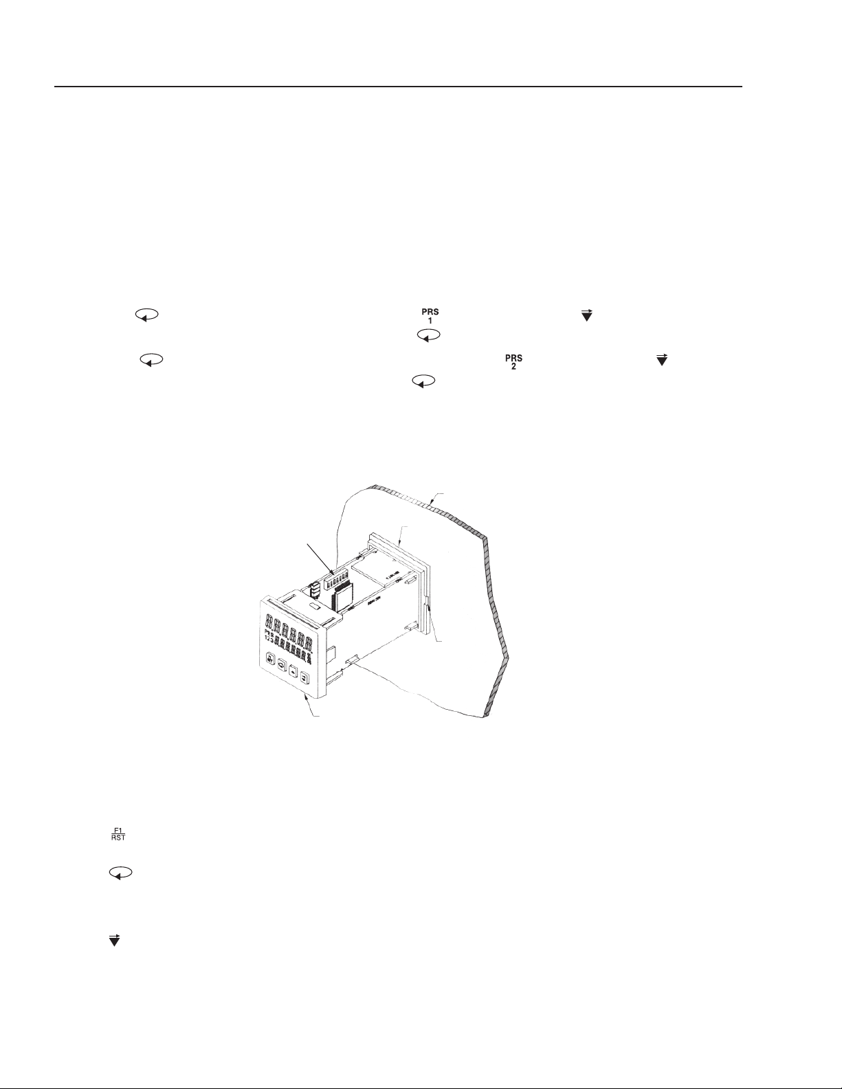
Batch Cycle Counter Quick
Reprogramming Instructions
Function Settings
Reset Button. Push to restart machine after batch cycle com plet ed.
Scroll Button. Push to select the different programming modes. Also
saves program values.
Vertical Scroll changes programming values.
Horizontal Scroll for multiple values. Also changes pro gram ming values.
▲
1. Pull face plate of batch cycle counter out of its holder in electrical box with your fi ngers . Dip switch #7,
located along left side (wall) of circuit board, needs to be switched to the down (OFF) position. This will
allow for reprogramming. Slide batch counter back into its holder.
2. Press button until LED screen in green shows ( #
02
). Push the ▲ or button until the new
batch cycle count appears in green. Then press the button once to save the setting for preset 1.
3. Press button once more. The LED screen in green will show ( #
02
). Push the ▲ or until the
value in green is the same value in preset 1. Press button to save setting for preset 2.
4. Remove batch cycle counter once again from its holder in the elec tri cal box. Change the setting on dip
switch #7 to the up (ON) po si tion. Slide the batch counter back into its holder in the elec tri cal box.
NOTE: # stands for batch count val ue
Elec tri cal Box
Holder
Pry Slot
Face Plate
Dip
Switch es

HBG EVAPORATOR OPERATOR’S MANUAL
15
HBG • 8.913-990.0-K
13. Press button, (P1tr Ac) will appear in red. Value
(no) will appear in green. No change is necessary.
14. Press button, (Ac Out) will appear in red.
(-L-L-L) will appear in green. No change is necessary.
15. Press button, (OutrES) will appear in red.
(0.01SEC) will appear in green. No change is nec-
es sary.
16. Press button, (OutPut) will appear in red.
(1t 0.10) will appear in green. No change is nec es sary.
17. Press button, (OutPut) will appear in red.
(2t 0.10) will appear in green. No change is nec es sary.
18. Press button, (OutPut) will appear in red.
(3t 0.10) will appear in green. No change is nec es sary.
19. Press button, (rEUOut) will appear in red.
(-n-n-n) will appear in green. Press button until mid dle
(-n) value is blinking. Press ▲ button until (-y) value is
show ing.
20. Press button, (rEUAnu) will appear in red.
(-n-n-n) will appear in green. No change is nec es sary.
21. Press button, (OutP.uP) will appear in red.
(PPP) will appear in green. Press button until left
(P) value is blinking. Press ▲ button until (P) val ue
ap pears. Do the same for center and right, all values
should read (-P)
22. Press button, (USr In 1) will appear in red.
(rSt. -L) will appear in green. Press ▲ button until
(Pro.dis) ap pears.
23. Press button, (USr FI) will appear in red. (rst-
L) will appear in green. No change is necessary.
24. Press button, (CodE) will appear in red. Value
(0) will appear in green. No change is nec es sary.
25. Press button, (ScroLL) will appear in red.
(no)
will appear in green. No change is necessary.
26. Press button, (FAcSEt) will appear in red. (no)
will appear in green. No change is necessary.
27. Press and hold button for 2 seconds. (Prog)
will appear in red and (SAVE) will appear in green.
To complete setting the batch counter, fi rst pull the face
plate of the batch counter out of its holder with your fi n-
gers. This will expose the internal circuit boards. Along
the left side (wall) circuit board are the dip switch es.
These switch es are numbered 1 through 7. Switches 2,
5, and 7 need to be in the up (ON) po si tion.
Slide the batch counter back into its holder. Initial pro-
gram ming of the batch cycle con trol ler is now complete.
(NOTE: Programming cannot be performed if dip switch
#7 in the up (ON) position). If ad just ment to the batch
cy cle count value is to be re pro grammed, dip switch #7
needs to be in the down (OFF) position. When re pro -
gram ming is com plete, set dip switch #7 back to the up
(ON) position).
INITIAL PROGRAMMING OF
BATCH CYCLE COUNTER
Function Settings
Reset Button. Push to restart machine after batch
cycle completed.
Scroll Button. Push to select the different pro-
gram ming modes. Also saves program values.
Vertical Scroll changes programming values.
Horizontal Scroll for multiple values. Also chang es
pro gram ming values.
NOTE: Original batch counter has been preset at
factory.
Programming
1. Press and hold button for 2 seconds. (Entry) will
ap pear in red. (Auto Sc) will appear in green. No change
is necessary.
2. Press button once, (Ac PSc) will appear in red.
(-L) will appear in green and does not need to be
changed.
3. Press button, (PSc ALr) will appear in red.
(1.00000) will appear in green and does not need to
be changed.
4. Press button, (dEc Pt) will appear in red.
(------) will appear in green. This value can't be changed.
5. Press button, (Cnt In) will appear in red. (Cl-ud)
will appear in green. No change is nec es sary.
6. Press button, (OPEr 1) will appear in red. (11) will
appear in green. Press button until (1) is show ing.
7. Press button, (C2 ASn) will appear in red. (bAtch)
will appear in green. No change is nec es sary.
8. Press button, (OPEr 2) will appear in red. (1) will
ap pear in green. No change is necessary.
9.Press button, (Ac PrS) will appear in red.
(-y-y-y) will appear in green. Press button until the far
left (-y) value is blinking. To change, press ▲ button until
(-L) is showing. Press once, the middle (-y) value
will blink. Press ▲ button until (-n) is showing. Press
button once more and the far right (-y) will blink. Press
s but ton until (-n) is showing.
10. Press button, (PrESEt) will appear in red. The
value to set is predetermined from the waste wa ter anal-
y sis. This value is known as PRS1 (Preset 1). Press the
▲ or buttons to set the batch cycle value.
11. Press button, (PrESEt) will appear in red. This
value, PRS2 (preset 2), must be set with the same val ue
as (preset 1). Press the s or buttons to set value.
12. Press button, (PrESEt) will appear in red. This
is (pre set 3) and must be set with the value 999999.
Press and hold the ▲ button until achieved.
▲

16
HBG EVAPORATOR OPERATOR’S MANUAL
HBG • 8.913-990.0-K
SETTINGS CHART
MODE VALUE SETTING
Entry Auto Sc
Ac PSc -L
PSc ALr 1
dEc In ------
Cnt Pt CI-ud
OPEr I 1
C2 ASn bAtch
OPEr 2 1
Ac PrS -L-n-n
PrESEt Customer batch cycle value
PrESEt Customer batch cycle value
PrESEt 999999
PltrAc no
Ac Out -L-L-L
OutrES 0.01SEC
OutPut 1t 0.10
OutPut 2t 0.10
OutPut 3t 0.10
rEUOut -n-y-n
rEUAnu -n-n-n
OutP.uP -P-P-P
USr InI Pro.dis
USr FI rst-L
codE 0
Scroll no
FacSEt no
Dip switches 2, 5, 7 are set in up (ON) position
HBG EVAPORATOR OPERATOR’S MANUAL
17
HBG • 8.913-990.0-K
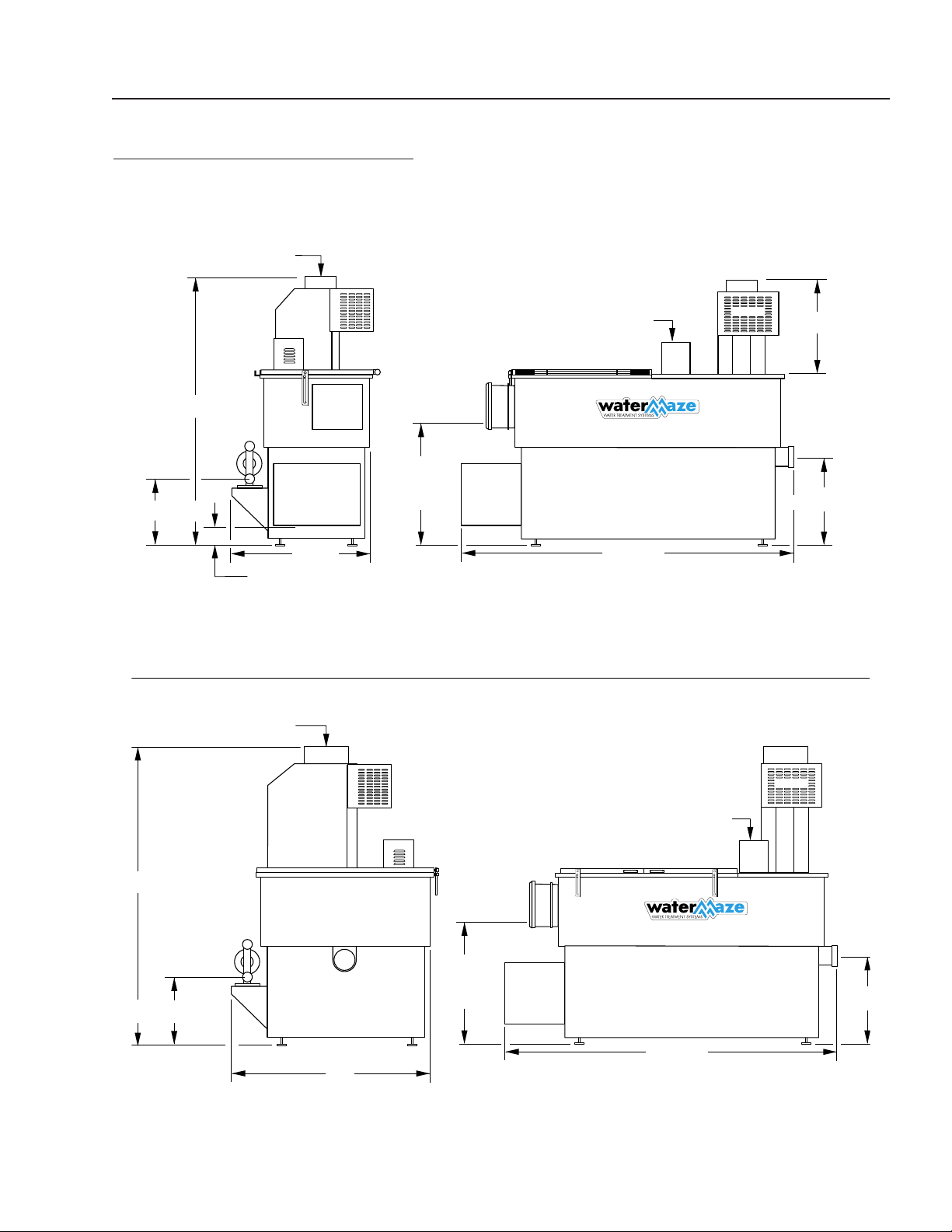
INSTALLATION DIMENSIONS
HBG-15 HBG-30
29" to
Power
Supply
85-1/2"
51"
75"
10" Dia. Exhaust Stack
HBG-15
85-1/2"
21-1/4"
23-1/4"
6" Dia. Exhaust Stack
69"
15" To Pump
3-1/2"
To Gas Supply
42"
HBG-30
14-1/2" to Pump
Float Box
Float Box
29"
To Power
Supply
21-1/4"
18
HBG EVAPORATOR OPERATOR’S MANUAL
HBG • 8.913-990.0-K
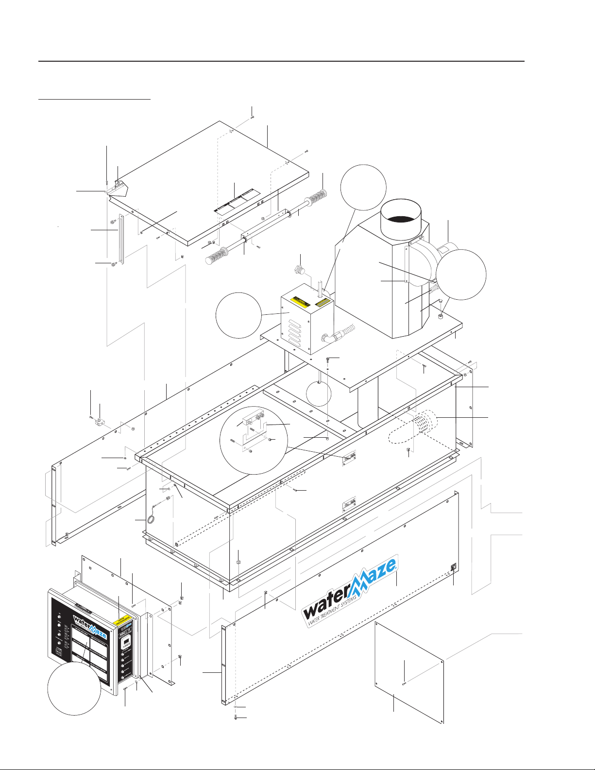
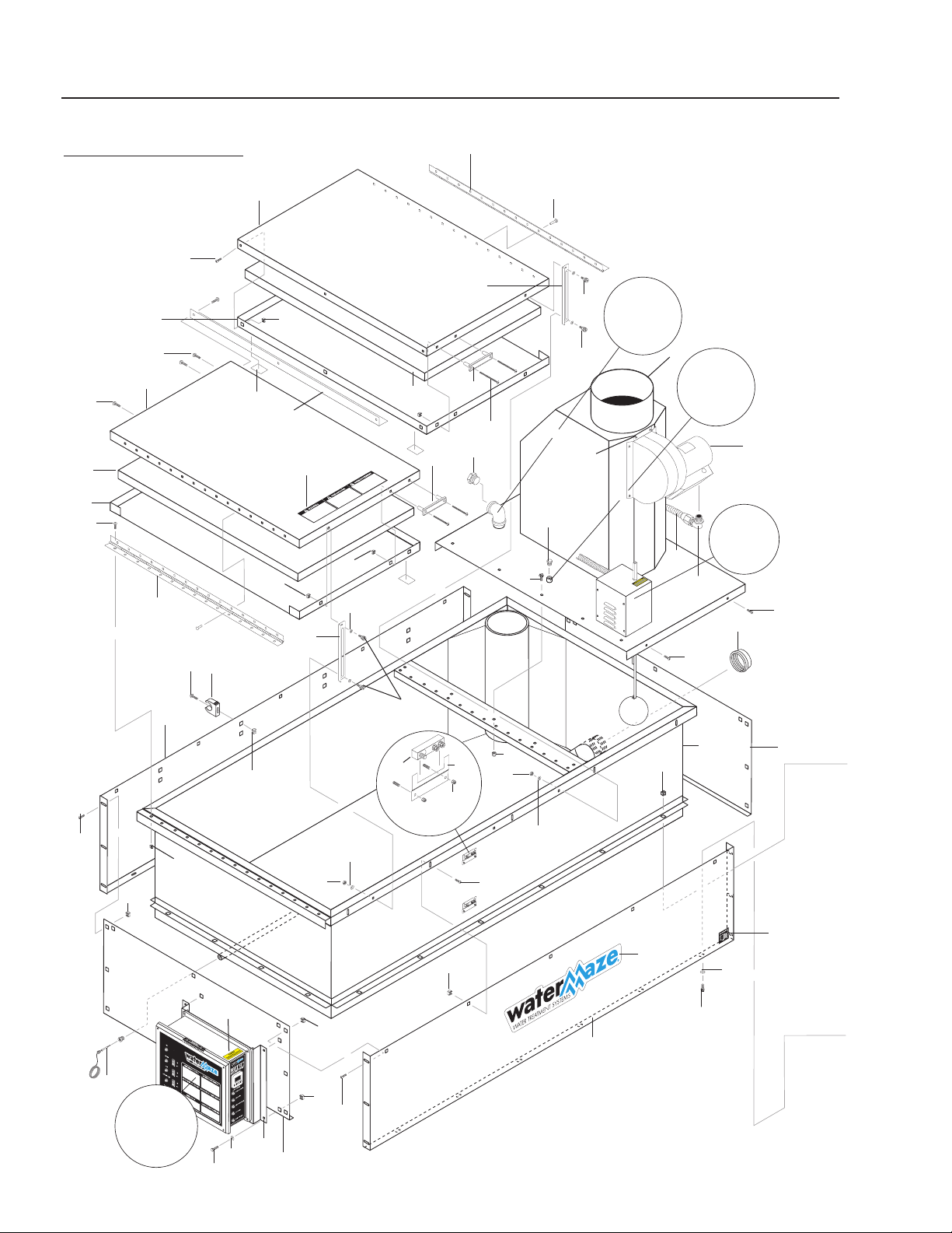
36
EXPLODED VIEW
LEFT SIDE • HBG-15
18
7
5
23
6
4
3
20
42
21
22
24
8
9
45
10
16
44
13
34
2
43
35
1
16
17
10
40
39
15
27
62
57
41
11
56
38
61
10
12
29
48
59
For
Detail
See Control
Panel
For
Detail
See Float
Box Illus.
14
For
Detail
See Air
Defoamer
Option
Illus.
10
58
16
For Detail
See Float
Box Illus
42
36
41
47
16
63
64
65
Thermal
Switch
66
HBG EVAPORATOR OPERATOR’S MANUAL
19
HBG • 8.913-990.0-K
EXPLODED VIEW
RIGHT SIDE • HBG-15
50
54
51
10
16
55
16
10
55
52
26
16
14
49
30
33
32
31
53
19
25, 67
60
19
10
38
37
59
28
Reversed View
of Label
46
27

20
HBG EVAPORATOR OPERATOR’S MANUAL
HBG • 8.913-990.0-K
HBG-15 EXPLODED VIEW
PARTS LIST
ITEM PART NO. DESCRIPTION QTY
1 8.913-200.0 Panel, Front 1
2 8.913-201.0 Panel, Right Side 1
3 8.913-042.0 Bracket, Handle 1
4 8.913-041.0 Handle, Lid 1
5 9.803-049.0 Snap Bushing, 7/8" 2
6 8.706-572.0 Grip, 7/8" Handle 2
7 8.913-043.0 ▲ Lid, Top Inside Shell,
316L SS 1
8.913-045.0 Lid, Hinged Outside Shell 1
8.717-383.0 ▲ Insulation, Rigid Foam,
/Sq Ft, 1/2" x 24" x 33" 6 sf
8.707-404.0 ▲ Pad, HBG Lid, 1/4" 2
8 8.919-841.0 Hinge, 29.5", Door, SS 1
9 8.719-053.0 Rivet, 1/4" x 3/8" Grip,
Blind SS 15
10 8.718-812.0 Screw, Cap 10/32" x 3/4"
BH, HF, SS, Soc 52
11 8.715-192.0 Fan, Draft Inducer, D-3 1
12 8.913-199.0 Panel, Top, 316L SS 1
8.717-738.0 ▲ Flue Adapter, 6" 1
13 8.913-195.0 Tank Assembly, Carbon Steel 1
8.913-196.0 Tank Assembly, 316L SS 1
8.913-197.0 Tank Assembly, AL-6XN SS 1
8.913-178.0 ▲ Shovel, Clean Out 1
14 9.802-792.0 Nut, Cage, 3/8" x 12 Gauge 22
15 8.718-753.0 Screw, 1/4"-20 x 3/4" Phil
PH SS M/S 5
16 9.802-791.0 Nut, Cage, 10/32" x 16 Ga. 55
17 8.706-258.0 Pipe, Cap, 3" Black Pipe 1
8.706-261.0 Pipe, Cap, 3", 316LSS 1
8.707-229.0 ▲Valve, 3" Brass, Ball
(Optional) 1
18 8.900-841.0 Label, Water Maze Logo 1
19 9.800-006.0 Label, Hot/Caliente 2
20 8.900-584.0 Label, Steam Warning 1
21 8.913-176.0 Support, Lid Lock, HBG 1
ITEM PART NO. DESCRIPTION QTY
22 8.718-785.0 Bolt, 3/8" x 3/8" x 3/8"
SCKT 2
23 9.802-776.0 Nut, 5/16" ESNA 1
24 8.718-813.0 Screw, 10/32" x 1/2"
BH SOC, SS 15
25 8.717-099.0 Burner, P-250 AFEP, NG 1
8.717-101.0 Burner, P-250 AFEP, LPG 1
26 9.802-767.0 Screw, 3/8" x 3/4" HH,
NC Whiz 4
27 9.802-448.0 Conduit, Wtr Tight,
Flex 1/2" 12.5 ft
28 8.717-434.0 Insulation, 1" x 2" 2.39 sf
29 8.900-313.0 Label, Assembled in USA 1
30 8.913-198.0 Fire Box W/Insulation 1
31 9.803-138.0 Leveling, Foot Assembly 4
32 9.802-790.0 Nut, 1/2" Hex 4
33 9.803-517.0 Washer, 1/2" Lock 4
34 9.802-721.0 Bolt, 3/8" x 1", NC HH SS 18
35 9.802-808.0 Washer, 3/8" SS Flat 18
36 8.718-980.0 Washer, 5/16" 5
37 8.932-963.0 Label, Liquid Propane 1
8.932-964.0 Label, Natural Gas 1
38 9.802-203.0 Clamp, 1/2" RO, Clip 10
39 9.802-759.0 Screw, 10/32" x 1/2",
BHSOC 4
40 9.802-774.0 Nut, 1/4" ESNA, SS 5
41 8.718-618.0 Bolt, 5/16" x 3/4" 4
42 8.718-903.0 Nut, 5/16" x 12 Gauge, Black 5
43 8.913-204.0 Bracket, Electric Box 1
44 8.913-171.0 Panel, Left Side 1
45 8.913-202.0 Panel, Rear 1
46 8.716-547.0 Connector, 1/2" L/T St 1
47 9.802-517.0 Connector, 1/2 L/T 90° 1
48 8.913-205.0 Lid, Burner Cover 1
49 8.913-203.0 Cover, Burner Assembly 1
50 8.913-253.0 Side Panel, Left, Plenum
Heat Shield 1

HBG EVAPORATOR OPERATOR’S MANUAL
21
HBG • 8.913-990.0-K
HBG-15 EXPLODED VIEW
PARTS LIST (CONTINUED)
ITEM PART NO. DE SCRIP TION QTY
51 8.913-256.0 Cover, Plenum, Heat Shield 1
52 8.913-254.0 Side Panel, Right, Plenum
Heat Shield 1
53 8.913-257.0 Cover, Fan Shield 1
54 8.913-255.0 Lower Cover, Plenum
Heat Shield 1
55 8.717-415.0 Insulation, Blanket - No Foil,
1/2" x 24" /sq ft 6
56 8.718-942.0 Screw, #12 x 3/4", TEK 6
57 8.706-246.0 Plug, 1/4" Allen Countersunk 1
58 8.706-254.0 Plug, 1" Black Hex Head 1
59 9.802-696.0 Nut, 10/32" NF ST ST KEPS 16
60 9.802-781.0 Nut, 3/8" Whiz Loc 4
61 8.718-814.0 Screw, 10/32" x 1-1/4"
BH NC SS 9
62 8.712-175.0 Thermocouple SS Sheath, 34" 1
63 8.913-271.0 Tab, Pinch 2
64 8.712-177.0 Switch, Thermal 2
65 8.718-817.0 Nut, 1/4"-20 Whiz-Loc 4
66 8.900-853.0 Label, Batch Warning 1
67 8.718-197.0 ORIFICE, #22 (.156),
LPG, P-250 Wayne
(LP Option Only) 1
▲ Not Shown
22
HBG EVAPORATOR OPERATOR’S MANUAL
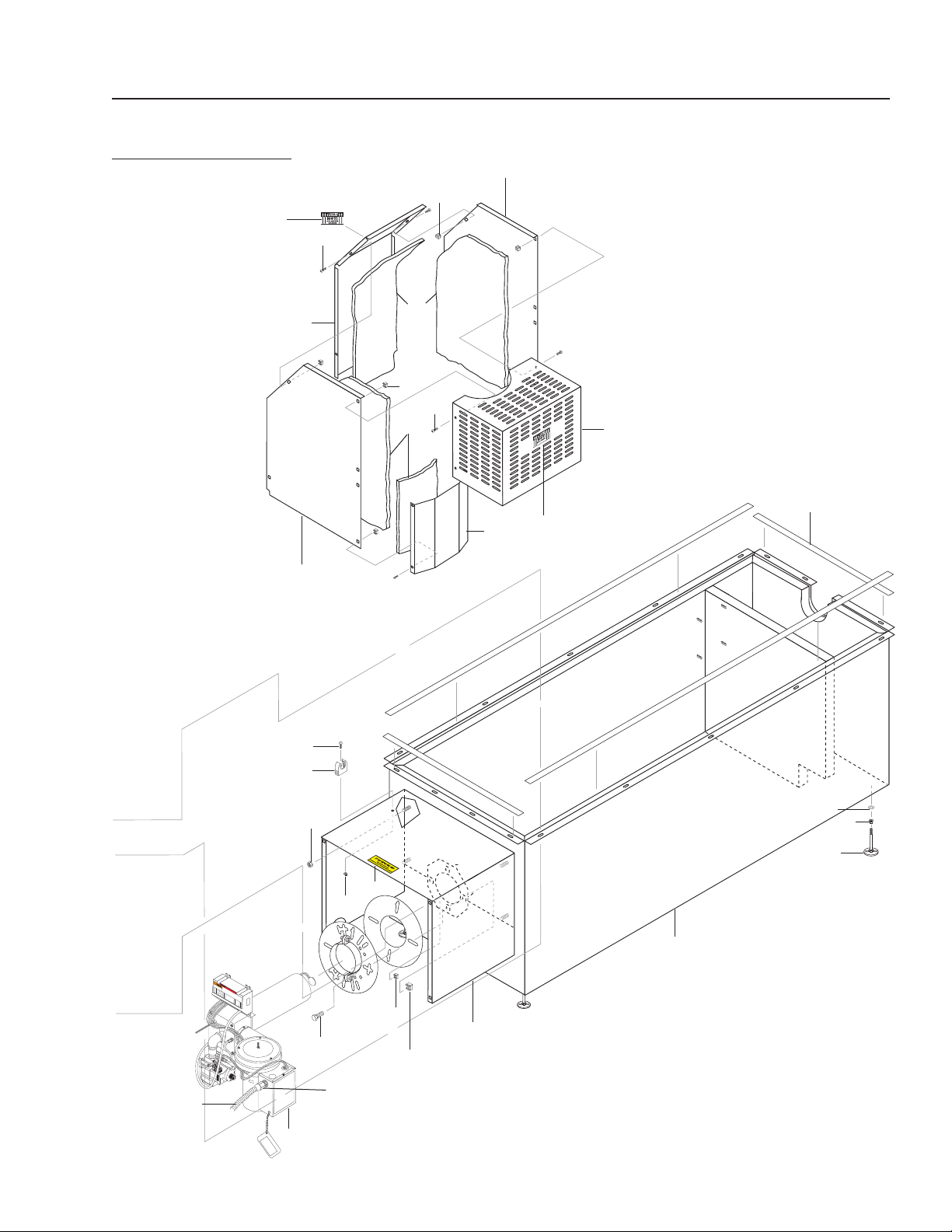
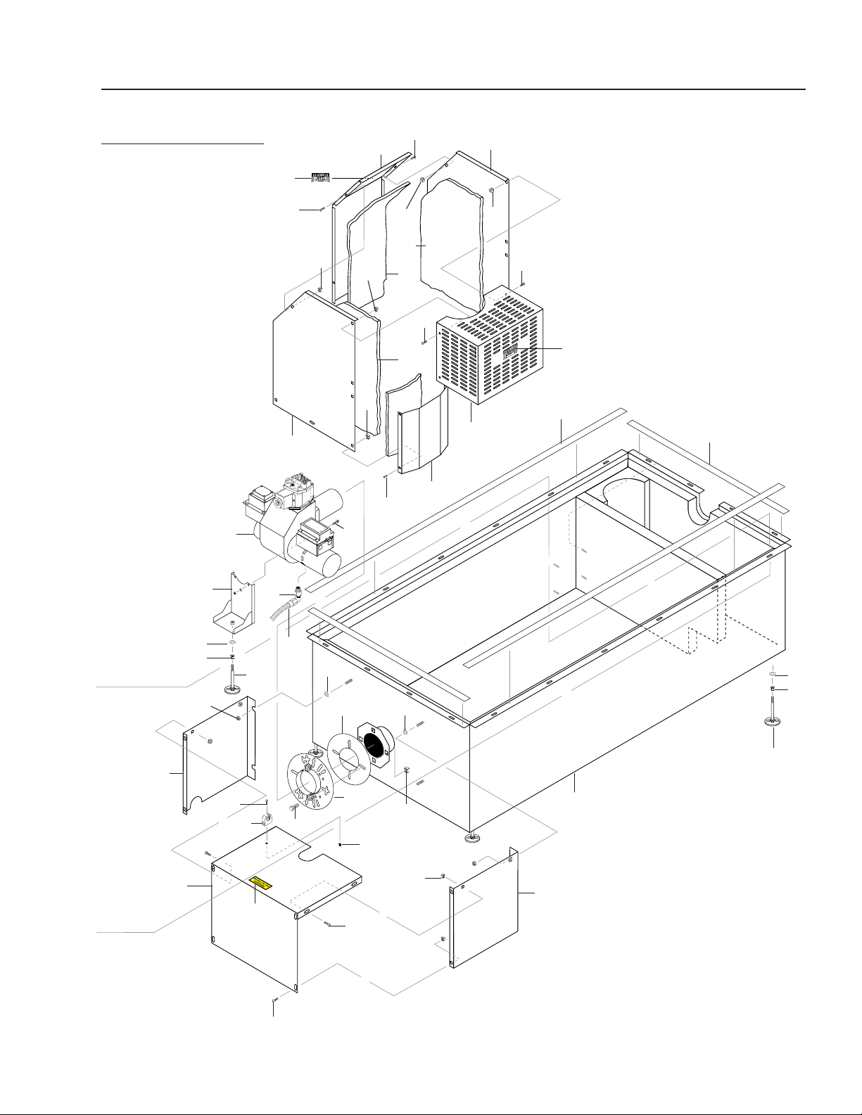
HBG • 8.913-990.0-K
EXPLODED VIEW
LEFT SIDE • HBG-30
1
6
15
11
3
5
31
7
12
2
43
16
14
29
13
33
5
34
For
Detail See
Float Box
Illus.
7
8
10
9
For
Detail See
Control
Panel
Illus.
4
7
31
31
30
36
38
47
49
40
39
43
43
37
29
41
39
40
54
42
1
35
44
35
44
51
29
43
31
52
2
45
43
For
Detail See
Defoamer
Options
Illus.
For
Detail See
Auto Fill
Options
Illus.
65
66
50
64
39
55
67
56
56
63
70
69
57
62
72
71
73
Thermal
Switch
74
HBG EVAPORATOR OPERATOR’S MANUAL
23
HBG • 8.913-990.0-K
EXPLODED VIEW
RIGHT SIDE • HBG-30
26
24
30
29
26
26
23
18
29
43
21
19
29
29
43
28
43
43
22
29
20
43
29
32
48
46
47
37
43
17
53
27
25
27
28
28
46
55
69
58
70
54
54
61
68
60
59
59
68
60
23

24
HBG EVAPORATOR OPERATOR’S MANUAL
HBG • 8.913-990.0-K
HBG-30 EXPLODED VIEW
PARTS LIST
ITEM PART NO. DESCRIPTION QTY
1 8.913-231.0 Lid, Top 2
2 8.919-841.0 Hinge, 29.5", Door, SS 2
3 8.913-176.0 Support, Lid, HBG 1
4 8.913-240.0 Support, Lid, HBG 1
5 8.706-684.0 Handle, Lid SJ 2
6 8.900-584.0 Label, Steam Warning,
Hot Box 1
7 8.718-785.0
Screw, 3/8" x 3/8", SCKT,
SHDR
4
8 8.913-235.0 Guard, Splash 1
9 8.913-242.0 Assy, Top Panel, 316L SS 1
8.717-739.0 ▲ Adapter, Flue, 10" 1
10 8.715-192.0 Fan, Draft Inducer D-3, 1
11 8.913-223.0 Assy, Tank, Carbon Steel 1
8.913-224.0 Assy, Tank 316L SS 1
8.913-225.0 Assy, Tank, AL-6XN 1
8.913-178.0 ▲ Shovel, Clean-Out 1
12 8.913-265.0 Panel, Drain End 1
13 8.913-264.0 Panel, Burner End 1
14 8.913-204.0 Bracket, Electrical Box 1
15 8.913-263.0 Panel, Rear 1
16 8.913-266.0 Panel, Front 1
17 8.913-270.0 Top, Burner Cover 1
18 8.913-250.0 Lower Cover, Plenum Heat
Shield 1
19 8.913-252.0 Cover, Fan Shield 1
20 8.913-249.0 Panel, Right Side 1
21 8.913-248.0 Panel, Left Side 1
22 8.913-267.0 Cover, Plenum 1
23 9.803-138.0 Foot, Leveling 5
24 8.912-120.0 Assy, Fire Box 1
25 8.913-268.0 Wall, Burner Cover, Left 1
26 8.717-100.0 Burner, Wayne, HSG-400 1
27 9.802-759.0 Screw, 10/32" x 1/2" BHSOC 8
28 8.717-415.0 Insulation, Blanket, No-Foil,
1/2" x 24" /sq. ft. 10
29 9.802-791.0 Nut, Cage, 10/32" x 16
Gauge 66
30 9.802-792.0 Nut, Cage, 3/8" x 12 Gauge 24
31 8.718-903.0 Nut, Cage, 5/16" x 12 Gauge 8
ITEM PART NO. DESCRIPTION QTY
32 9.802-767.0 Screw, 3/8" x 3/4" HH NC
Whiz Loc 4
33 9.802-721.0 Bolt, 3/8" x 1" HH/NC, 316
SS 20
34 9.802-808.0 Washer, 3/8" S/S Flat 20
35 8.913-226.0 Lid, Bottom, 16 Gauge 316L 2
36 8.706-258.0 Cap, Pipe, 3" Black Pipe 1
8.706-261.0 Cap, Pipe, 3" 316L SS 1
8.707-229.0 ▲ Valve, 3" Brass (Optional) 1
37 9.802-203.0 Clip, Conduit 12
38 8.900-841.0 Label, Water Maze Logo 1
39 8.718-980.0 Washer, 5/16" Flat 10
40 9.802-776.0 Nut, 5/16" ESNA 2
41 9.802-774.0 Nut, 1/4" ESNA, SS 5
42 8.718-753.0 Screw, 1/4"-20 x 3/4" Phil, PH,
SS, M/S 5
43 8.718-812.0 Screw, Cap, 10-32 x 3/4" 50
44 8.717-383.0 Insulation, Rigid Foam, /Sq Ft
1/2" x 23.5" x 35"
(Note: 6 Sq Ft/ Lid) 12 sf
45 8.719-053.0 Rivet, 1/4" x 3/8" Grip,
Blind SS 30
46 9.800-006.0 Label, Hot/Caliente 2
47 9.802-696.0 Nut, 10-32, SS 31
48 9.802-781.0 Nut, 3/8" Whiz Loc 4
49 8.712-175.0 Thermocouple, SS Sheath,
34" 1
50 8.718-813.0 Screw, 10-23 x 1/2" BH,
SOC SS 30
51 8.718-729.0 Screw, 1/4"-20 x 2" SHCS,
Zinc 4
52 9.802-793.0 Nut, Cage, 1/4" x 16 Gauge 8
53 8.913-269.0 Wall, Burner Cover, Right 1
54 9.802-807.0 Washer 3/4" Flat 6
55 8.718-618.0 Bolt, 5/16" x 3/4" NC 6
56 8.718-814.0 Screw, 10/32" x 1-1/4" BH
SOC SS 8
57 8.718-942.0 Screw #12 x 3/4" TEK 6
58 8.913-258.0 Assy Bracket, Burner Support 1
59 8.717-434.0 Insulation, 2" x 1", 3.1 sf
60 9.802-790.0 Nut, 1/2" Hex NC 5
61 8.932-964.0 Label, Natural Gas 1

HBG EVAPORATOR OPERATOR’S MANUAL
25
HBG • 8.913-990.0-K
HBG-30 EXPLODED VIEW
PARTS LIST (CONT)
ITEM PART NO. DESCRIPTION QTY
62 8.707-404.0 Pad, Hot Box Lid,
1/4 Neoprene 4
63 8.706-246.0 Plug, 1/4" Allen Countersunk 1
64 8.706-254.0 Plug, 1" Black Hex Head 1
65 9.802-760.0 Screw, 1/4" x 1/2" BH SOC 4
66 9.802-708.0 Screw 5/16" -18 x 3/4" 2
67 8.900-313.0 Label, Assembled in USA 1
68 9.803-517.0 Washer 5
69 9.802-517.0 Connector, 1/2" L/T 90° 2
70 9.802-448.0 Conduit WTR Tight
Flex 1/2 15 ft.
71 8.913-271.0 Tab, Pinch 2
72 8.712-177.0 Switch, Thermal 2
73 8.718-817.0 Nut, 1/4"-20 Whiz Loc 4
74 8.900-853.0 Label, Batch Warning 1
▲ Not Shown
26
HBG EVAPORATOR OPERATOR’S MANUAL
HBG • 8.913-990.0-K
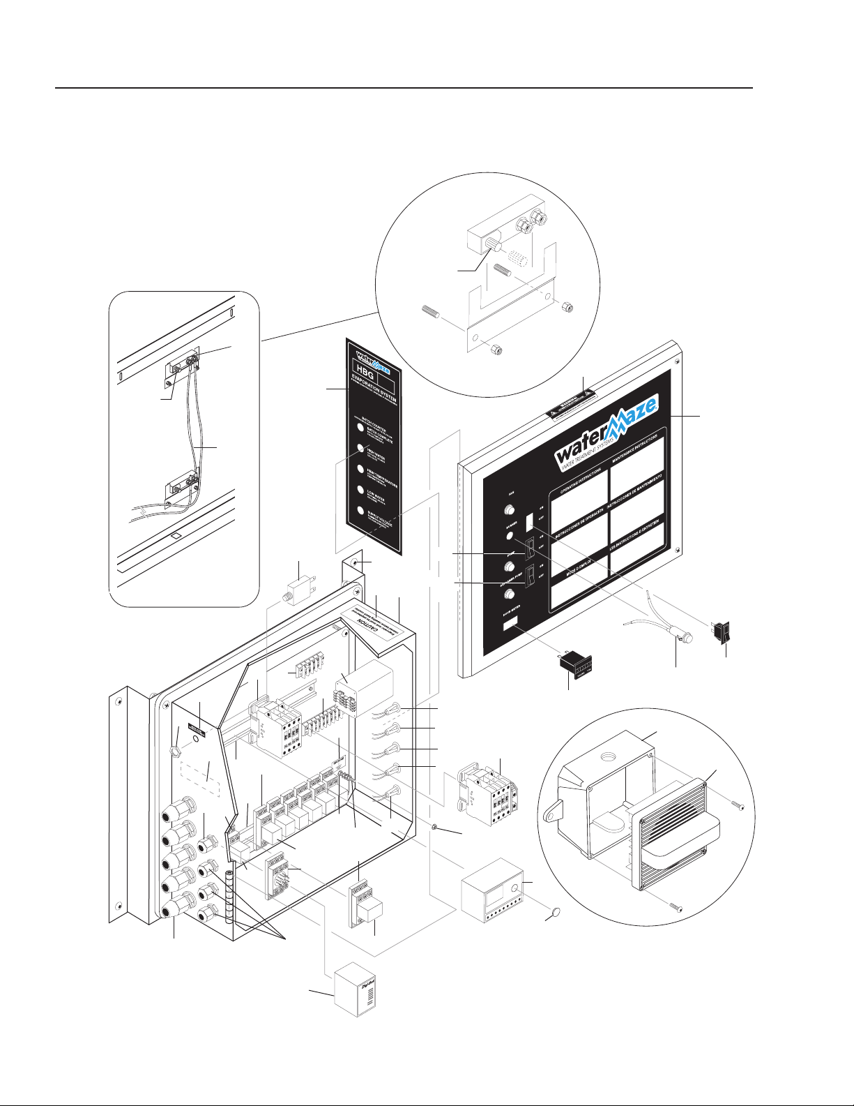
89139900-3
1
14
13
18
21
21
12
19
18
3
9
4
7
5
6
11
16
15
2
29
20
17
27
28
Reversed
View Of Label
35, 36, 37
10
12
8
26
5
7
6
23
31
32
33
24
24
34
25
Note:
Rotate
Switch Dial
to Highest
Setting
To
Control
Panel
Trim Dial to
Fit Behind
Side Panel
Thermal Switch
42
41
43
44
Remote Strobe/Horn
(To be Mounted by
Customer)
22
46
45

HBG EVAPORATOR OPERATOR’S MANUAL
27
HBG • 8.913-990.0-K
ITEM PART NO. DESCRIPTION QTY
1 9.802-453.0 Switch, Curvette 1
2 8.716-091.0 Switch, Momentary Push 1
3 8.716-211.0 Relay, 120V, 4PDT 1
4 8.716-212.0 Base, Relay, 120V, 4PDT 1
5 9.802-457.0 Din Rail, 35MM 23"
8.718-936.0 ▲ Screw #8 x 1/2" Tek,
Sq Head SS 4
8.718-959.0 ▲ Washer #10 Flat SS 4
6 9.802-468.0 Relay, 120V, 2PDT 5
(Auto Fill Option) 2
7 9.802-467.0 Base, Relay, 2PDT 5
(Auto Fill Option) 2
8 8.716-237.0 Counter, Red Lion 1
9 8.716-251.0 Timer, Variable Time 1
10 8.716-281.0 Box, Plastic, 14" x 16" x 6-3/4"
w/Hinged Lid 1
11 9.802-492.0 Block, Terminal, 8 Pole 1
8.718-898.0 ▲ Nut Cage, 8/32" x 16 ga 2
9.802-749.0 ▲ Screw 8/32" x 3/4" 2
12 8.724-264.0 Contactor, 15 Amp 1
Contactor (Auto Fill Option) 1
13 9.802-283.0 Hour Meter 1
14 8.754-117.0 Hi Limit Control
500°F 1
15 8.716-547.0 Connector, 1/2" LT 3
(Options) 2
16 9.802-515.0 Strain Relief, STRT, LQ Tite 1
17 9.802-514.0 Strain Relief, STRT, LQ
Tite Sm (Options) 3
18 9.802-455.0 Light, Indicator, Green, 125V 2
(Auto Fill Option) 1
(Air Defoamer Option) 1
19 8.716-408.0 Light, Amber, 125V
(Auto Fill Option) 1
8.716-409.0 Light, Blue 125V 1
20 9.803-540.0 Light, Blue, 14V 1
21 8.716-409.0 Light, Blue, 125V 2
CONTROL PANEL
HBG-15, HBG-30 Parts List
ITEM PART NO. DESCRIPTION QTY
22 9.802-491.0 Block, Terminal, 8 Pole 1
23 8.716-252.0 Base Timer, IDEC Socket 1
24 8.716-052.0 Switch Curvette ON-OFF-ON
(Auto Fill Option) 1
(Air Defoamer Option) 1
25 8.913-206.0 Standoff Electrical Box 1
9.802-759.0 ▲ Screw 10/32" x1/2" 4
9.802-695.0 ▲ Nut, 10/32" Keps 4
26 8.900-536.0 Label, Manual Reset Temp
Switch 1
27 9.800-016.0 Label, Disconnect
Power Supply 1
28 8.900-585.0 Label, Control Box Front 1
29 8.900-586.0 Label, Control Box, Side 1
30 8.670-187.0 ▲ Switch, Float N/O
(Auto Fill Option) 1
31 9.800-040.0 Label, Ground 1
32 8.716-460.0 Terminal, Gounding Lug 1
33 8.718-730.0 Screw,
10/22" x 2-1/2"
Rnd Hd 1
34 9.802-695.0 Nut, 10/32" Keps 5
35 8.718-817.0 Nut, 1/4"-20 Hex Whiz
Loc SS 4
36 8.718-603.0 Bolt, 1/4" x 3/4" NC, HH,SS 4
37 8.718-965.0 Washer, 1/4" SS Flat 4
38 8.900-234.0 ▲ Label, HBG 1
39 8.940-157.0 ▲ Label 15 (HBG-15) 1
8.900-401.0 ▲ Label 30 (HBG-30) 1
40 8.753-351.0 ▲ Channel 1" Gray,
w/Cover 1.25 ft
41 8.900-853.0 Label, Caution Empty Tank 1
42 8.716-004.0 Wire, Nickel Hinge, 12 Ga. 20 ft.
43 8.752-970.0 Black Box 1
44 8.752-143.0 Strobe Light w/Horn 1
45 8.706-738.0 Plug, 3/4" Hole 1
46 8.923-972.0 Label, Caution
Thermostat HBG 1
▲ Not Shown
28
HBG EVAPORATOR OPERATOR’S MANUAL
HBG • 8.913-990.0-K
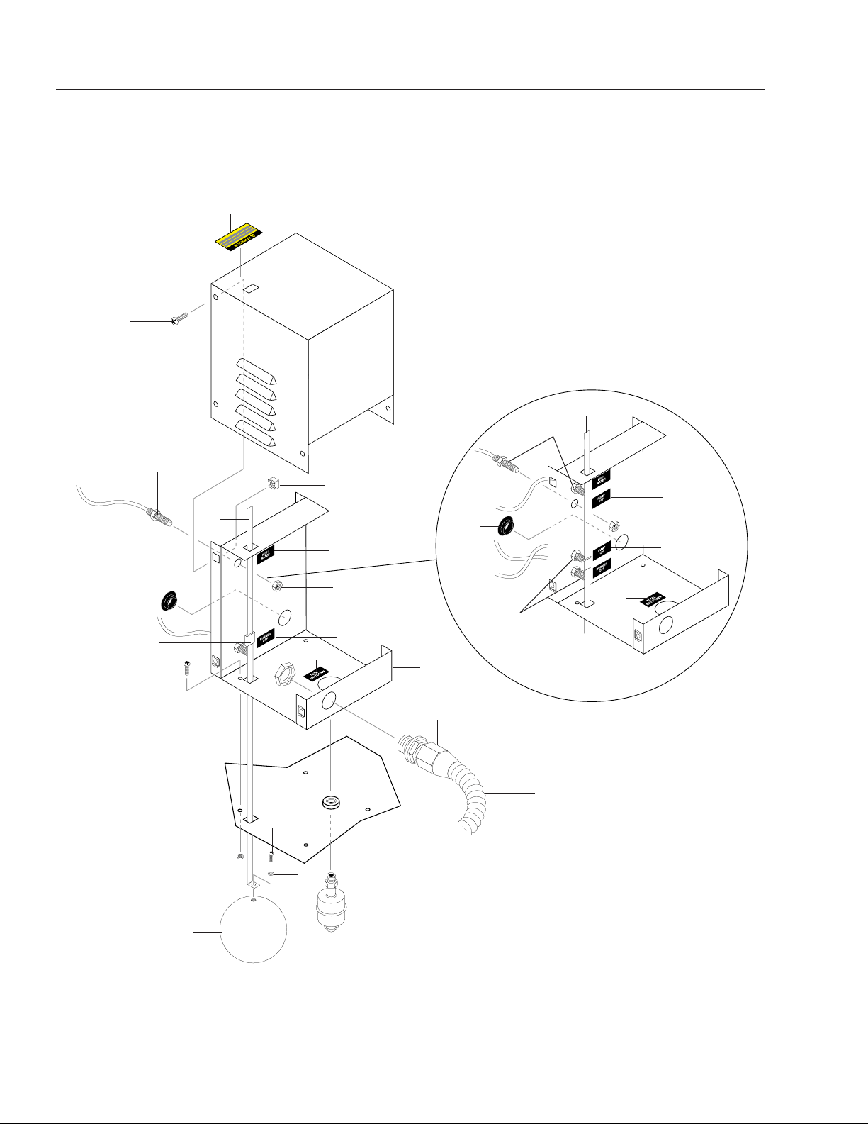
FLOAT ASSEMBLY
EXPLODED VIEW
1
2
2
4
6
5
7
8
9
10
Tank Lid
Float
Float
12
11
2
Auto Fill Option
3
22
18
19
21
15
16
14
13
Standard
10
18
19
20
21
23
17
17
23

HBG EVAPORATOR OPERATOR’S MANUAL
29
HBG • 8.913-990.0-K
FLOAT ASSEMBLY
PARTS LIST
ITEM PART NO. DESCRIPTION QTY
1 9.804-120.0 Magnet 1
8.731-134.0 ▲ Screw, 4 x 40 1
8.718-847.0 ▲ Nut, 4 x 40 1
2 9.804-119.0 Switch, Magnetic N/C 2
3 9.804-118.0 Switch, Magnetic N/O
(Auto Fill Option) 2
4 9.802-791.0 Nut, Cage, 10/32" 6
5 8.718-813.0 Screw, 10/32" SS 4
6 9.802-696.0 Nut, 10/32" Keps, SS 4
7 8.913-262.0 Box, Float 1
8 8.913-243.0 Lid, Float Box 1
9 8.900-582.0 Label, Keep Float Free 1
10 8.913-259.0 Float Rod, Long 1
11 8.712-132.0 Float, 3-1/2" Ball, Steel
316SS 1
12 8.716-294.0 Switch, Liquid Level, M-500 1
13 8.718-978.0 Washer, 1/4" Split Ring
Lock SS 1
14 9.802-760.0 Screw, 1/4" x 1/2" BH SOC 1
15 9.802-517.0 Connector, 1/2" L/T 90° (15D) 1
8.716-547.0 Connector, 1/2" L/T St (30D) 1
16 9.802-448.0 Conduit, WTR Tight Flex
(15D) 6 ft.
(30D) 8.5 ft.
17 9.802-103.0 Bushing, Snap 5/8" 1
18 8.900-328.0 Label, High Water 1
19 8.900-327.0 Label, Pump Off
(Auto Fill Option) 1
20 8.900-326.0 Label, Pump On
(Auto Fill Option) 1
21 8.900-330.0 Label, Burner Off 1
22 9.802-759.0 Screw, 10/32" x 1/2 Black 6
23 8.900-329.0 Label, Total Shutdown 1
▲ Not Shown
30
HBG EVAPORATOR OPERATOR’S MANUAL
HBG • 8.913-990.0-K
14
6
17
36
8
33
10
12
11
12
11
19
18
11
13
7
9
1
2
3
15
4
17
16
5
19
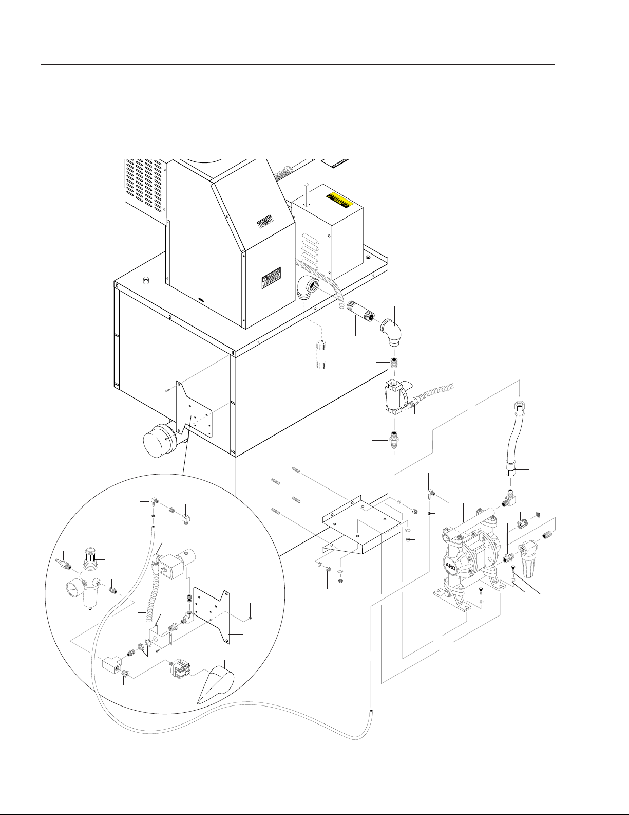
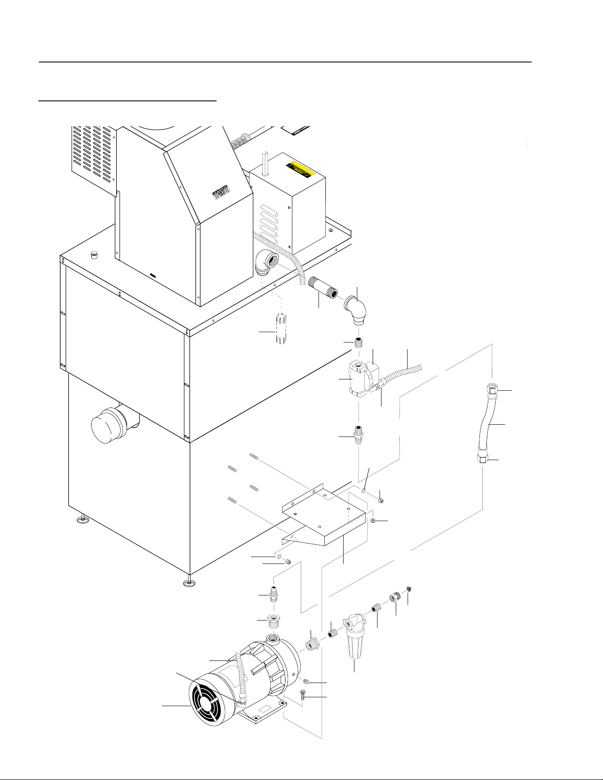
HBG OPTIONS
AIR AUTO FILL EXPLODED VIEW
Reversed View
of Tank Sensor
Assembly
38
32
21
22
43
23
24
42
16
26
27
39
45
30
29
23
40
44
28
40
25
41
39
20
37
21
37
22
35
31
34
35

HBG EVAPORATOR OPERATOR’S MANUAL
31
HBG • 8.913-990.0-K
HBG OPTIONS
AIR AUTO FILL PARTS LIST
ITEM PART NO. DESCRIPTION QTY
1 8.706-024.0 Nipple, 1" x 4", Black Pipe 1
2 9.802-028.0 Elbow, 1" x 3/4", Reducing Blk 1
3 8.716-689.0 Solenoid Coil, 120V 1
4 8.706-899.0 Nipple, 3/4" JIC x 3/4" Pipe 1
5 9.802-261.0 Hose, 3/4" Push-On 1.66 ft.
6 9.802-132.0 Elbow, 3/4" JIC x 1/2", 90° 1
7 8.715-278.0 Pump, Air Diaphragm, 1/2"
Poly 1
8 9.804-016.0 Filter Screen Washer,
Garden Hose / 30Mesh 1
9 8.706-023.0 Nipple, 1" x 4", 316L SS 1
10 8.709-179.0 Filter, Inlet 1
11 8.718-980.0 Washer, 5/16" Flat, SAE 8
12 9.802-710.0 Bolt, 5/16" x 1", NC HH 4
13 8.706-881.0 Nipple, 3/4" Pipe x 1/2" Pipe 1
14 8.913-040.0 Bracket, Pump Support, Black 1
15 8.716-690.0 Valve, Solenoid, Parker 1
16 9.802-448.0 Conduit, Flex, Water Tight 16 ft.
17 9.802-152.0 Swivel, 3/4" SAE Female,
Push-On 2
18 9.802-776.0 Nut, 5/16" ESNA, NC 4
19 9.802-779.0 Nut, 3/8" ESNA 4
20 9.802-254.0 Hose, 1/4" Push-on 2.66 ft
21 6.390-126.0 Clamp, Hose, .46-, .54 ST 2
22 8.706-958.0 Barb, Hose,
1/4" Barb x 1/4" Pipe 2
23 8.706-827.0 Elbow 1/4" Street 2
24 8.716-691.0 Valve, Solenoid Parker 1
25 8.706-910.0 Bushing, 1/4" x 1/8" Pipe 1
26 8.707-177.0 Nipple, 1/4" Male, Air 1
27 8.707-331.0 Regulator, Air w/Filter 1/4" Ga 1
28 8.716-413.0 Pressure Switch Barksdale 1
29 8.716-427.0 Boot, Red Tri Delta Switches 1
30 8.913-177.0 Bracket, Defoamer Pump 1
31 8.912-531.0 Support, Metering Valve 1
32 8.718-812.0 Screw 10/32" x 3/4" BH SOC 2
33 8.706-799.0 Nipple 3/4" Close 1
34 9.802-017.0 Nipple, 3/4" Close Black 1
35 9.802-517.0 Connector 1/2-L/T 90° Black 1
36 8.706-970.0 Swivel,
3/4" Fem HS x 3/4"
Fem
1
37 9.802-807.0 Washer, 3/8 SAE Flat 4
ITEM PART NO. DESCRIPTION QTY
38 8.900-210.0 Label, Warning 100 PSI Air
Pressure 1
39 8.706-780.0 Nipple, 1/4 Hex 3
40 8.706-999.0 Connector, 1/4" Anchor 1
41 8.706-841.0 Tee 1/4" Female Pipe 1
42 9.802-533.0 Solenoid Coil 120V 1
43 8.706-996.0 Adapter 1/4" x 1/4" 1
44 9.802-759.0 Screw 10/32" x 1/2" Blk 4
45 9.802-696.0 Nut 10/32" Keps SS 4
46 9.802-422.0 ▲ Cord Service SEO16-2 11 ft.
▲ Not Shown
32
HBG EVAPORATOR OPERATOR’S MANUAL
HBG • 8.913-990.0-K
HBG OPTIONS
AIR DEFOAMER ASSEMBLY EXPLODED VIEW
Anti-Foam
Metering
Pump
Exterior View of
Defoamer Assy
Reversed
View of Tank
Sensor
Foam
Injector
Interior View
of Spray Assy
(Enlarged)
1
10
22
15
16
27
6
11
4
7
19
14
20
31
23
21
2
36
3
9
8
4
10
5
14
18
25
34
29
33
17
10
26
12
30
13
27
28
32
29
28
27
Anti-Foam
Metering
Pump
24

HBG EVAPORATOR OPERATOR’S MANUAL
33
HBG • 8.913-990.0-K
HBG OPTIONS
AIR DEFOAMER ASSEMBLY PARTS LIST
ITEM PART NO. DESCRIPTION QTY
1 8.712-155.0 Gauge, Pressure, 0-10 PSI 1
2 9.802-254.0 Hose, 1/4" Push-On 3
3 8.711-453.0 Nozzle Only, 1/4" Meg 1
4 6.390-126.0 Clamp, Hose, .46-, .54 ST 2
5 8.749-860.0 Check Valve, PVC,1/8" MP, 1
6 8.707-341.0 Valve, Inline Metering 1
7 8.706-958.0 Hose Barb, 1/4" Barb x 1/4"
Pipe, 90° 1
8 8.706-955.0 Hose Barb, 1/4" Barb x 1/8"
MP, 90° 1
9 8.706-857.0 Tee, 1/8" Street 1
10 8.706-827.0 Elbow, 1/4" Street 3
11 8.706-163.0 Elbow, 1/4" Male, Pipe 1
12 8.716-691.0 Valve, Solenoid, Parker 1
13 9.802-448.0 Conduit, Flex Water Tight 10 ft.
14 8.706-910.0 Bushing, 1/4" x 1/8" Pipe 2
15 8.707-177.0 Nipple, 1/4" Mal Air 1
16 8.707-331.0 Regulator, Air w/ Filter,
1/4" Ga 1
17 8.706-777.0 Nipple, 1/4" Close 1
18 8.705-971.0 Nipple, 1/4 " Close,
304 Stainless 1
19 8.716-413.0 Pressure Switch, Barksdale 1
20 8.716-427.0 Boot, Red, Tri Delta Switches 1
ITEM PART NO. DESCRIPTION QTY
21 8.913-177.0 Bracket, Defoamer Pump
Mount 1
22 8.912-531.0 Support, Metering Valve 1
23 8.718-812.0 Screw, 10/32" x 3/4" BH SOC 2
24 8.919-139.0 Pump, Peristaltic, 8-45 gpd,
Sekokem 1
25 8.706-165.0 Elbow, 1/4", 45°, 316L SS 1
26 9.802-517.0 Connector 1/2" L/T 90°
Black 1
27 8.706-780.0 Nipple 1/4" Hex 3
28 8.706-999.0 Connector 1/4" Anchor 1
29 8.706-841.0 Tee 1/4" Female Pipe 2
30 9.802-533.0 Solenoid Coil, 120V 1
31 8.718-941.0 Screw, #10 x 5/8", Tek 2
32 9.802-759.0 Screw 10/32" x 1/2" 4
33 9.802-696.0 Nut, 10/32 Keps SS 4
34 8.900-229.0 Label, 2 PSI 1
35 9.802-422.0 ▲ Cord Service SEO 16-2 11 ft.
36 8.711-737.0 Tubing, 1/8" ID, Norprene 2.5 ft.
37 9.802-525.0 ▲ Locknut, 1/2" 1
38 8.900-210.0 ▲ Label, Warning 100 PSI
Air Pressure 1
▲ Not Shown
34
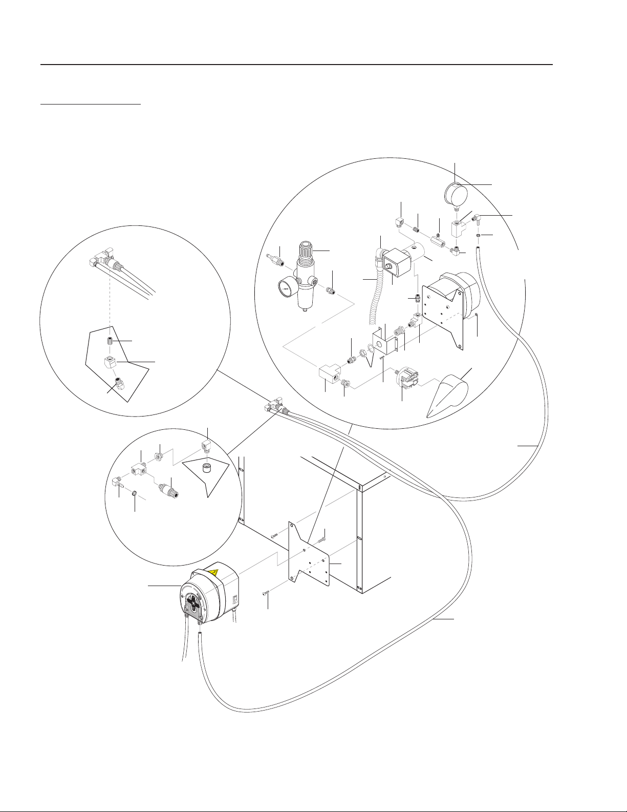
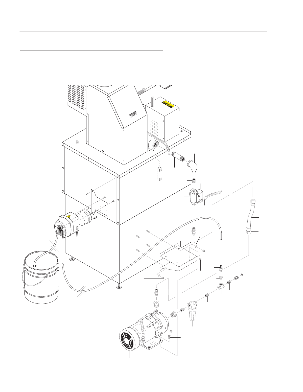
HBG EVAPORATOR OPERATOR’S MANUAL
HBG • 8.913-990.0-K
HBG ELECTRIC AUTO FILL
EXPLODED VIEW
1
2
3
4
5
6
9
10
11
10
24
23
22
23
24
9
12
18
17
15
15
14
16
21
8
13
7
19
8
7
20

HBG EVAPORATOR OPERATOR’S MANUAL
35
HBG • 8.913-990.0-K
HBG ELECTRIC AUTO FILL
EXPLODED VIEW PARTS LIST
ITEM PART NO. DESCRIPTION QTY
1 8.706-023.0 Nipple, 1" x 4" 316L SS 1
2 8.706-024.0 Nipple, 1" x 4" Black Pipe 1
3 9.802-028.0 Elbow, 1" x 3/4 Reducing
Black 1
4 9.802-017.0 Nipple, 3/4" x Close Black 1
5 8.716-690.0 Valve, Solenoid Parker 1
6 8.716-689.0 Solenoid Coil, 120V 1
7 9.802-517.0 Connector, 1/2" L/T 90° 2
8 9.802-448.0 Conduit, WTR Tight Flex 16 ft.
9 8.706-899.0 Nipple, 3/4" JIC x 3/4 Pipe 2
10 9.802-152.0 Swivel, 3/4" SAE Fem,
Push-on 2
11 9.802-261.0 Hose, 3/4" Push-on 1.33 ft.
12 8.706-929.0 Bushing, 1" x 3/4" Barstock 1
13 8.715-382.0 Pump, 1/2 HP 115/230V,
5 Cyclone 1
14 8.706-930.0 Bushing, 1-1/4 x 3/4" Brass 1
15 8.706-799.0 Nipple, 3/4" Close 2
16 8.709-179.0 Strainer, 3/4" x 20 Mesh 1
17 8.706-970.0 Swivel, 3/4" Fem HS x 3/4"
Fem 1
18 9.804-016.0 Filter Screen Washer,
Garden Hose / 30Mesh 1
19 8.706-865.0 Plug, 1/4" Countersunk 1
20 8.913-040.0 Bracket, Pump Support 1
21 9.802-767.0 Screw, 3/8" x 3/4" HH NC
Whiz 4
22 9.802-781.0 Nut, 3/8" Flange Whiz 4
23 8.725-395.0 Nut, 3/8 ESNA NC 4
24 9.802-807.0 Washer, 3/8" Flat 4
25 9.802-203.0 ▲ Clamp, 1/2" Ro-Clip 4
▲ Not Shown
36
HBG EVAPORATOR OPERATOR’S MANUAL
HBG • 8.913-990.0-K
HBG ELECTRIC AUTO FILL ANTI FOAM KIT
EXPLODED VIEW
1
2
3
4
5
6
7
8
9
10
11
10
31
33
29
24
23
22
18
17
15
26
27
15
15
14
19
16
24
23
9
12
8
7
13
20
21
30
28

HBG EVAPORATOR OPERATOR’S MANUAL
37
HBG • 8.913-990.0-K
HBG ELECTRIC AUTO FILL ANTI FOAM KIT
EXPLODED VIEW PARTS LIST
ITEM PART NO. DESCRIPTION QTY
1 8.706-023.0 Nipple, 1" x 4" 316L SS 1
2 8.706-024.0 Nipple, 1" x 4" Black Pipe 1
3 9.802-028.0 Elbow, 1" x 3/4"
Reducing Black 1
4 9.802-017.0 Nipple, 3/4" x Close, Black 1
5 8.716-690.0 Valve, Solenoid Parker 1
6 8.716-689.0 Solenoid, Coil 120V 1
7 9.802-517.0 Connector, 1/2" L/T 90° 2
8 9.802-448.0 Conduit, WTR Tight, Flex 16 ft.
9 8.706-899.0 Nipple, 3/4" JIC x 3/4" Pipe 2
10 9.802-152.0
Swivel, 3/4" SAE Fem,
Push-On
2
11 9.802-261.0 Hose, 3/4" Push-on 1.33 ft
12 8.706-929.0 Bushing, 1" x 3/4" Barstock 1
13 8.715-382.0 Pump, 1/2 HP, 115/230V,
5 Cyclone 1
14 8.706-930.0 Bushing, 1-1/4" x 3/4" Brass 1
15 8.706-799.0 Nipple, 3/4" Close 3
16 8.709-179.0 Strainer, 3/4" x 20 Mesh 1
17 8.706-970.0 Swivel, 3/4" Fem HS x 3/4"
Fem 1
18 9.804-016.0 Filter Screen Washer,
Garden Hose / 30Mesh 1
19 8.706-865.0 Plug, 1/4" Countersunk 1
20 8.913-040.0 Bracket, Pump Support 1
ITEM PART NO. DESCRIPTION QTY
21 9.802-767.0
Screw, 3/8" x 3/4" HH,
NC Whiz
4
22 9.802-781.0 Nut, Flange Whiz 4
23 8.725-395.0 Nut, 3/8 ESNA NC 4
24 9.802-807.0 Washer, 3/8" Flat 4
25 9.802-203.0 ▲ Clamp, 1/2" Ro-Clip 4
26 8.706-846.0 Tee 3/4" Female Pipe, Brass 1
27 8.706-921.0 Bushing, 3/4" x 1/8" Pipe 1
28 8.718-941.0 Screw, #10 x 5/8" Tek 2
29 8.749-860.0 Check Valve ,PVC 1/8" MP 1
30 8.711-737.0 Tubing, 1/8" ID, Norprene 3 ft.
31 8.919-139.0 Pump, Peristaltic 8-45 gpd,
Sekokem 1
32 9.802-525.0 ▲ Locknut, 1/2" 1
33 8.913-177.0 Bracket, Defoamer
Pump Mount 1
▲ Not Shown
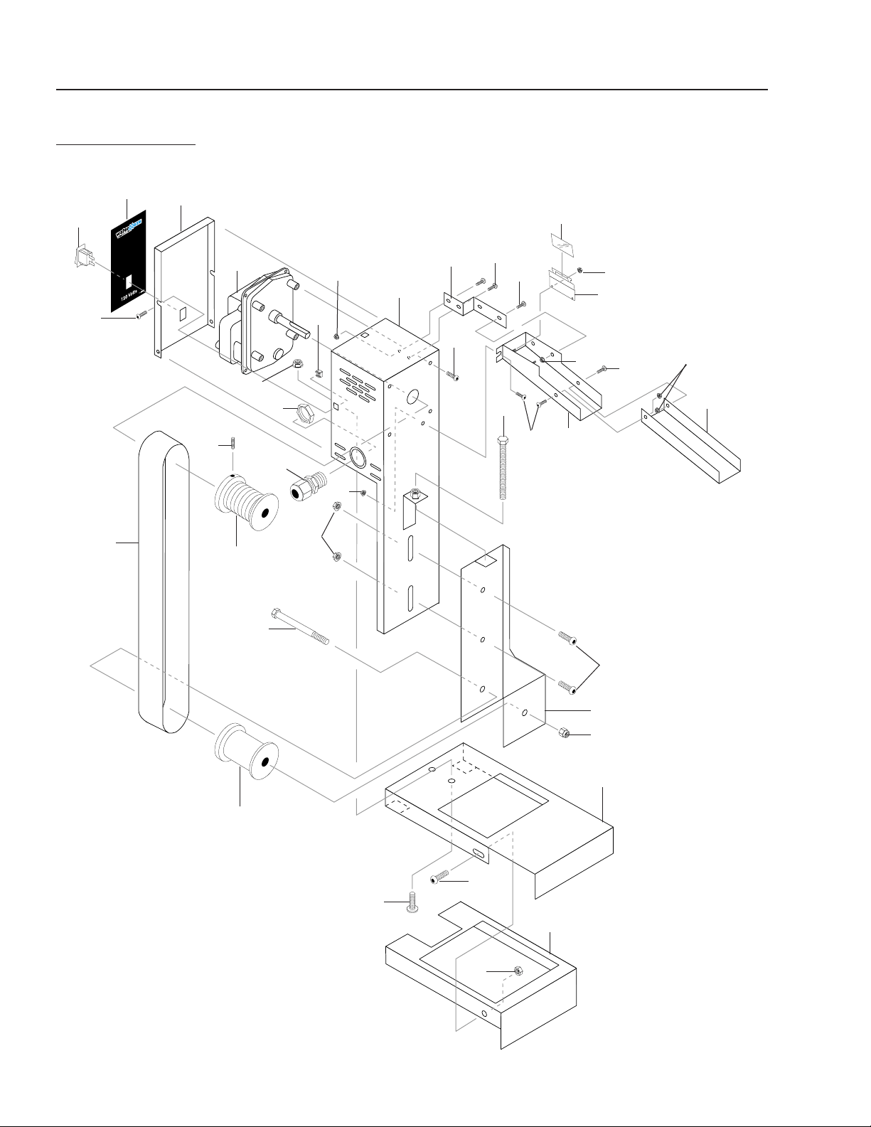
38
HBG EVAPORATOR OPERATOR’S MANUAL
HBG • 8.913-990.0-K
HBG OPTIONS
OIL SKIMMER ASSEMBLY (8.903-741.0) EXPLODED VIEW
16
15
5
17
15
21
13
12
7
23
6
15
15
8
15
17
17
10
11
4
18
23
2
14
1
3
15
28
25
18
24
27
26
22
18
19
23
9
20
23

HBG EVAPORATOR OPERATOR’S MANUAL
39
HBG • 8.913-990.0-K
ITEM PART NO. DESCRIPTION QTY
1 8.706-750.0 Belt, Oil Skimmer, Urethane 1
2 8.719-982.0 Spool, Lower (316SS) 1
3 8.719-983.0 Spool, Upper (316SS) 1
4 8.913-290.0 Frame, Idler Pulley
(316SS) 1
5 8.913-288.0 Assy, Frame/Elec Box
(316SS) 1
6 8.931-138.0 Assy, Oil Ramp (316SS) 1
7 8.913-283.0 Extension, Oil Ramp,
(316SS) 1
8 8.719-980.0 Holder, Plastic Blade 1
9 8.706-751.0 Blade, Oil Skimmer, Plastic 1
10 8.913-190.0 Bracket, Lower 1
11 8.913-188.0 Assy, Oil Skimmer Bracket
(316SS) 1
12 8.913-277.0 Lid, Motor Cover (316SS) 1
13 8.715-159.0 Motor, Belt Skimmer 1
14 8.718-638.0 Bolt, 5/16" x 3-1/2" NC 1
15 8.718-813.0 Screw, 10/32" x 1/2" BHSOC
(316SS) 13
16 8.731-131.0 Bolt, 1/4"-20 x 1-3/4",
NC Tap SS 1
HBG OPTIONS
OIL SKIMMER PARTS LIST
ITEM PART NO. DESCRIPTION QTY
17 8.718-753.0 Screw, 1/4"-20 x 3/4" PHIL BH
SS M/S (316SS) 6
18 8.718-882.0 Nut, 1/4" -20, NC Keps, SS 6
19 9.802-777.0 Nut, 5/16" Esna NC SS 1
20 9.802-785.0 Nut, 8/32" KEPS 2
21 9.802-791.0 Nut, Cage, 10/32" x
16 Gauge 2
22 8.731-137.0 Screw, 1/4" x 3/8" SOC, Set,
Blk 1
23 9.802-696.0 Nut, 10/32" Keps, SS 7
24 8.913-293.0 Bracket, Ramp Support
Oil Skimmer (316 SS) 1
25 8.940-241.0 Label, Oil Skimmer 1
26 9.802-514.0 Strain Relief, 1/2" Small 1
27 9.802-525.0 Locknut 1/2" 1
28 9.802-453.0 Switch, Curvette 1
29 9.802-423.0 ▲ Cord Service 16-3 15 ft.
30 8.716-307.0 ▲ Plug, Male 120/15A 1
31 8.932-969.0 ▲ Label,
Warning
Service Cord
1
▲ Not Shown
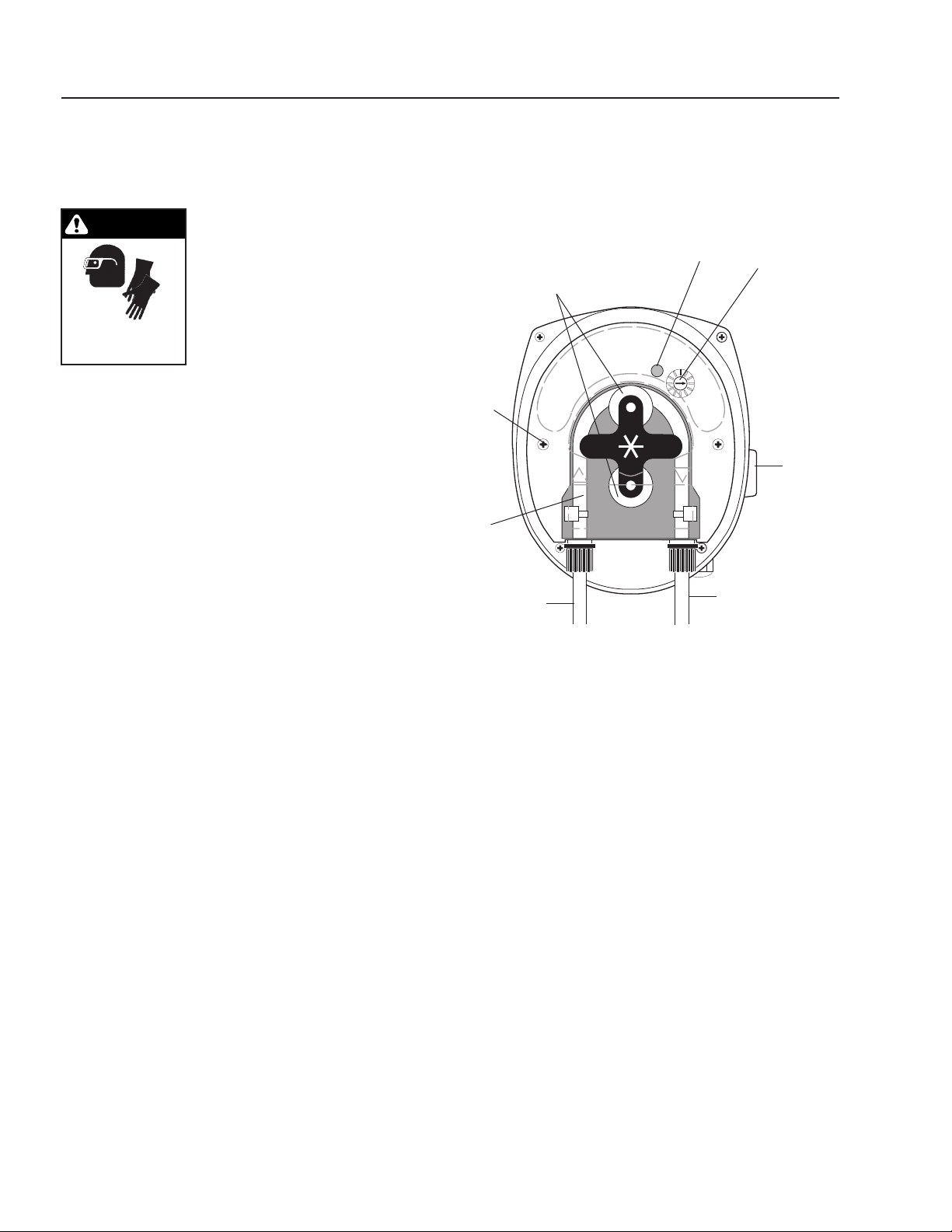
40
HBG EVAPORATOR OPERATOR’S MANUAL
HBG • 8.913-990.0-K
REPLACING PUMP
HEAD TUBING:
WARNING: Wear protective
gloves, goggles, and other ad-
equate protection for the chemi-
cal hazard. Before replacing the
pump head, remove chemical
from tubing as follows. Remove
strainer from chemical tank then
run pump until all chemical is
removed from the tubing.
1. Remove the compression fi ttings from the tubing at
the pump head.
2. Pull the suction and discharge tubing from the pump
head.
3. Remove the front cover.
4. Rotate the pump rollers to a vertical position.
5. Lift the inlet fi tting out of the housing.
6. Pull the tube out while rotating the pump rollers
clockwise.
7. Remove the outlet fi tting.
8. Install the inlet fi tting for the new tube assembly.
9. Press the tube into place in front of a roller while
rotating the roller assembly clockwise.
10. Install the outlet fi tting.
11. Reconnect the suction and discharge lines.
12. Install the front cover.
CAUTION: DO NOT LOSE THE BEARING FROM THE
CENTER HOLE IN THE COVER PLATE.
WARNING
WEAR PROTECTIVE
GLOVES, GOGGLES
AND CLOTHING.
Figure 1
Indicator
Light
On-Off-Full
Speed
Switch
(right or
left side)
Cover
Screws
Squeeze
Tube
Speed
Adjusting
Screw w/
Indexing
Marks
Pump
Rollers
Discharge
Inlet
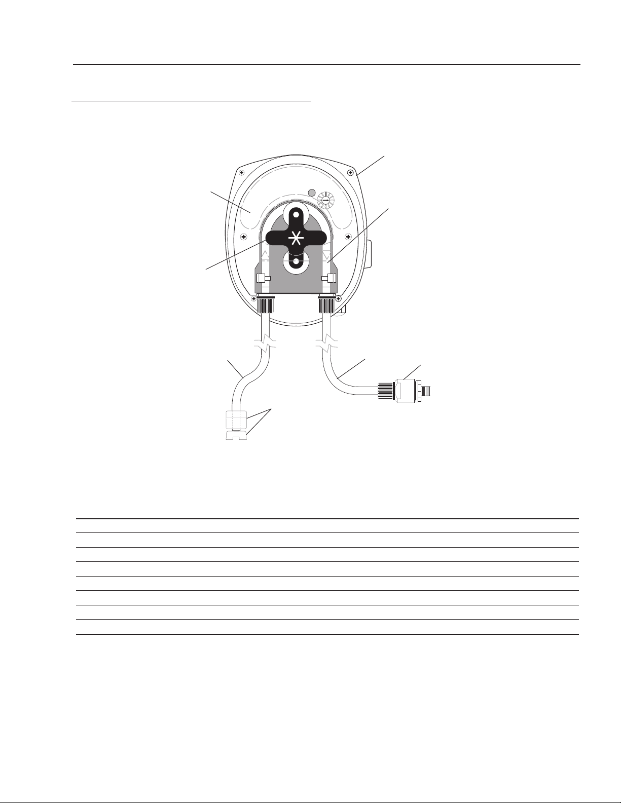
HBG EVAPORATOR OPERATOR’S MANUAL
41
HBG • 8.913-990.0-K
METERING PUMP AND PARTS LIST
ITEM PART NO. DESCRIPTION QTY
1 8.919-139.0 Pump, Peristaltic, PR-7, 8-45 gpd, Sekokem 1
2 8.750-963.0 Tube, Squeeze, Sekokem, PR-7,
* 8-45 gpd 1
3 8.749-860.0 Check Valve, PVC 1
4 8.749-857.0 Tubing, 1/4", PE, Black AR
5 8.749-863.0 Strainer, w/welght 1
6 8.711-737.0 Tubing, 1/8", ID, Norprene AR
7 8.751-801.0 Faceplate, PRS-1/PR-7 1
8 8.751-375.0 Roller Assembly, PR-7 1
* Alternative tubing materials are available
1
2
6
3
4
7
8
5
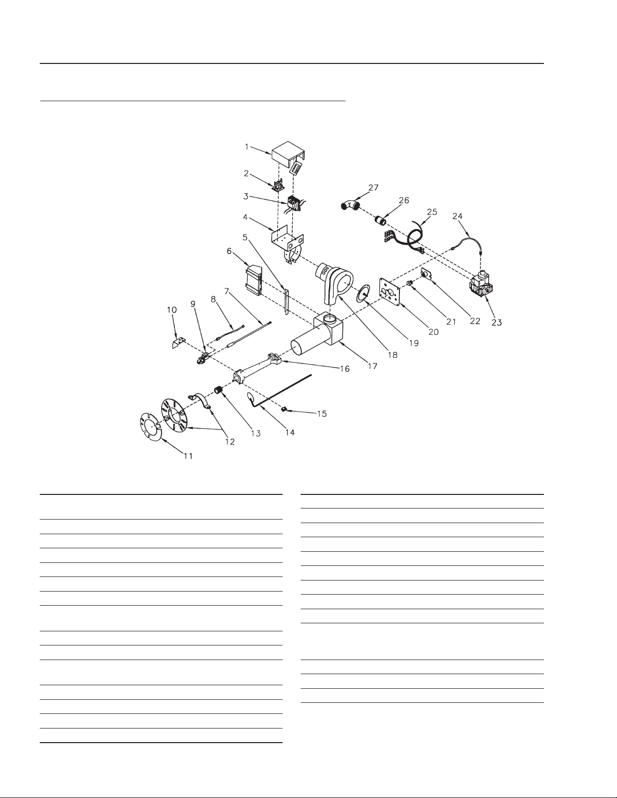
42
HBG EVAPORATOR OPERATOR’S MANUAL
HBG • 8.913-990.0-K
Burner Assembly, HBG-15 Model # P250AFEP
PART # 8.717-099.0 NATUAL GAS
PART # 8.717-101.0 LIQUID PROPANE
ITEM PART NO. DESCRIPTION
1 61823-003 Control Box Cover Assembly
62998-001 Control Box Cover Assembly (LP)
2 61444-002 Relay, Time Delay Assembly
3 8.717-985.0 Transformer, 34v/30va
4 62301-001 Control Box/Strap Assembly
5 62700-001 Bracket
6 8.717-990.0 Ignition Module (S8600H-1006)
7 8.718-009.0 Ignition Wire Assembly
8 8.717-986.0 Tube 1/4" x 5.25"
62320-001 Tube 1/4" x 7.5" (LP)
9 8.718-012.0 Burner Pilot
10 8.717-897.0 Pilot Shield
11 100428 Gasket
8.717-736.0 Gasket (LP)
12 21756-011 Flange, Adjustable
13 600748 Flame Retention Assembly
14 8.717-989.0 Flame Spreader Assembly
15 61840 Flame Spreader Bracket
ITEM PART NO. DESCRIPTION
16 61817 Venturi-P250AF
17 8.718-004.0 Air Tube Housing
18 8.717-984.0 Motor Blower Assembly
19 8.718-003.0 Air Shutter Assembly
20 62049-0902 Housing Coverplate Assembly
21 8.724-854.0 Orifi ce (.242")
8.718-197.0 Orifi ce (.157") (LP)
22 62898-001 Orifi ce Holder
23 8.717-991.0 Gas Valve, Honeywell
24 62320-012 Tube 1/4" x 10.00"
15407 ▲ Compression Nut
15408 ▲ Compression Sleeve
25 62245-001 Wiring Harness
26 60017 Nipple 3/4" x 2-1/2"
27 60016 Elbow 1/2" NPT x 3/4" NPT
▲ Not Shown
8.906-076.0 Factory Conversion, NG to LP
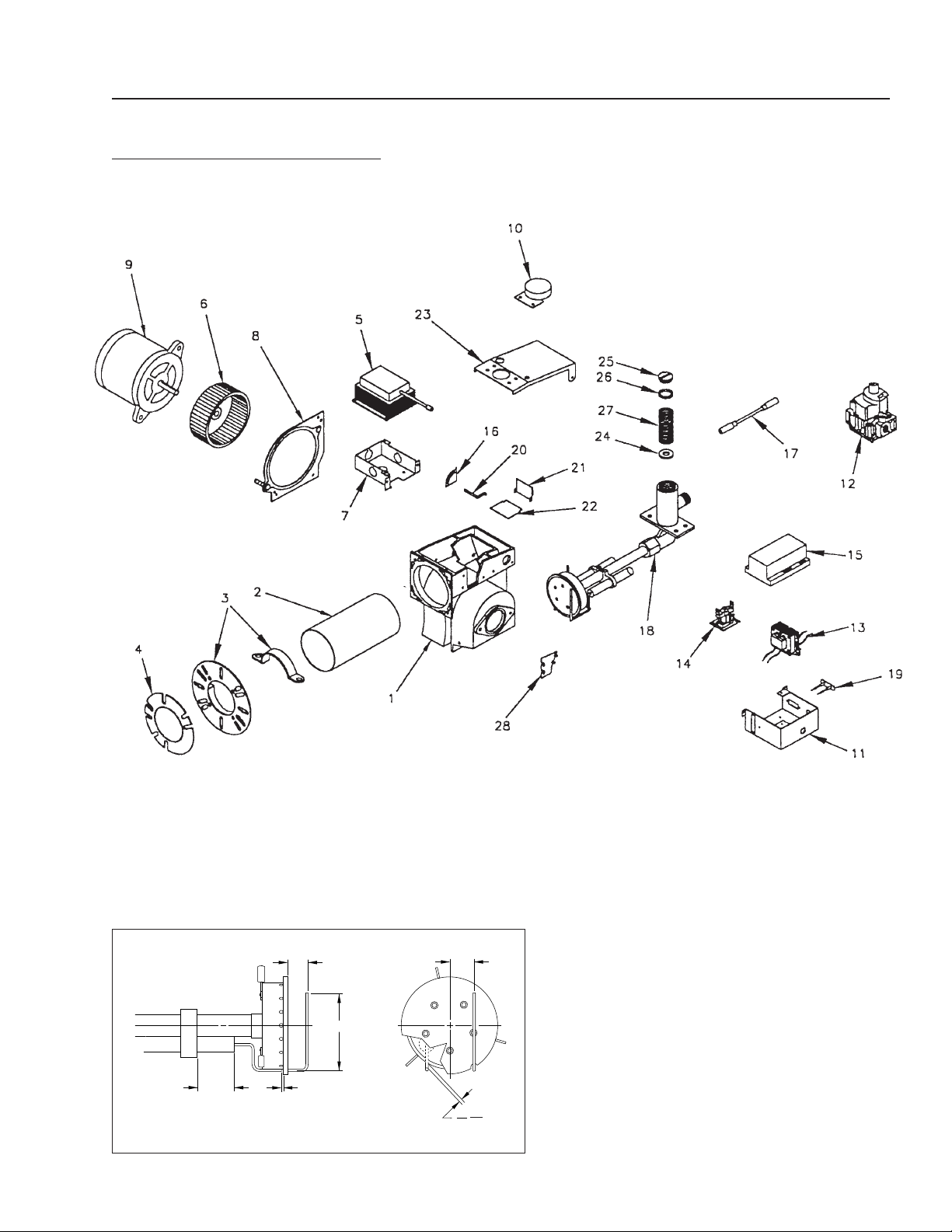
HBG EVAPORATOR OPERATOR’S MANUAL
43
HBG • 8.913-990.0-K
Burner Assembly, HBG-30
MODEL #HSG-400 PART # 8.717-100.0
.09
2.50
.06
.08
.75
.80
Sensor and Electrode Alignment
REF
1.25
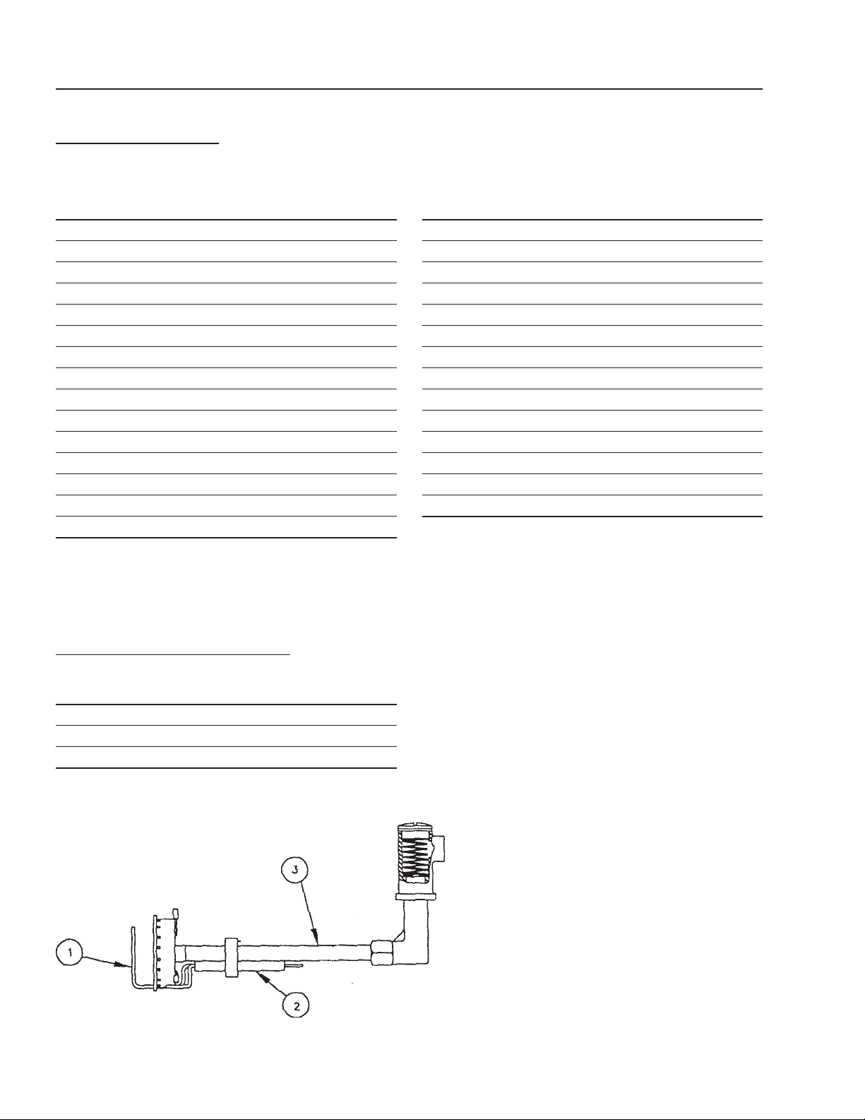
44
HBG EVAPORATOR OPERATOR’S MANUAL
HBG • 8.913-990.0-K
ITEM PART NO. DESCRIPTION
1 100935-001 Burner Housing
2 8.718-015.0 Air Tube , 6"
3 8.717-843.0 Adjustable Flange Assembly
4 8.717-736.0 Gasket
5 8.718-001.0 Transformer
6 8.717-842.0 Blower Wheel
7 21319 J-Box
8 21658 Side Plate
9 20627 Motor, 1/5-3450/115/60
10 8.718-013.0 Pressure Switch
11 62408-001 Control Box
12 8.717-992.0 Gas Valve
13 8.717-985.0 Transformer
14 8.718-000.0 Relay
15 8.718-006.0 Primary Control
Burner Assembly
PARTS LIST MODEL #HSG-400
ITEM PART NO. DESCRIPTION
16 100377-002 Off Cycle Indicator
17 8.718-008.0 Ignition Wire
18 62473-009 Gas Train Asm
19 60178 Terminal Strip
20 100372 Damper Arm
21 100378 Off Cycle Bracket
22 100371 Off Cycle Damper
23 62404-002 Housing Cover
24 8.718-198.0 Orifi ce, 15/32" NG1
8.718-199.0 Orifi ce Q (.332) LP1
25 62385-001 Cap
26 62401-001 Gasket
27 62410-001 Spring
28 62399-002 Shield
ITEM PART NO. DESCRIPTION
1 8.717-996.0 Probe
2 8.717-997.0 Electrode
3 62575-001 Chamber/Manifold Asm
HSG Gas Train Assembly

HBG EVAPORATOR OPERATOR’S MANUAL
45
HBG • 8.913-990.0-K
TROUBLESHOOTING
PROBLEM POSSIBLE CAUSE SOLUTION
MACHINE WON’T
POWER UP
Breaker tripped Reset breaker and reset batch cycle
controller by pushing the F1/RST button.
Batch cycle complete Reset batch cycle controller by pushing the
F1/RST button.
PILOT DOES
NOT LIGHT
(HBG-15)
Air in gas line Bleed gas line.
High or low gas pressure Adjust air regulator.
Blocked pilot orifi ce Replace or clean orifi ce.
PILOT GOES OUT
FREQUENTLY DURING
STANDBY (HBG-15)
Restriction in pilot gas line Clean line.
Low gas pressure Adjust pressure regulator.
Blocked pilot orifi ce Replace or clean orifi ce.
PILOT GOES OUT
WHEN GAS VALVE
OPENS (HBG-15)
Restriction in pilot gas line Clean pilot orifi ce.
High or low gas pressure Test and adjust pressure.
Excessive pressure drop when main
gas valve opens
Increase size of inlet gas piping.
BURNER MOTOR
DOES NOT RUN
Burned out fuse or current is off Check fuse and replace.
Thermostat or limit defective or im-
properly set
Test and reset thermostat.
Relay or transformer defective Test and replace.
Motor burned out Replace.
Improper wiring Check all connections.
Manual reset high temperature switch
is tripped
Scrape and clean fl oor of tank. Reset
swtich on back of control box.
Liquid level is too high. High fl oat is in
up position
Remove enough water from tank to lower
level fl oat then restart burner.
BURNER MOTOR
RUNNING BUT
NO FLAME
Pilot out (HBG-15) Restart burner.
Very low or no gas pressure Adjust pressure regulator.
Motor running too slow Check voltage.
SHORT NOISY
BURNER FLAME
Pressure regulator set too low Increase pressure.
Air shutter open too wide Close shutter.
Too much pressure drop in gas line Increase gas pipe size.
Defective regulator Replace.
LONG YELLOW
FLAME
Air shutter not open enough Open air shutter (see Air Setting).
Air openings or blower wheel clogged Clean.
Too much input gas Turn gas pressure down.
MAIN GAS VALVE DOES
NOT CLOSE WHEN
BLOWER STOPS
Defective valve Replace gas valve.
Obstruction on valve seat Replace gas valve.
REGULATOR VENT
LEAKING GAS
Hole in diaphragm Replace regulator
BURNER IGNITES FOR
2-4 SECONDS (HBG-30)
Check main voltage polarity Switch black & white incoming power wires.

46
HBG EVAPORATOR OPERATOR’S MANUAL
HBG • 8.913-990.0-K
TROUBLESHOOTING
PROBLEM POSSIBLE CAUSE SOLUTION
BURNER WON’T SHUT
DOWN AT LOW WATER
Low water fl oat does not work Check switch for continuity, then
adjust or replace.
WATER WON’T HEAT UP
OR HEATS UP TOO SLOWLY
Sludge buildup on fl oor or tank Scrape sludge from bottom of tank.
Incorrect gas supply for burner Recheck manifold. Reset if needed.
AIR PUMP
WON’T START
Long fl oat, top micro switch not
energized. Water too high
Keep evaporating or
manually lower the water level.
Air regulator setting adjusted too low Readjust air regulator to between 50
and 100 psi.
Air pump solenoid plugged Clean out.
No voltage to air pump solenoid coil Check wiring in electrical box.
Replace parts as needed.
Bad air pump solenoid coil Replace solenoid coil.
WASTEWATER
DISCHARGING FROM
AIR PUMP EXHAUST
Check for diaphragm rupture If ruptured, replace.
Check for diaphragm nut Tighten nut.
AIR BUBBLES IN
DISCHARGE HOSE
Check connections of suction plumbing If loose, retighten.
Check band clamps on intake manifold If loose, retighten.
Check o-rings between intake manifold
and fl uid caps
Replace
o-rings if worn.
Check tightness of diaphragm nut Tighten nut.
AIR PUMP BLOWS AIR
OUT MAIN EXHAUST
WHENSTALLED ON
EITHER STROKE
Check U cups on spool in major valve Replace if needed.
Check valve plate and insert for wear Replace if needed.
Check sleeve and o-ring on diaphragm
connecting rod
Replace if needed.
Check o-rings on piston for wear Replace if needed.
LOW DISCHARGE G.P.M.
Check air supply Adjust to between 50 and 100 psi.
Check for plugged discharge hose Unplug discharge hose.
For the pump to prime itself it must be
mounted in a vertical position so that
the balls will check by gravity
Level machine.
“Check for pump cavitation - suc-
tion pipe should be 1/2”” minimum or
larger if high viscosity fl uids are being
pumped. Suction hose must be non-
collapsible type, capable of pulling a
high vacuum”
Replace hoses if undersized.
Check all joints on intake manifolds
and suction connections. These must
be air tight
Tighten all joints and connections.
Check for sticking or improperly seating
check valves
Clean check valves.
If pump cycles at a high rate or runs er-
ratically, check piston o-rings for wear
Replace
o-rings if needed

HBG EVAPORATOR OPERATOR’S MANUAL
47
HBG • 8.913-990.0-K
ETL Certifi ed
SPECIFICATIONS
HBG COST FORMULAS
Propane conversion from gallons of propane to therms for use in chart below: 1 Therm = 1.0929 gallons of propane.
Multiply the cost of 1 gallon of propane by 1.0929 to determine the propane cost per therm.
Example: Propane = $1.50 gallon. Multiply 1.0929 (gallons of propane per therm) x $1.50 (cost of gallon of
propane)= $1.6393 per therm.
Constants:
1 cubic foot of natural gas = 1,000 BTU's 1 gallon of propane = 91,500 BTU's
1 gallon of propane = 0.915 therms 1 therm = 100 standard cubic feet of natural gas
1 therm = 100,000 BTU's
Operating Cost for Natural Gas:
Gas Cost (Cost per Gallon) = HBG Rating BTU's per Hour x Local Cost of Fuel per Therm
BTU's per Therm x HBG Evaporation Rate
Operating Cost for Electricity:
Electricity Cost (Cost per Gal) = Volts x Amps x Cost of Kilowatt Hour
1000 x HBG Evaporation Rate
Example for HBG-15: 180,000 BTU/Hr, 40¢/Therm, 120 Volts, 3 Amps, 6¢/KWH
Gas Cost (¢/Gal) = 180,000 x 40 = 5.5 ¢/Gal
100,000 x 13
Electricity Cost (¢/Gal) = 120 x 3 x 6 = .1¢/Gal
1000 x 13
Total Cost = 6.2¢ (gas) + .1¢ (elec) = 6.3¢/Gal
MODEL FUEL USAGE EVAPORATION RATE
HBG-15 180,000 BTU / HR 13 gallons per hour
HBG-30 311,000 BTU / HR 28 gallons per hour
MODEL HBG-15 HBG-30
EVAPORATION RATE
10-15 GPH (38 - 57 Liter/Hr) 25-30 GPH (95 - 114 Liter/Hr)
ENERGY SOURCE
Natural Gas or LPG
ENERGY USAGE
180,000 BTU/HR 311,000 BTU/HR
TANK CAPACITY
70 Gallons (265 Liters) 120 Gallons (379 Liters)
TANK MATERIAL MILD STEEL
“3/8”” Plate Floor, 3/16”” Gauge Walls”
STAINLESS STEEL
“1/4”” Plate Floor, 12 Gauge Walls”
INSULATION
Air Insulated
WEIGHT
1,215 Lbs. (552 Kg) 1,485 Lbs. (675 Kg)
DIMENSIONS W x L x H
33" x 78.5" x 65"
(84 x 199 x 165 Cm)
90" x 44" x 70"
(229 x 112 x 178 Cm)
POWER REQUIREMENTS
120V, 1 PH, 3 Amps (13 amps for electric autofi ll)
WARRANTY
1 Year Parts 1 Year Parts
Note: NG calculations

48
HBG EVAPORATOR OPERATOR’S MANUAL
HBG • 8.913-990.0-K
PREVENTATIVE MAINTENANCE
This evaporator was produced with the best available materials and quality craftsmanship. However, you as the owner
have certain responsibilities for the correct care of the equipment. Attention to regular preventative main te nance
pro ce dures will assist in preserving the performance of your equipment. Contact your Landa dealer for main te nance.
Regular pre ven ta tive maintenance will add many hours to the life of your machine. Perform main te nance more often
under severe conditions.
MAINTENANCE SCHEDULE
Sludge Inspect
Daily
Remove
After each complete batch
Liquid Level Switches Inspect
Daily
Clean
Weekly
Inspect and Clean Tank(s)
After each complete batch
Lubricate Draft Inducer Motor
Semi-annually
Clean Draft Inducer Fins
Monthly
Wastewater pH between 8-10
Daily
Clean Water Screen/Filter
Weekly

HBG SERIES PRESSURE WASHER OPERATOR’S MAN U AL
49
HBG • 8.913-990.0-K
LIMITED NEW PRODUCT WARRANTY
WASH WATER / WATER TREATMENT SYSTEMS
WHAT THIS WARRANTY COVERS
All
WATER MAZE
water treatment systems are warranted by to the original purchaser to be free from defects in materials
and workmanship under normal use, for the periods specified below. This Limited Warranty, subject to the exclusions shown
below, is calculated from the date of the original purchase, and applies to the original components only. Any parts replaced
under this warranty will assume the remainder of the part’s warranty period. A 60 day grace period will be given for installa-
tion.
ONE YEAR PARTS AND 30 DAY LABOR WARRANTY:
All components excluding normal wear items as described below.
WARRANTY PROVIDED BY OTHER MANUFACTURERS:
Motors, which are warranted by their respective manufacturers, are serviced through these manufacturers’ local authorized
service centers.
WATER MAZE
cannot provide warranty on these items.
WHAT THIS WARRANTY DOES NOT COVER
This warranty does not cover the following items:
1. Normal wear items, such as seals, filters, gaskets, O-rings, packings, pistons, brushes, filtering media, ozone
bulbs, sensors, UV scanners, oil-skimmer belt, impedance sensor. Minor leaks covered first time on original start-
up only.
2. Damage or malfunctions resulting from accidents, abuse, modifications, alterations, incorrect installation, improper
servicing, failure to follow
manufacturer’s maintenance instructions, or use of the equipment beyond its stated
usage specifications as contained in the operator’s manual.
3. Damage due to freezing, sludge build-up, chemical deterioration (oxidation, chloride or fluoride corrosion), and
rust.
4. Damage to components from fluctuations in electrical or water supply.
5. Normal maintenance service, including adjustments.
6. Transportation to service center, field labor charges, or freight damage.
7. Consumables and water quality.
WHAT YOU MUST DO TO OBTAIN WARRANTY SERVICE
While not required for warranty service, we request that you register your
WATER MAZE
Product by returning the com-
pleted registration card. In order to obtain warranty service on items warranted by
WATER MAZE
, you must return the
product to your Authorized
WATER MAZE
Dealer, freight prepaid, with proof of purchase, within the applicable warranty
period. If the product is permanently installed, you must notify your Authorized
WATER MAZE
Dealer of the defect. Your
Authorized
WATER MAZE
Dealer will file a claim with
WATER MAZE
, who must subsequently verify the defect. In most
cases, the part must be returned to
WATER MAZE
freight prepaid with the claim. For warranty service on components
warranted by other manufacturer’s, your Authorized
WATER MAZE
Dealer can help you obtain warranty service through
these manufacturers’ local authorized service centers.
LIMITATION OF LIABILITY
WATER MAZE’S
liability for special, incidental, or consequential damages is expressly disclaimed. In no event shall
WATER MAZE’S
liability exceed the purchase price of the product in question.
WATER MAZE
makes every effort to ensure
that all illustrations and specifications are correct, however, these do not imply a warranty that the product is merchantable
or fit for a particular purpose, or that the product will actually conform to the illustrations and specifications. Our obligation
under this warranty is expressly limited at our option to the replacement or repair at a service facility or factory designated
by us, of such part or parts as inspection shall disclose to have been defective. THE WARRANTY CONTAINED HEREIN
IS IN LIEU OF ALL OTHER WARRANTIES, EXPRESS OR IMPLIED, INCLUDING ANY IMPLIED WARRANTY WATER
QUALITY, MERCHANTABLIITY OR FITNESS FOR A PARTICULAR PURPOSE ARE EXPRESSLY LIMITED TO THE
DURATION OF THIS WARRANTY.
This warranty gives you specific legal rights and you may also have other rights which
vary from state to state.
WATER MAZE
does not authorize any other party, including authorized
WATER MAZE
Distributors,
to make any representation or promise on behalf of
WATER MAZE
, or to modify the terms, conditions, or limitations in any
way. It is the buyer’s responsibility to ensure that the installation and use of
WATER MAZE
products conforms to local
codes. While
WATER MAZE
attempts to assure that its products meet national codes, it cannot be responsible for how the
customer chooses to use or install the product. Some states do not allow limitations or exclusion or limitation of incidental or
consequential damages, so the above limitation or exclusion may not apply to you.

HBG • #8.913-990.0 • Printed in U.S.A.