Loading ...
Loading ...
Loading ...
20
WATERMAZE SERIES OPERATOR’S MANUAL
WB • 8.913-984.0-N
The Veri-Flame is the controller which proves all of the
interlocks. It provides for a purge cycle to insure that
there are no combustibles in the sparger tube before
the trial for ignition (TFI). The length of the purge cycle
is determined by the settings on the Veri-Flame. It is
preset at the factory for 15 seconds.
If you need to check the settings on your Veri-Flame
or if you replace a Veri Flame and it needs to be set,
remove the screws holding the cover on and unplug the
cover from the back. Dipp switches are located on the
reverse side. Set the eight switches as follows: switch 1
ON, switch 2 OFF, switch 3 ON, switch 4 ON, switches
5, 6, 7 and 8 OFF.
If switch 1 is ON, the burner will recycle once after an
air or main flame failure. Otherwise, the system will shut
down.
A pilot light is not used so switch 2 is set to OFF. Switch
3 controls the amount of time the machine has for TFI.
With this switch set to ON, the machine has 10 seconds
for TFI. Switches 4 through 8 control the amount of
purge time before TFI. Switch 4 gives the machine a 15
second purge before TFI.
A Veri-Flame and U.V. scanner tester is available
(#7-8063).
3 POINT SENSOR CONTROL
The 3 point sensor control is part of the safety interlock
system and also controls the wastewater air diaphragm
pump.
The bottom rod is the low water safety position. If the
wastewater level is too low, this rod, working through the
Veri-Flame, will not allow the burner to ignite. When the
wastewater level drops to the position of the middle rod,
there is a demand for water and the wastewater pump
turns on. The air diaphragm pump continues to run until
the top rod is reached by the wastewater. At this point
the pump shuts off. When the level drops to the middle
rod, the wastewater pump restarts again.
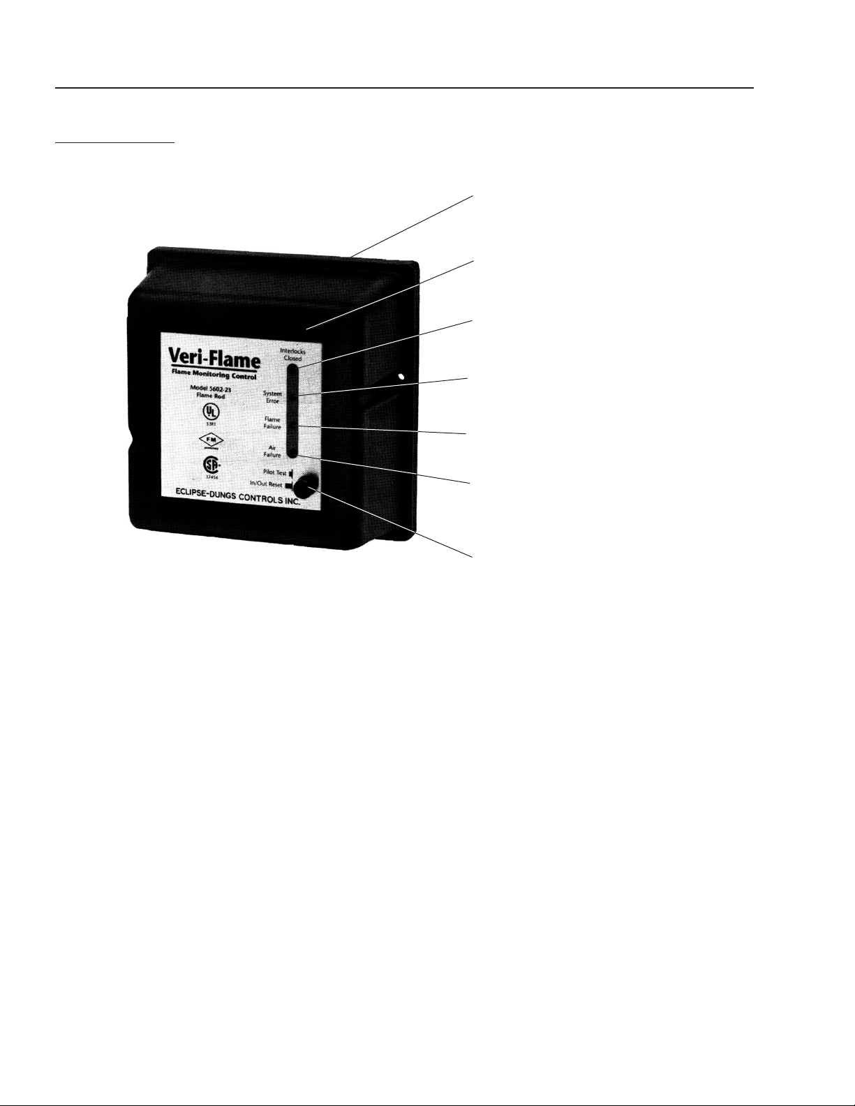
VERI-FLAME
#7-8061
"Flame Signal" – should be red
Button in "Out" position
"Air Failure" – Blower
"Flame Failure" – UV Scanner
"System Error" – These are your
interlocks, this light shouldn't be
illuminated, if it is check interlocks.
"Interlocks Closed" – should be green
Dipp Switches
Figure 8
Loading ...
Loading ...
Loading ...