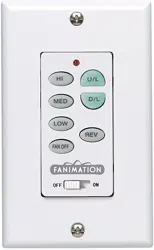
C23 Wall Control
SPECIFICATION and INSTRUCTION SHEET
How to Wire and Operate Your C23 Wall Control
NOTE: If fan or supply wires are different colors than indicated,
have this unit installed by a qualified electrician.
Check to see that all connections are tight, including
ground, and that no bare wire is visible at the wire
connectors, except for the ground wire. Do not operate
fan until the blades is in place. Noise and fan damage
could result.
WARNING
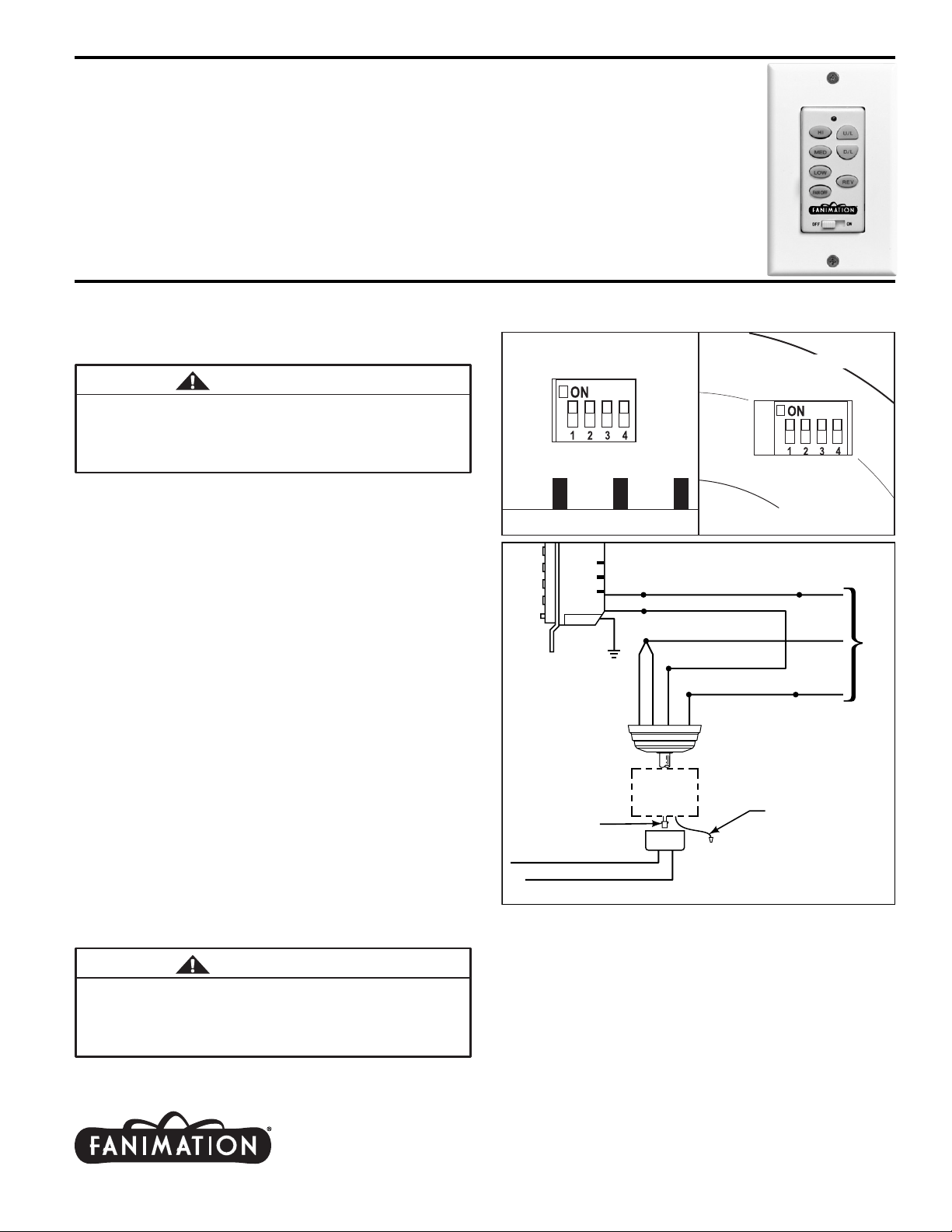
Figure 1bFigure 1a
Wall Transmitter Unit Detail
(located on side of Wall Control)
Receiver Unit Detail
Figure 2
FAN
MOTOR
UNIT
BL-AC IN L
WH-AC IN N
BLUE-FOR LIGHT DOWN
BLK-TO MOTOR L
WH-TO MOTOR N
GRN or BARE GROUND
GRN from hanger ball
GRN from bracket
120 VAC SUPPLY
(User Supplied)
2. Installing Receiver in Switch Cup:
• Slide remote Receiver into the Switch Cup, connect the
plug from the fan motor assembly into the socket located in
the receiver unit. Install Switch Cover Housing.
• Connect wires as indicated: (Figure 2)
– Orange wire for Optional LK25 Side Light Kit. See LK25
Instructions for details (Treventi models only).
– Green Hanger Bracket and Hanger Ball wires to BARE
(ground) wire.
– BLACK Fan Motor wire to BLACK supply wire.
– WHITE Fan Motor wire to WHITE supply wire.
• Position all connected wires to allow installation of ceiling
canopy.
• Install canopy using threaded rods, lockwashers, and
knurled knobs.
• Restore electrical power.
1. Setting the Code: The remote unit has 16 different code
combinations. It may be necessary to test a couple frequency
code settings to improve signal reception and/or eliminate
interference from other remote control household items.
Multiple fans should have different code settings to allow
independent fan control. To set the code, perform these
steps.
• Transmitter: located on back side of unit. Slide code
switches to your choice of up or down position. Factory setting
is all up. Do not use this position. With a small screwdriver or
ball point pen slide firmly up or down (Figure 1a).
• Receiver: Slide code switches to the same positions as
set on your transmitter (Figure 1b).
3. Operating & Using Wall Control Transmitter:
• HI Push Button – high fan speed
• MED Push Button – medium fan speed
• LOW Push Button – low fan speed
• REV Push Button – toggles between air upflow and air downflow
• OFF Push Button – fan off
• U/L Push Button – use top portion of light button to operate up light
• D/L Push Button – use bottom portion of light button to operate optional
down light
To avoid possible electrical shock, be sure electricity is
turned off at the main fuse box before wiring.
NOTE: If you are not sure if the outlet box is grounded,
contact a licensed electrician for advice, as it must be
grounded for safe operation.
WARNING
WH-FOR LIGHT DOWN
NOTE: To control either light hold down key to increase or decrease
brightness. Tap key quickly to turn light on or off. The light keys have
auto resume and will stay at the same brightness as the last time it was
turned off.
GRN
Receiver
Unit
GRN
BLK
BLK
DESCRIPTION: One Ceiling Fan, Uplight & Downlight, 3 Speed, Reversing Wall Control
ELECTRICAL SPECS: 120 Volts, 60 Hertz, Fan 1.0 amp, Light Rating 300W
Incandescent or Halogen, 3 Wire Installation
FAN MODEL USED: The Treventi Series and The Sandella (with the Up/Down lights or
optional side lights)
Orange wire from Motor into
optional LK25 Side Light Kit
(Treventi models only)
Plug from Motor
into Receiver Connector
Copyright 2004 Fanimation
2004/08
10983 Bennett Parkway
Zionsville, IN 46077
(888) 567-2055 • FAX (866) 482-5215
Outside U.S. call (317) 733-4113
Visit Our Website @ www.fanimation.com
