Loading ...
Loading ...
Loading ...
8
5. Installing the refrigerant piping
Warning:
When pumping down the refrigerant, stop the compressor before disconnect-
ing the refrigerant pipes. The compressor may burst and cause injury if any
foreign substance, such as air, enters the system.
5.5. Connecting pipes (Fig. 5-4) (Fig. 5-5)
• Conduct sufcient anti-condensation and insulation work to prevent water drip-
ping from the refrigerant piping. (liquid pipe/gas pipe)
• Increase insulation depending on the environment where the refrigerant piping is
installed, or condensation may occur on the surface of the insulation material.
(Insulation material Heat-resistant temperature: 120 °C, 248 °F, Thickness:
15 mm, 5/8 inch or more)
* When the refrigerant piping is used in locations subject to high tempera-
ture and humidity such as in the attic, further addition of insulation may be
required.
• To insulate the refrigerant piping, apply heat-resistant polyethylene foam between
the indoor unit and insulation material as well as to the net between the insulation
material lling all gaps.
(Condensation forming on the piping may result in condensation in the room or
burns when contacting the piping.)
• The indoor parts of the drain pipe should be wrapped with polyethylene foam insu-
lation materials (specic gravity of 0.03, thickness of 9 mm (3/8 inch) or more).
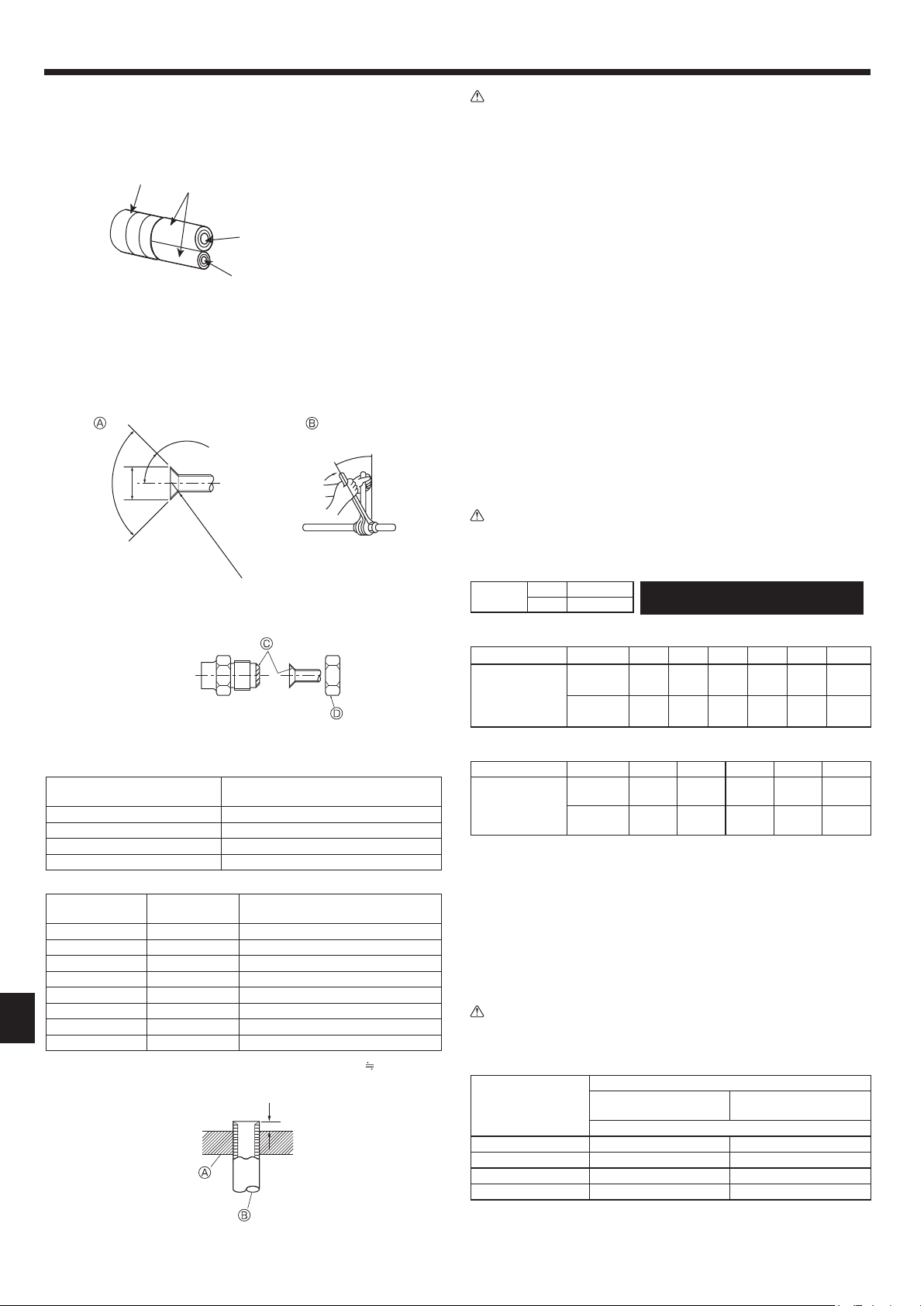
[Fig. 5-5]
• Apply thin layer of refrigerant oil to pipe and joint seating surface before tightening
are nut. A
• Use 2 wrenches to tighten piping connections. B
• Use leak detector or soapy water to check for gas leaks after connections are
completed.
• Apply refrigerating machine oil over the entire are seat surface. C
• Use the are nuts as follows. D
Warning:
When installing the unit, securely connect the refrigerant pipes before starting
the compressor.
■ Pipe size (Outdoor unit-Branch box)
Pipe size
(ømm) (inch)
Liquid ø9.52 (3/8)
Gas
ø15.88 (5/8)
■ Pipe size (Branch box-Indoor unit) *Case of M series or S series Indoor unit
Indoor unit type (BTU/h) 06 09 12 15 18 24
Pipe size
(ømm) (inch)
Liquid
ø6.35
(1/4)
ø6.35
(1/4)
ø6.35
(1/4)
ø6.35
(1/4)
ø6.35
(1/4)
ø9.52
(3/8)
Gas
ø9.52
(3/8)
ø9.52
(3/8)
ø9.52
(3/8)
ø12.7
(1/2)
ø12.7
(1/2)
ø15.88
(5/8)
■ Pipe size (Branch box-Indoor unit) *Case of P series indoor unit
Indoor unit type (BTU/h) 12 18 24 30 36
Pipe size
(ømm) (inch)
Liquid
ø6.35
(1/4)
ø6.35
(1/4)
ø9.52
(3/8)
ø9.52
(3/8)
ø9.52
(3/8)
Gas
ø12.7
(1/2)
ø12.7
(1/2)
ø15.88
(5/8)
ø15.88
(5/8)
ø15.88
(5/8)
• When bending the pipes, be careful not to break them. Bend radius of 100 mm
(4 inch) to 150 mm (6 inch) are sufcient.
• Make sure the pipes do not contact the compressor. Abnormal noise or vibration
may result.
1 Pipes must be connected starting from the indoor unit.
Flare nuts must be tightened with a torque wrench.
2 Flare the liquid pipes and gas pipes and apply a thin layer of refrigeration oil (Ap-
plied on site).
• When usual pipe sealing is used, refer to Table 2 for aring of R410A refrigerant
pipes.
The size adjustment gauge can be used to conrm A measurements.
Caution:
• Be sure to wrap insulation around the piping. Direct contact with the bare
piping may result in burns or frostbite.
Table 2 (Fig. 5-6) mm (inch)
Copper pipe O.D.
A
Flare tool for R410A Flare tool for R22·R407C
Clutch type
ø6.35 (1/4) 0 - 0.5 (0 - 1/64) 1.0 - 1.5 (3/64 - 1/16)
ø9.52 (3/8) 0 - 0.5 (0 - 1/64) 1.0 - 1.5 (3/64 - 1/16)
ø12.7 (1/2) 0 - 0.5 (0 - 1/64) 1.0 - 1.5 (3/64 - 1/16)
ø15.88 (5/8) 0 - 0.5 (0 - 1/64) 1.0 - 1.5 (3/64 - 1/16)
The lineup of a connectable indoor unit
depends on a district/areas/country.
A (Fig. 5-5)
Copper pipe O.D.
(mm) (inch)
Flare dimensions
øA dimensions (mm) (inch)
ø6.35 (1/4) 8.7 - 9.1 (5/16 - 3/8)
ø9.52 (3/8) 12.8 - 13.2 (1/2)
ø12.7 (1/2) 16.2 - 16.6 (5/8)
ø15.88 (5/8) 19.3 - 19.7 (3/4)
Copper pipe O.D.
(mm) (inch)
Flare nut O.D.
(mm) (inch)
Tightening torque
(N·m)* (ft·lb)
ø6.35 (1/4) 17 (11/16) 14 - 18 (10 - 13)
ø6.35 (1/4) 22 (7/8) 34 - 42 (25 - 30)
ø9.52 (3/8) 22 (7/8) 34 - 42 (25 - 30)
ø9.52 (3/8) 26 (1-1/4) 49 - 61 (35-44)
ø12.7 (1/2) 26 (1-1/4) 49 - 61 (35-44)
ø12.7 (1/2) 29 (1-1/8) 68 - 82 (49 - 59)
ø15.88 (5/8) 29 (1-1/8) 68 - 82 (49 - 59)
ø15.88 (5/8) 36 (1-7/16) 100 - 120 (71 - 87)
* 1 N·m
10 kgf·cm
A
B
C
D
A Liquid pipe
B Gas pipe
C Insulation
D Taping
Fig. 5-4
Fig. 5-5
Fig. 5-6
A Flare cutting dimensions
B Flare nut tightening torque
90° ± 0.5°
A Die
B Copper pipe
A
øA
R1/64” to R1/32”
45°± 2°
RG79D595H06_EN.indd 8 9/7/2016 9:49:56 AM
Loading ...
Loading ...
Loading ...