Loading ...
Loading ...
Loading ...
6
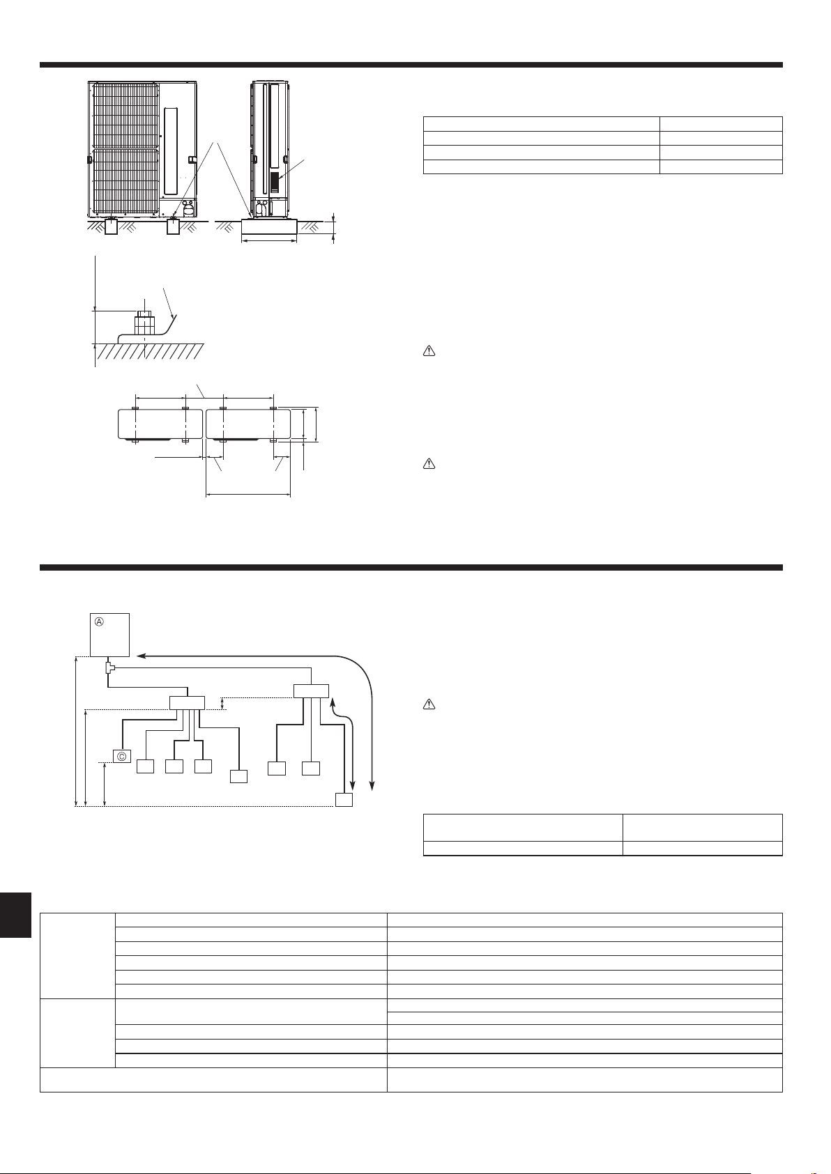
4. Installing the outdoor unit
• Be sure to install the unit in a sturdy, level surface to prevent rattling noises dur-
ing operation. (Fig. 4-1)
<Foundation specications>
Foundation bolt M10 (3/8")
Thickness of concrete 120 mm (4-23/32”)
Length of bolt 70 mm (2-3/4”)
Weight-bearing capacity 320 kg (705 lbs)
• Make sure that the length of the foundation bolt is within 30 mm (1-3/16”) of the
bottom surface of the base.
• Secure the base of the unit rmly with four-M10 foundation bolts in sturdy loca-
tions.
Installing the outdoor unit
• Do not block the vent. If the vent is blocked, operation will be hindered and break-
down may result.
• In addition to the unit base, use the installation holes on the back of the unit to
attach wires, etc., if necessary to install the unit. Use self-tapping screws (ø5 ×
15 mm, ø13/16” × 19/32” or less) and install on site.
Warning:
• The unit must be securely installed on a structure that can sustain its
weight.
If the unit is mounted on an unstable structure, it may fall down and cause
damage or injuries.
• The unit must be installed according to the instructions in order to mini-
mize the risk of damage from earthquakes, typhoons, or strong winds. An
incorrectly installed unit may fall down and cause damage or injuries.
Caution:
• Install the unit on a rigid structure to prevent excessive operation sound or
vibration.
5. Installing the refrigerant piping
5.1. Precautions for devices that use R410A refrigerant
• Refer to page 3 for precautions not included below on using air conditioners with
R410A refrigerant.
• Use ester oil, ether oil, alkylbenzene oil (small amount) as the refrigeration oil ap-
plied to the ared sections.
•
Use C1220 copper phosphorus, for copper and copper alloy seamless pipes, to con-
nect the refrigerant pipes. Use refrigerant pipes with the thicknesses specied in the
table to the below. Make sure the insides of the pipes are clean and do not contain
any harmful contaminants such as sulfuric compounds, oxidants, debris, or dust.
Warning:
When installing or relocating, or servicing the outdoor unit, use only the speci-
ed refrigerant (R410A) to charge the refrigerant lines. Do not mix it with any
other refrigerant and do not allow air to remain in the lines.
If air is mixed with the refrigerant, then it can be the cause of abnormal high pres-
sure in the refrigerant line, and may result in an explosion and other hazards.
The use of any refrigerant other than that specied for the system will cause
mechanical failure or system malfunction or unit breakdown. In the worst
case, this could lead to a serious impediment to securing product safety.
ø6.35 mm (1/4 inch), ø9.52 mm (3/8 inch),
ø12.7 mm (1/2 inch)
Thickness 0.8 mm (1/32 inch)
ø15.88 (5/8 inch) Thickness 1.0 mm (5/128 inch)
• Do not use pipes thinner than those specied above.
Permissible
length
(one-way)
Total piping length c1 + b1 + b2 + a1 + a2 + a3 + a4 + a5 + a6 + a7 + a8 ≤ 150 m (492 ft.)
Farthest piping length (L) *1 c1 + b2 + a8 ≤ 80 m (262 ft.)
Piping length between outdoor unit and branch boxes c1 + b1 + b2 ≤ 55 m (180 ft.)
Farthest branch box from the rst joint (b2) b2 ≤ 30 m (98 ft.)
Farthest piping length after branch box (l) a8 ≤ 25 m (82 ft.)
Total piping length between branch boxes and indoor units a1 + a2 + a3 + a4 + a5 + a6 + a7 + a8 ≤ 95 m (311 ft.)
Permissible
height difference
(one-way)
In indoor/outdoor section (H) *2
H ≤ 50 m (164 ft.) (In case of outdoor unit is set higher than indoor unit)
H ≤ 40 m (131 ft.) (In case of outdoor unit is set lower than indoor unit)
In branch box/indoor unit section (h1) h1 + h2 ≤ 15 m (49 ft.)
In each branch unit (h2) h2 ≤ 15 m (49 ft.)
In each indoor unit (h3) h3 ≤ 12 m (39 ft.)
Number of bends
|
c1 +
b1 + a1 |, |
c1 +
b1 + a2 |, |
c1 +
b1 + a3 |, |
c1 +
b1 + a4 |, |
c1 +
b1 + a5 |, |
c1 +
b2 +
a6 |, |
c1 +
b2 + a7 |, |
c1 +
b2 + a8 | ≤ 15
*1 The piping specication table does not provide a minimum line set length. However, indoor units with connected piping length less than 16 ft. (5 m) could produce intermit-
tent noise during normal system operation in very quiet environments. Please be aware of this important information when installing and locating the indoor unit within the
conditioned space.
*2 Branch box should be placed within the level between the outdoor unit and indoor units.
B
D
B
C C C
C
C C
C
L
I
h2
b2
b1
c1
a6a5
a4a3a2
h3
h1
H
a1
a7 a8
Fig. 5-1
Fig. 4-1
• The thicknesses listed in the table above are based on Japanese stand-
ards. Use pipes with a maximum working pressure of 4.15 MPa [601 PSIG]
or higher according to local standards.
A Outdoor unit
B Branch box
C Indoor unit
D The rst joint
B
(inch)
A M10 (3/8") bolt
B Base
C As long as possible
D Vent
E Set deep in the ground
C
E
D
A
Min. 18-11/16
Min. 1
Max. 1-3/16
23-5/8 23-5/8
8-7/8 8-7/8
13
14-9/16
63/64
41-11/32
RG79D595H06_EN.indd 6 9/7/2016 9:49:56 AM
Loading ...
Loading ...
Loading ...